

Page 1
LX7000 Mar.2002
LX 7000 1.0
Flight Data Computer and GPS Navigation system with
Logger
Pilot’s manual
LX
Navigation d.o.o.
Tkalska 10 SLO 3000 Celje
Tel. +386 3 490 46 70 Fax 71
www.lxnavigation.si
Page 1
Page 2

LX7000 Mar.2002
1 Contents
1 CONTENTS ............................................................................................................................................................ 2
2 GENERAL .............................................................................................................................................................. 4
2.1 S
2.2 T
2.3 R
3 OPERATION MODES .......................................................................................................................................... 8
3.1 SETUP ..............................................................................................................................................................8
3.2 NAVIGATION FUNCTIONS ................................................................................................................................ 21
YSTEM CONFIGURATIONS................................................................................................................................ 4
2.1.1 LX 7000 basic............................................................................................................................................... 4
2.1.2 LX 7000 standard ......................................................................................................................................... 4
2.1.3 LX 7000 IGC ................................................................................................................................................ 4
ECHNICAL DATA.............................................................................................................................................. 5
OTARY SWITCHES AND KEYS (BUTTONS)........................................................................................................ 5
2.3.1 On/Start key..................................................................................................................................................6
2.3.2 Mode selector
2.3.3 Up/down selector
⇔
(rotary switch)................................................................................................................. 6
v
(rotary switch) ............................................................................................................ 6
2.3.4 ENTER key.................................................................................................................................................... 6
2.3.5 ESC/OFF key................................................................................................................................................ 6
2.3.6 ZOOM (rotary switch)................................................................................................................................. 6
2.3.7 Event key....................................................................................................................................................... 7
2.3.8 MC/Bal key ................................................................................................................................................... 7
2.3.9 GO TO key....................................................................................................................................................7
3.1.1 SETUP before password .............................................................................................................................. 8
3.1.1.1 QNH RES (QNH and safety altitude)....................................................................................................................9
3.1.1.2 LOGGER................................................................................................................................................................9
3.1.1.3 INIT ......................................................................................................................................................................11
3.1.1.4 DISPLAY.............................................................................................................................................................11
3.1.1.5 TRANSFER .........................................................................................................................................................12
3.1.1.6 PASSWORD........................................................................................................................................................12
3.1.2 SETUP after password.............................................................................................................................. 12
3.1.2.1 TP (Turn point) ..................................................................................................................................................12
3.1.2.2 OBS. ZONE (observation zone) ........................................................................................................................13
3.1.2.3 GPS.......................................................................................................................................................................14
3.1.2.4 UNITS ..................................................................................................................................................................15
3.1.2.5 GRAPHIC ............................................................................................................................................................15
3.1.2.6 NMEA ..................................................................................................................................................................17
3.1.2.7 PC .........................................................................................................................................................................17
3.1.2.8 DEL TP/TSK........................................................................................................................................................18
3.1.2.9 POLAR .................................................................................................................................................................18
3.1.2.10 LOAD...................................................................................................................................................................18
3.1.2.11 TE COMP.............................................................................................................................................................19
3.1.2.12 INPUT (Speed command external switch).........................................................................................................19
3.1.2.13 LCD IND. (LCD – vario indicator) ....................................................................................................................20
3.1.2.14 COMPASS ...........................................................................................................................................................21
3.2.1 GPS page.................................................................................................................................................... 22
3.2.2 NEAR AIRPORT......................................................................................................................................... 22
3.2.3 APT Airports............................................................................................................................................... 23
3.2.3.1 Navigation in APT ...............................................................................................................................................23
3.2.3.2 Airport selection, team function and wind calculation .......................................................................................25
3.2.4 TP (turnpoints) ........................................................................................................................................... 27
3.2.4.1 TP select ...............................................................................................................................................................27
3.2.4.2 TP EDIT ...............................................................................................................................................................27
3.2.4.3 TP NEW ...............................................................................................................................................................28
3.2.4.4 TP delete...............................................................................................................................................................28
3.2.4.5 TEAM...................................................................................................................................................................28
3.2.4.6 WIND ...................................................................................................................................................................28
3.2.4.7 TP QUICK (memorizing of actual position) .......................................................................................................29
3.2.5 TSK (task) ................................................................................................................................................... 29
3.2.5.1 TSK edit ..............................................................................................................................................................30
3.2.5.2 TASK new............................................................................................................................................................31
3.2.5.3 DECLARE ...........................................................................................................................................................31
Page 2
Page 3

LX7000 Mar.2002
3.2.6 Statistics......................................................................................................................................................32
3.2.6.1 Flight statistics .....................................................................................................................................................32
3.2.6.2 TSK Statistics.......................................................................................................................................................32
3.2.6.3 LOG BOOK .........................................................................................................................................................33
3.2.6.4 Statistics after flight .............................................................................................................................................33
3.3 VARIOMETER................................................................................................................................................... 33
3.3.1 Vario ........................................................................................................................................................... 33
3.3.2 Altimeter ..................................................................................................................................................... 34
3.3.3 Speed command..........................................................................................................................................34
3.3.4 Final glide calculator.................................................................................................................................34
3.4 F
4 PC AND LOGGER COMMUNICATION ........................................................................................................ 37
4.1 C
4.2 C
5 INSTALLATION ................................................................................................................................................. 38
5.1
5.2 T
6 PASSWORDS ....................................................................................................................................................... 44
LYING WITH THE LX 7000 ............................................................................................................................ 34
3.4.1 Preparation on ground............................................................................................................................... 34
3.4.2 SET ALT (take off elevation input) ........................................................................................................... 35
3.4.3 Preflight check............................................................................................................................................ 35
3.4.4 How to start the TSK?................................................................................................................................ 35
3.4.4.1 TP confirmation ...................................................................................................................................................36
3.4.4.2 TSK END .............................................................................................................................................................36
3.4.4.3 Procedure after landing ........................................................................................................................................36
3.4.4.4 SIMPLE TASK ....................................................................................................................................................36
OMMUNICATION WITH PC ............................................................................................................................37
OMMUNICATION LX 7000 – LX 20, COLIBRI ............................................................................................... 38
WIRING ............................................................................................................................................................. 41
5.1.1 Wiring (standard version).......................................................................................................................... 41
5.1.2 Wiring (optional version).......................................................................................................................... 42
REE-STRUCTURE-DIAGRAM ..........................................................................................................................43
7 REVISION HISTORY......................................................................................................................................... 44
8 BASIC NAVIGATION TERMS......................................................................................................................... 45
Page 3
Page 4

LX7000 Mar.2002
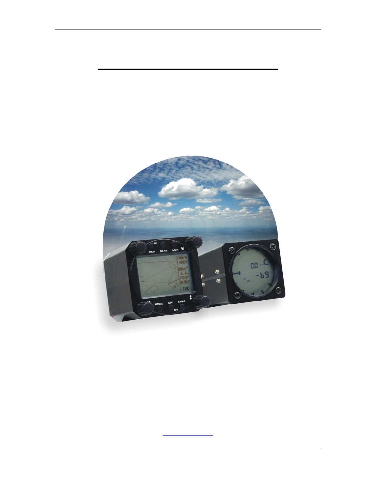
2 General
The instrument consists of two units, the LX 7000 digital unit (80 mm) and LX 7000 analog unit with Vario
indicator (57 mm). Additional LCD Vario indicators can be added any time.
Vario functions
• Vario, Netto, Relative and average
• Speed command
• Final glide calculator
• TE compensation (tube or electronic)
Navigation functions:
• Jeppesen airport and database for Europe (up to 5000 airports)
• 600 turnpoints
• 100 tasks
• Statistic
• Near airport function
• Logger under IGC rules (not approved)
2.1 System configurations
2.1.1 LX 7000 basic
The system consists of:
• LX 7000 digital unit without GPS receiver with NMEA input, connector for direct connection of Colibri and
LX 20
• LX 7000 analog unit with LCD vario indicator
2.1.2 LX 7000 standard
• LX 7000 digital unit with built in GPS receiver
• LX 7000 analog unit with vario LCD indicator
2.1.3 LX 7000 IGC
• LX 7000 digital unit without GPS receiver, connected with Colibri BB (black box) IGC approved logger
• LX 7000 analog unit and LCD vario indicator
Page 4
Page 5
2.2 Technical data
• Power 8-16 V DC
• Consumption 400mA/12V (without audio)
• 80 mm std Aircraft cutout main unit.
• 57 mm std. Aircraft cutout LCD unit.
• Length 110 mm (exc. connector)
• NMEA output
• Winpilot interface
• 12 Channel GPS receiver (LX 7000 standard)
• External speaker
• Data compatible with LX 20 and Colibri.
• PC communication
• Wiring
• Additional LCD Vario could be connected via 485 bus
• Weight: 800g
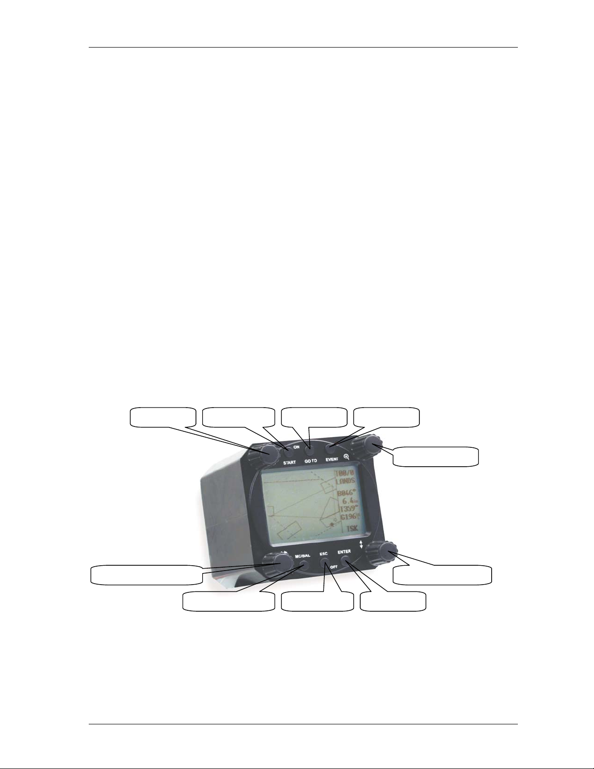
2.3 Rotary switches and keys (buttons)
• four rotary switches (selectors)
• six keys (push buttons)
LCD Vario indicator of LX 7000 analog unit hasn’t any controls
LX7000 Mar.2002
Mode selector r. switch
EVENT keyGO TO key ON/Start key VOL control
ZOOM r. switch
UP/DOWN r.switch
ENTER keyESC/OFF keyMC/BAL input key
Page 5
Page 6

LX7000 Mar.2002
2.3.1 On/Start key
A short press on ON/Start key will switch the instrument ON. To switch the instrument off hold ESC/OFF key for a
few seconds and the instrument will be switched off. To switch the instrument off during the flight needs a
confirmation from the pilot, not to be switched off by mistake.
IMPORTANT!
After having a short power brake during flight and the instrument will be off for a few seconds, it will not produce
two flights.
During flight the key is used to start the task, to see more character of airport name and to step one step back if the
edit menu is active (see paragraph APT).
2.3.2 Mode selector ⇔ (rotary switch)
The ⇔ is used to change modes of operation. This switch has the highest priority in the system. Whenever it is
activated a mode changeover will happen.
2.3.3 Up/down selector v(rotary switch)
This rotary switch has lower priority than ⇔ switch and is active all the time in the selected mode. It is mainly used
for selecting sub menus during navigation and to scroll in edit menu.
2.3.4 ENTER key
The main function of that key is confirmation and to start edit procedures.
2.3.5 ESC/OFF key
It is a multifunctional key, which has two main functions.
• After ESC a jump to one menu higher will follow
• By input of letters and numbers (blinking cursor) ESC confirms the whole row (not necessary to press ENTER
few times)
IMPORTANT!
Longer press on ESC/OFF will switch the unit off. During the flight an additional warning will be activated and
switching off will follow after confirmation.
It is not possible to switch the unit off from SETUP.
2.3.6 ZOOM (rotary switch)
This is a multifunctional rotary switch. Its main function is changing the zoom level in graphic mode.
Additionally the zoom switch is used as follows:
• To select turnpoints (only in TP main page)
• After a mistake by edit it is possible to go back rotating this knob (only by blinking cursor)
Page 6
Page 7
LX7000 Mar.2002
2.3.7 Event key
After activation the logging of the LX 7000 will be faster for a predefined time (see setup/logger). For LX 7000 IGC
users pressing of event will activate the same procedure in Colibri BB.
2.3.8 MC/Bal key
The key is used for MC and ballast input, after first press the MC input will be offered like a window inserted into
the display. Rotating v will produce changes of the MC.
Second press on MC/Bal key will activate ballast input, use the same procedure like by MC.
2.3.9 GO TO key
The pilot is able to make some modes invisible (setup/hidden modes). After doing that all mentioned modes are
running in background and are not available rotating ⇔. To activate such a hidden mode GO TO key should be
used. After pressing a table of all LX 7000 modes will appear on the screen and the pilot will be able to select (v)
believable mode and activate it after enter.
Page 7
Page 8
LX7000 Mar.2002
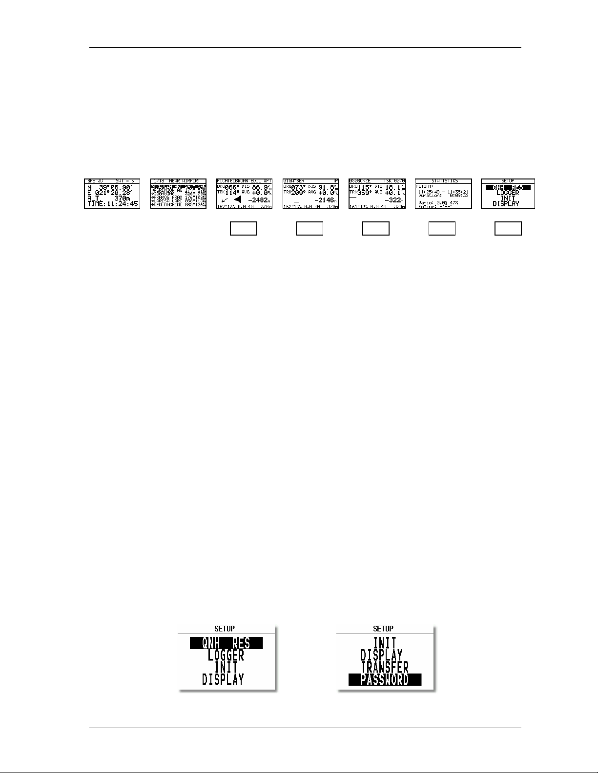
3 Operation modes
The LX 7000 has 7 modes or main menus. All of them are selected directly by rotating the ⇔ or by GO TO key.
The diagram shows us the menu (mode) structure of LX 7000.
⇐MODE⇒
GPS NEAR APT WPT RTE STATISTIK SETUP
⇓ ⇓ ⇓ ⇓ ⇓
⇓ ⇓ ⇓ ⇓ ⇓
Navigation menus (APT, TP, TSK) have sub menus, which are selected using v.
GPS GPS status no input
NEAR Near airport no input
APT Navigation and selection of airports
TP Navigation, selection and edit of turnpoints
TSK Navigation, selection and edit of task
STAT Flight statistic and logbook
SETUP is organized in two levels. The first level (no password required) is accessible for everybody. For the second
level, the pilot has to use the password. The password is not a top secret; it is the same for all instruments and
published.
96990
After installation it is necessary to activate the password and adjust the instrument settings and desired units.
3.1 SETUP
3.1.1 SETUP before password
Changes can be made at any time. This first level contains no system settings at all.
v will select corresponding sub menus.
Page 8
Page 9
LX7000 Mar.2002
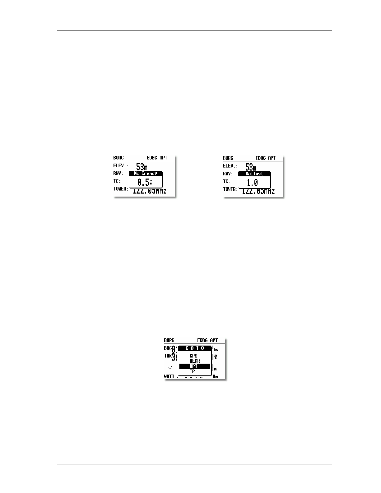
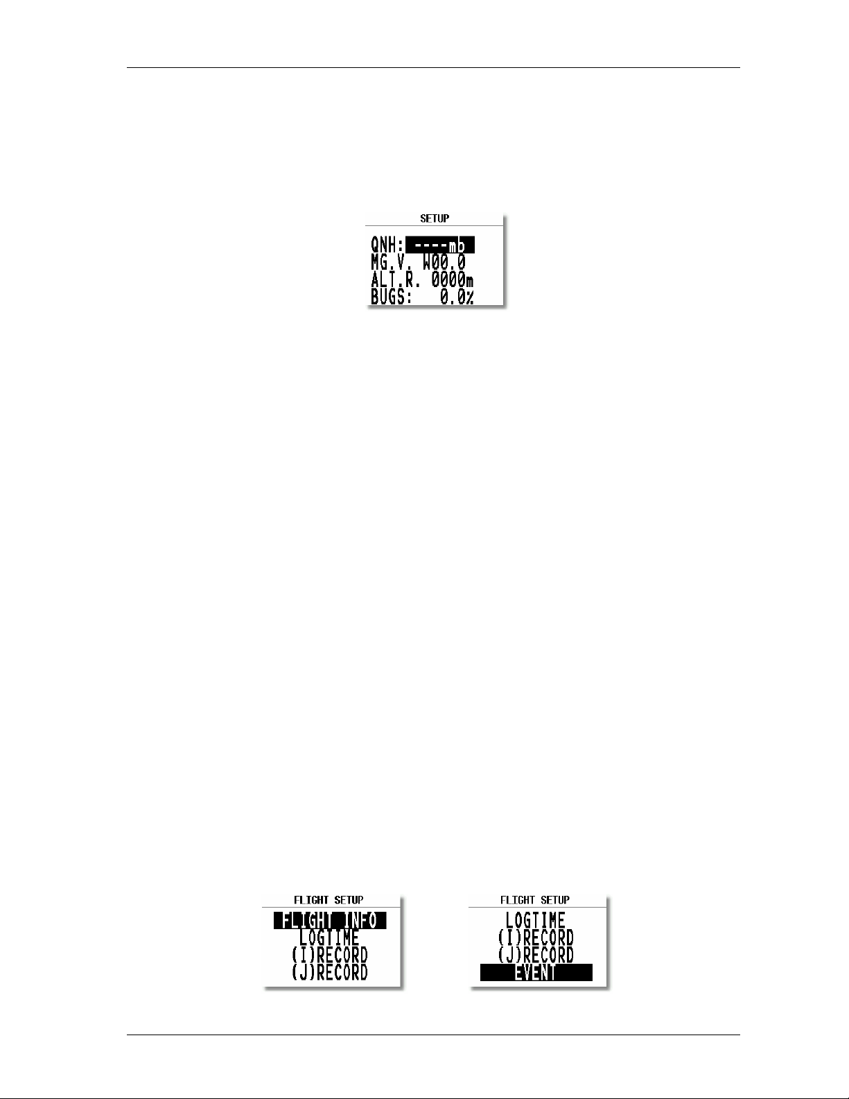
3.1.1.1 QNH RES (QNH and safety altitude)
After switching on, the pilot has an opportunity to input actual QNH, taken from meteorological service. Using this
feature it is possible to offset the altitude during the flight. Without input of initial QNH before the flight, this
function is not active.
Procedure:
• Using the v choose the item (QNH, ALT.R. MG.VAR. or BUGS)
• Press ENTER
• Use v and ENTER for input
• Close the procedure with ESC
Some GPS receivers don’t deliver mg. variation. In that case the input of local variation is obligatory, especially if
magnet compass is used for wind calculation, or mg. track is used by navigation. Having a receiver delivering
variation, no input is possible (AUTO message will appear)
ALT.R. allows input of safety altitude by final glide, after input the final glide will go higher than calculated by
computer and the arrival should happen on ALT.R. altitude. The final glide difference indicator will be on zero
during the final glide.
“BUGS” is polar degradation because of “buggy” wings. The input is in glide ratio degradation percentage.
(5%, means glide ratio degradation is 5%)
3.1.1.2 LOGGER
As mentioned before, the flight recorder (logger) of LX 7000 fulfills all IGC commission requirements, but is not
approved that means only using LX 7000 IGC configuration will produce FAI accepted flights. For another
configurations of LX 7000 is necessary to use an approved logger like NMEA source for LX 7000.
After “enter” the LOGGER will follow.
Page 9
Page 10
LX7000 Mar.2002
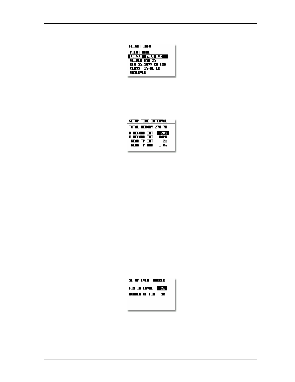
The following data is stored under FLIGHT INFO:
Observer input is not necessary.
LOGTIME is an important setting for sufficient flight recording.
TOTAL MEMORY is the capacity of memory and depends on settings only. This number is not reduced after
some flights are stored. It changes only after new settings have been made in setup. The total memory indicates
how many hours of flight can be flown without loosing the flight data because of overwriting.
B-RECORD: position, GPS altitude, pressure altitude, UTC and GPS status are recorded
Pilot sets record interval, the default value is 12 seconds.
K-RECORD: not active now
NEAR TP INT.: being close to the turnpoint (inside NEAR RAD) the logging runs faster
NEAR TP RAD.: radius that defines NEAR
(I) and (J) (RECORDs are not active)
EVENT
After pressing EVENT key, the logger will run a limited time faster like defined in LOGTIME. Activation of
EVENT is recorded like a special record in the IGC file. Some competition rules require using EVENT before
departure.
Example: after EVENT, 30 additional fixes will be logged in 2-second interval.
Page 10
Page 11
LX7000 Mar.2002
Important!
LX 7000 IGC activates event in Colibri BB automatically after activation on LX 7000 unit digital (EVENT key
pressed) happens.
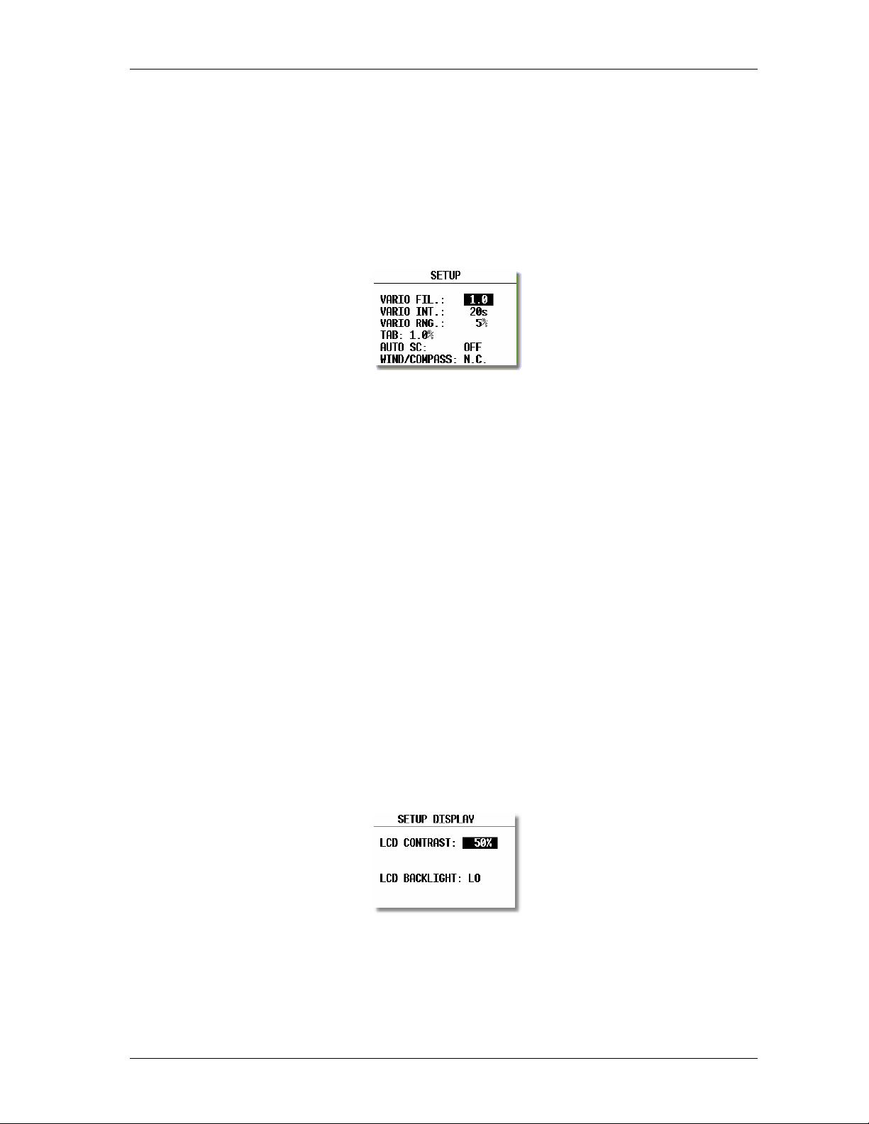
3.1.1.3 INIT
The following parameters can be redefined using this setting.
• VARIO FIL: damping of vario indicator 0,5 up to 5, a normal setting would be 3
• VARIO INT: vario average time, 20 seconds default
• VARIO RNG: vario range
• TAB: audio dead zone by speed command
• AUTO SC: speed command change-over automatic
OFF only with external switch
GPS, after climbing (circling) is detected using GPS, an automatically change over will happen
IAS in 5 km/h steps from 100 up to 160 km/h
• WIND/COMPASS: compass is an optional device which can be connected to the LX 7000 485 bus. The device
delivers magnetic track, using compass an additional wind calculation method can be used. The method needs a
straightaway flight. The time for calculation is set using this menu (normal 15 seconds). Longer time means a
better wind calculation.
3.1.1.4 DISPLAY
The contrast depends on the viewing angle of the pilot. To adjust it use this setting.
To change the contrast rotate v.
Page 11
Page 12
LX7000 Mar.2002
3.1.1.5 TRANSFER
To communicate with PC, LX 20 or Colibri use this menu. Data transfer is started after ENTER, for detailed
information see paragraphs further on.
3.1.1.6 PASSWORD
96990
3.1.2 SETUP after password
After password input
that means after ENTER on password the LX 7000 jumps directly into the setup menu!
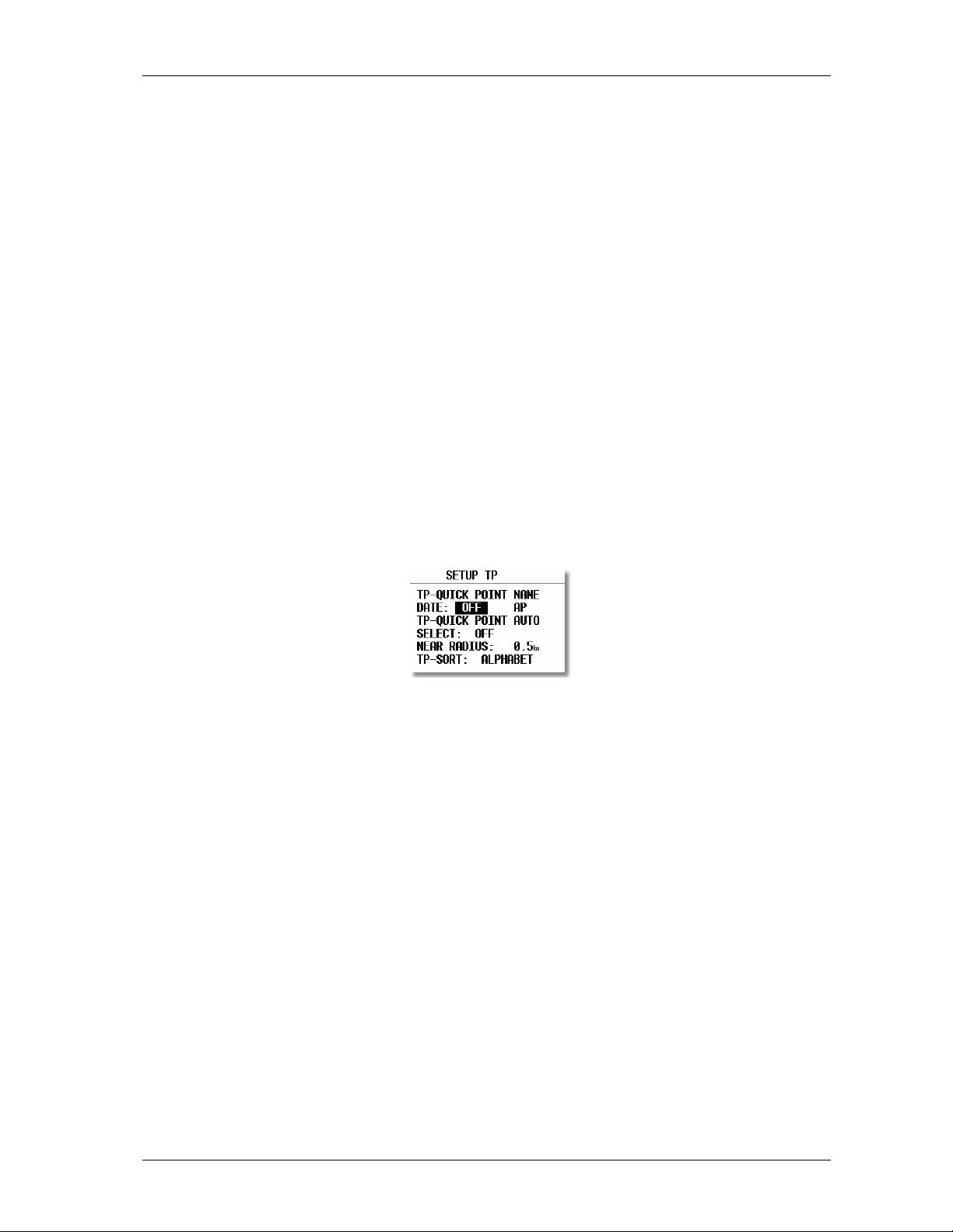
3.1.2.1 TP (Turn point)
All settings about turnpoints can be done in this menu. The LX 7000 is able to store 600 turnpoints.
(96990) further 19 system settings are available. During the flight the password is inactive,
TP-QUICK POINT NAME
The pilot is able to store his actual position during the flight. Such turnpoints are called QUICK TP and are
generally named like AP (actual point). How to store the actual position will be described later. Setting
DATE OFF will store the position like AP: 12:35. The numbers shows the time of storing. Setting
DATE ON will store the position under date and time (28121330 for 28 dec. 13:30).
To store the actual position, the START key should be pressed in TP mode.
TP-QUICK POINT - AUTO
SELECT: OFF after stored, the actual position will not be selected automatically
SELECT: ON after stored, the actual position will be selected automatically and ready for navigation
NEAR RADIUS
The setting has nothing to do with the setting described in LOGGER. The LX 7000 has a very useful function
named „Simple task“. This function is inactive when a regular task is started. The instrument will detect being close
to the turnpoint and after reaching of distance smaller than NEAR RADIUS, the turnpoint will be taken like a
confirmed TP of simple task. Simply said, flying from TP to TP (or APT) would build a nice in-flight statistics and
useful flight evaluation on the ground. For more information on this see Fly LX 7000.
Page 12
Page 13

LX7000 Mar.2002
TP-SORT
The LX 7000 is able to sort the turnpoints under alphabet or under distances (some kind of NEAR TP function).
Being sorted under distance the nearest TP will appear, after starting of select procedure.
3.1.2.2 OBS. ZONE (observation zone)
Following confirmation procedures can be defined:
• Start zone
• Turnpoint confirmation procedure
• Finish procedure
• FAI photosector or cylinder templates
START ZONE
All procedures can be defined using two angles and two radiuses (A1, A2, and R1, R2). With HDG the orientation is
described. Angle A21 is by some settings defined automatically (AUTO) and sometimes it is free.
Combination of photo sector and cylinder
TO NEXT PNT: orientation to the next TP (A21 is auto)
R.FROM 1.TP: radius from 1. TP going through start point. The start line is like a circle segment.
Example R.from 1. TP
A21 doesn’t matter, A1 doesn’t matter, R1 circle segment in km, A2 doesn’t matter, R2 brightness of the sector
in km
FIXED VALUE: free programmable through A21
Page 13
Page 14

POINT ZONE
The logic is completely the same with some more choices for heading:
• SYMETRAL : Symetral between two legs
• TO PREV.PNT : To the previous TP
• TO NEXT PNT : To next TP
• TO START PNT: To start always
• FIXED VALUE : Programmable
FINISH ZONE
Only two settings:
• TO LAST LEG
• FIXED VALUE
TEMPLARES
Using templates will always bring back FAI photo sector or 500 m cylinder.
LX7000 Mar.2002
IMPORTANT!
All settings described above can be prepared using Lxe PC program (ZONES) and simple transferred to the
LX7000.
The LX 7000 meets the latest regulations flying a task by competition, for instance Assigned Area Task. For more
information see paragraph 3.2.5 Task.
3.1.2.3 GPS
The pilot is able to set local time for his navigation.
IMPORTANT!
UTC offset has absolutely no influence on time logged in the logger. Logger always uses UTC.
GPS earth datum is set to WGS 84 and not possible to be changed. GPS at switch on shows the Status of GPS
engine (internal or external) after switching on the unit. All necessary settings are done in the factory.
Page 14
Page 15

3.1.2.4 UNITS
Practically all known units and combinations can be used in the LX 7000.
• LAT, LON: decimal minutes or seconds
• DIST: km, NM, ml
• SP (speed) km/h, kts, mph
• VARIO: m/s, kts
• HDG: magnetic or true
• WIND: km/h, kts, mph, m/s
• ALTITUDE: m, ft
• QNH: mb, mm, in
• OVERLOAD: kg/m2, lb/ft2
Glider + Pilot + Ballast
OVERLOAD= --------------------------------
Glider + Pilot
Example:
Overload 1.2 means that the take of weight is 20% higher than unballasted.
LX7000 Mar.2002
3.1.2.5 GRAPHIC
The graphic display of the LX 7000 offers valuable information, selected by the user. In order not to overload the
display some care should be taken by enabling of airspace.
SYMBOL
The LX 7000 graphic supports two sizes of glider symbol in graphic. Rotate v to select the symbol.
Page 15
Page 16

LX7000 Mar.2002
AIRSPACE
This is a very important setting, which allows the pilot to define under what conditions the airspace will appear on
the display. The instruments are delivered with airspace ENABLE. There are 5 different types of airspace. Each has
different type of line to allow visible separation of different zones. The zones can be present all the time (setting
ON) or closed by setting OFF. Using setting ON for all kinds of airspace will overload the display, so we offer to
use settings, which are connected with zoom. The presence of individual airspace is connected with ZOOM (if not
ON or OFF).
Example!
Using setting for instance 50 km will make the airspace visible only by zoom 50 km and lower. If the zoom is
bigger than 50 km the particular airspace will not be visible.
Factory suggests settings described above.
• CTR. control zone
• R.P,D restricted, prohibited, dangerous
• TRA training zone
• TIZ traffic information zones
• TMA terminal zone
APT
The airports are displayed like symbols with names.
APT ZOOM: 50 km setting will show the airports only having zoom 50 km or lower, if the zoom is bigger than 50
km the airports will disappear completely not to overload the display (available settings ON, OFF, 5,10, 20, 50, 100
km)
APT NAME: The airports are not displayed only with symbols, some letters of the name or ICAO code can be
added. The pilot is able to choose between:
• ICAO will show ICAO code of the airport close to the symbol
• 2char. up to 8 char. will display first letters of the airport
• NONE, without letters, only symbol
Page 16
Page 17

LX7000 Mar.2002
TP
The same logic is taken by displaying of turnpoints.
There are four types of turnpoints and each type has different symbol on the screen.
• T. POINT, simple turnpoint (landing isn't possible)
• AIRPORT, turnpoint with all airport functions
• OUTLAND, turnpoint as an outlanding place
• MARKER, is not a permanent turnipoint, is deleted after the instrument is switched off. It can be used to mark
thermals for instance.
IMPORTANT!
The turnpoints marked landable will appear in the NEAR AIRPORT, displayed with corresponding symbols in front
of the name (airport, outlanding).
3.1.2.6 NMEA
LX 7000 delivers position data in NMEA form to other navigation devices in the cockpit if necessary.
All NMEA sentences are not active in default setting, that means the pilot has to activate them if necessary.
Normally GGA, RMC, and RMB are used. The pilots using Winpilot should activate LXWP_ also.
The data is available like Tx line on 9P sub D connector marked RS 232, see wiring.
3.1.2.7 PC
The speed of data transfer between LX 7000 and other devices (PC, LX 20 or Colibri) can be adjusted in this menu.
It is very important that both devices have the same communication speed.
Page 17
Page 18

LX7000 Mar.2002
The new Windows PC program Lxe is able to adapt the communication speed automatically. The old DOS
programs (LXGPS and LXFAI) are not able to do that.
3.1.2.8 DEL TP/TSK
After Y all turnpoints and tasks will be permanently deleted.
3.1.2.9 POLAR
Polars of nearly all gliders are in the library. To select them simply rotate v to the right and the gliders will appear.
The parameters a, b, and c of the glider polar can be calculated very simple by pilot, if the glider polar is not found
in the library. After LXPOLAR program is started and three points of the polar (Apr. 100 km/h, 130 km/h, 150
km/h) are entered, the parameters are calculated automatically. The LXPOLAR is delivered on the CD together with
LXe. There is space for two USER polars (rotate v to the left).
Name „user“ can of course be replaced with the glider’s name.
3.1.2.10 LOAD
Normally the ballast setting is brought to minimum after the LX 7000 has been switched off. Using setting
SWITCH ON LOAD: SET, the load setting will remain the same as the last setting done in the previous flight.
Page 18
Page 19

LX7000 Mar.2002
3.1.2.11 TE COMP.
The LX 7000 offers two methods of vario TE compensation.
• TE tube
• Electronic TE compensation
TE setting 0% declares compensation using the TE tube
Using the tube the instrument has no influence on compensation; it depends only on quality of the tube.
TE setting >0% = electronic TE compensation
To adjust TE composition minimum one flight in not turbulent atmosphere is necessary. The procedure is as
follows:
• Accelerate up to 160 km/h and keep the speed stable for a few seconds
• Reduce the speed rapidly to 80 km/h
Observe the vario indicator during the maneuver. At the beginning (160 km/h) vario will stay stabile by Apr. –2 m/s.
After speed reduction the vario should move toward zero and should never exceed zero. Indication in + shows that
the compensation is to low, increase % and opposite.
TEF (filter) is delay of compensation and bigger numbers will increase the delay and opposite. The first test
provides using delay 6.
If the static of the glider isn’t correct, there is no way to adjust compensation. Having problems we suggest the
following test of the static inputs:
Connect the tubes for the electronic compensation and set at 0%. Accelerate to 160 km/h and reduce the speed.
Observe the vario indicator. If the needle is moving at first more into minus and after that towards zero, the static of
the glider is not correct and there is no way to provide a successful el. TE compensation.
3.1.2.12 INPUT (Speed command external switch)
The LX 7000 has input for an external speed command switch. Using the external switch it is possible manually to
change over SC/Vario. SC INPUT setting defines what status of the switch will change over to speed command. For
instance ON will change over to speed command immediately after the external switch will be closed and opposite.
An external device called stall warning can be connected to the LX 7000. The indicated speed, to activate the alarm
can be set under STALL W.
The LX 7000 is equipped with an external temperature sensor. Temperature ON will enable temperature
measurement and TEMP. OFF allows adjusting (by user) the temperature precisely.
Page 19
Page 20

LX7000 Mar.2002
3.1.2.13 LCD IND. (LCD – vario indicator)
The LCD vario is an integral part of the LX 7000 analog unit and has address INDICATOR 1definitively. Next units
could be connected via 485 bus and ordered like options. Using bus, generally an unlimited number of devices can
be connected to the LX 7000. The LX 7000 delivers 4 different data sets for the indicators, that means maximum 4
indicators are able to indicate different and the rest of them are simple repeaters.
To adjust viewing angle use contrast setting from LOW to HIGH. The layout of the indicator consists of:
• Needle
• Two numerical displays
• Diverse symbols
LOW BATTERY
INDICATOR
BUGS
INDICATOR
UPPER
NUMBER
DISPLAY
VARIO MOD E
INDICATOR
NEEDLE
SPEED
COMMAND
RING
NEEDLE
SHOWS
VARIO NE EDLE
SHOWS
RELAT IV
NEEDLE
SHOWS
NETTO
NEEDLE
SHOWS
SPEED
COMMAND
• Needle
• SC Ring Always SC indicator, regardless of mode.
• Upper Number Display
• Vario Mode Indicator
• Lower Number Display
• Netto
• Relative
• SC
• GP
SPEED COMMAND
MODE INDICATOR
LOWER
NUMBER
DISPLAY
Page 20
Page 21

LX7000 Mar.2002
Each external indicator has a DIP switch on the backside. The position of the switch defines which data string the
indicator controls.
SW 1 ON Indicator 1
SW 2 ON Indicator2
SW 3 ON Indicator3
all OFF Indicator4
All delivered indicators are default set to position 1.
The pilot is able to define the functions of the indicators by himself using the following menu.
Needle and two numerical displays are programmable. All settings should be done for vario and speed command
mode separately (VAR NEEDLE =needle in vario mode, SC NEEDLE is needle in SC mode).
Needle settings:
• Vario, SC, NETTO, RELATIVE (netto – 0.7 m/s),
Upper digital display:
• Integrator, time, flight time, leg time
Lower digital display:
• ALT (NN altitude), distance, GL DIF. (final glide altitude difference), SPEED (TAS), LEG S. (speed on leg).
3.1.2.14 COMPASS
This unit is optional and has to be ordered extra. Power and data are connected via standard LX 7000 485 bus.
Without a compass unit connected, the COMPAS setting is not active, the LX 7000 will recognize it automatically.
Compass is used to deliver mg. track to the LX 7000. Having mg. track an additional wind calculation method can
be used and HDG indication will be present.
3.2 Navigation functions
The LX 7000 has the following nav. functions:
• GPS Status and coordinates
• Near Airport
• APT, Airport
• TP, Turnpoints
• TSK, Task
• STATISTICS separately during the flight and after flight
All mentioned functions can be selected using ⇔.
Page 21
Page 22

3.2.1 GPS page
There are no settings possible in this page.
Rotate v and both altitudes (m and ft) will appear on the same screen.
Stop watch can be activated and deactivated under following procedure:
• Press START status STOP: 0: 00
• Press START status RUN: 0:12
• Press START status STOP: 0:50
• Press START status STOP: 0:00 Reset
• Press ENTER TIME: 11:56:32 Time again
LX7000 Mar.2002
Battery voltage ind 11V empty
3.2.2 NEAR AIRPORT
The nearest airports will be shown using this mode. The airports are separated under distance and simple press on
ENTER will change over to APT mode and all nav. features will be immediately present. To select the airport use
v.
Outlanding place
Airfied from TP database
Airfied from APT database
IMPORTANT!
Not only airports are in the library, but all landable turnpoints too. The airports and landable turnpoints are
displayed with different symbols in front of the name. For more information see paragraph turnpoints.
Page 22
Page 23

LX7000 Mar.2002
3.2.3 APT Airports
This is one of three main navigation modes (APT, TP, TSK). To change the mode simple rotate ⇔ or use GO TO
function. The first page shows the basic navigation data (bearing, distance, ground track and vario average (AVG) or
netto (NET in SC). Additional information will follow in three more nav. pages activated using the v. The airport
memory of LX 7000 has a capacity for approx. 5000 airports. The airport data can’t be edited in the instrument; all
necessary updates should be done using PC. The database used in LX 7000 is Filser licensed Jeppesen database. The
database is not free, that means an update is possible only after getting a code. The code is available through Filser
Electronic only and depends on the database version and serial number of the LX 7000. The database can be
downloaded from the Internet using the following addresses:
www.filser.de
www.lxnavigation.si
3.2.3.1 Navigation in APT
There are four navigation pages and the first one has the following structure.
Wind vector
Wind direction/speed
The airport names are normally displayed using 8 characters, after pressing START 12 characters will appear.
Final glide difference altitude
Altitude NN
MC and ballast
IMPORTANT!
TP and TSK have the same basic navigation pages as APT.
The arrow (Dir. Indicator) will show the pilot where to turn (left or right) to proceed to the airport.
After rotating the v, graphic page will appear. The same page can be found in TP and TSK too.
The airports will be present with symbols and short names or ICAO corresponding to setting in 3.1.2.5.
Page 23
Page 24

LX7000 Mar.2002
Groundsp.
ZOOM
The glider symbol is all the time in the middle of the screen and the map is moving. To change the ZOOM simple
rotate the ZOOM knob left or right. Following nav. page can be disabled like Nav. page 3.
Estimated time enroute
Estimated time of arrival
ETA estimated time of arrival
ETE estimated time enroute
If there is no way to reach point (difference BRG/TRK more than 90°), both times will be replaced with stars.
The last page shows the pilot some important airport data.
Battery voltage
The traffic circuit is defined like altitude and orientation (N, E…). Orientation I means that it hasn’t been defined.
RWY extension shows runway surface, G like grass and C like concrete.
Page 24
Page 25

LX7000 Mar.2002
3.2.3.2 Airport selection, team function and wind calculation
After ENTER an edit menu will appear.
3.2.3.2.1 Airport selection
There are two ways to select an airport. The first direct way is using of ICAO code input. After code input the
airport is selected immediately.
By mistake use START button (or ZOOM) to step back. By unknown ICAO the indirect way should be used.
Simply confirm ICAO with ESC and select the state in which the airport is (v).
After the state is selected four stars are to be replaced with first four letters of the airport. All airports with the same
first four letters will be shown, use v to find the right one.
If you input less than four characters the offer of the airports will be bigger. Confirming all stars with enter or simple
after ESC all airports of the state will be present.
Page 25
Page 26

LX7000 Mar.2002
3.2.3.2.2 TEAM function
This special function is developed for the pilots flying in the team. Sometime they loose visual contact and using the
Team function they are able to locate each other in a very simple way. To be successful both pilots have to select
the same point (APT, TP or TSK). The pilot who is ahead has to explain his bearing and distance to the selected
point by radio. The second pilot has to activate Team function (enter) and input the distance and bearing given by
his friend.
EXAMPLE!
347° and 24,1 km are data given by the leading pilot.
After input and ESC the instrument will change over into normal TP navigation page and the navigation data will
show where the leading pilot is.
Team f. indicator
The team function is deactivated after a new TP is regular selected.
3.2.3.2.3 WIND calculation
The LX 7000 is able to calculate wind (direction and speed) under 5 methods all the time. Another method
(COMPASS) is available only after an additional compass unit is connected to the LX 7000 bus. To change the
method of calculation, use this menu as follows.
GS is the simplest method. The calculation based on ground speed changes affected by wind influence during the
climbing. To get the first result a minimum of two full circles are necessary. The message WAIT2 or WAIT 1will
inform the pilot how many circles should be done to get the result. It is very important to keep the speed constant
(during the climbing) as much as possible to get real results. The pilot is able to adjust the wind using manual
corrections.
POS is sometimes the best method. It is based on position offset instead of wind during the climbing. To get results
6 turns should be done (WAIT 6).
Page 26
Page 27

LX7000 Mar.2002
COMB is based on special algorithms. The inputs are groundspeed and TAS. The algorithms will calculate the wind
if the glider is slowly changing his track (not exactly straight flight) or by climbing.
COMPON is delivering only wind component (head or tail wind). The calculation is simply based on difference
GS-TAS. It works exclusively during straight flight.
FIX is not a real calculation it allows the pilot simply to input the wind.
COMPASS wind calculation method is available only with external compass device. On how to use the unit see
COMPASS manual.
3.2.4 TP (turnpoints)
The LX 7000 has memory to store up to 600 turnpoints. The turnpoint name can have max. 8 characters (letters or
numbers). The menu structure is the same like by APT that means four pages. To add a turnpoint into the database
select one of these four ways:
• Manual
• Copy from APT
• Data transfer from PC, LX20, Colibri (well known DA4 format)
• Memorizing of actual position
3.2.4.1 TP select
The procedure is similar to the procedure selecting APT. After pressing ENTER menu for SELECT, EDIT, NEW,
DELETE, TEAM and WIND will open. To select turnpoint simple replace stars with the first letters of the TP.
IMPORTANT!
The LX 7000 is able to sort the turnpoints under distance too (definition in setup). Using sorting by distance the
nearest TP will appear after selection (all stars confirmed with ESC). To search for the TP use v and confirm with
ENTER. Default setting is sorting by alphabet.
It is also possible to select TP by using ZOOM selector. It works exclusively from the first page. To change the TP
simply rotate the ZOOM selector.
3.2.4.2 TP EDIT
Using this function the pilot is able to change TP data any time. The turnpoints in LX 7000 have four attributes.
Using attributes the turnpoints will appear in the graphic screen marked with special symbols.
The four different types of turnpoints are as follows:
• T.POINT normal TP not landable
• AIRFIELD landable airfield
• OUTLAND landable outlanding place
• MARKER not landable (will disappear after switching OFF)
TP having airfield and outland attribute are landable and shown in the NEAR AIRPORT mode. In front of the
name the pilot will find the symbol to know what kind of landing place it is (see NEAR).
Page 27
Page 28

LX7000 Mar.2002
To start EDIT press ENTER.
Name, attribute, coordinates and elevation can be altered.
3.2.4.3 TP NEW
There are more possibilities to add a new TP. After ENTER on NEW the procedure is started.
After Y the well-known selection of an airport will follow. The result will be a new turnpoint copied from APT
database. After N manual input of coordinates, name, attribute and elevation will follow.
3.2.4.4 TP delete
After activation of DELETE the TP will be deleted definitively.
3.2.4.5 TEAM
The same as described in APT.
3.2.4.6 WIND
The same as described in APT.
Page 28
Page 29

LX7000 Mar.2002
3.2.4.7 TP QUICK (memorizing of actual position)
Pressing START key in TP only can activate the procedure.
The names of such points are offered in two different forms. AP and TIME or date and time (02100613). The form
depends on setting in setup after password (TP). All data can be edited immediately and stored. This procedure is
useful to memorize convenient landing places, thermals etc…By default settings these points have MARKER
attribute.
3.2.5 TSK (task)
The LX 7000 task consists of maximum 10 turnpoints. The capacity is 100 tasks. Flying a task will offer following
benefits:
• Accurate task statistics
• Simple navigation
• Automatically change over to next TP after confirmation
• TSK shown in graphic
• One step of ZOOM more (full task)
The menu structure is similar to the APT and TP. The pilot is exactly informed about departure, TP confirmation
and finish line. Graphic display is very useful.
And after v
Page 29
Page 30

LX7000 Mar.2002
Approaching to the TP, NEAR message will inform the pilot that he is closing on the turnpoint. After the INSIDE
message is displayed, the pilot is definitively sure that he has reached the observation zone (for inst. photosector).
The tasks are numerated from 00 to 99 and the turnpoints building a task from 0 up to 9. Point 0 is always start point
(departure). TSK select
All memorized tasks can be selected using the select procedure. The procedure is started after choosing the SELECT
and confirmed by ENTER.
To select a task rotate v and confirm with ENTER.
3.2.5.1 TSK edit
The active TSK can be edited at any time, on the ground or during the flight.
After the procedure is started all points of the TSK are shown. After choosing invert Y the task will be inverted. By
pressing ENTER on invert N or Y task edit procedure will follow.
CP is a very important setting. After set (CP) the final glide will be calculated around the turnpoint to the finish.
That means the final glide calculation is ready before the last turnpoint. To edit, select turnpoint with v and press
ENTER.
• after SELECT new TP will replace the previous
• after INSERT a new TP will be inserted one position higher
• after DELETE the TP will be deleted from task
Page 30
Page 31

LX7000 Mar.2002
IMPORTANT!
To follow the latest regulations about task, flying a competition up to five tasks can be prepared in that way. The
pilot is able to input (only by hand) the procedures overhead Start, Tp´s and Finish separately (SETUP/OBS.ZONE
defines the same procedure for all turn points). Up to five tasks from 00 to 99 can be modified that way. It
doesn’t matter task number. Starting EDIT procedure a very typical sign (ZONE) will appear if selected task could
be modified. If there is no ZONE, that means five tasks are already modified. The modified task is active for three
flights. After the third flight is set back to default setting (SETUP/OBS.ZONES). This delay allow the competition
pilot to make three take offs not to loose his individual settings.
Change over after INSIDE
If there is a big observation area around the turn point an AUTO NEXT: N can be selected, that means manual
change over to next turn point. To deactivate all previous settings and to reach five free settings again, is
necessary to use TEMPLATES and all settings will be brought to default. How to fly the task see paragraph Fly LX
7000.
3.2.5.2 TASK new
To build a new TSK an empty TSK should be selected (all points NOT PROG). After COPPY an already existing
task could be copied and edit after, or a completely new task could be created using selection of turnpoints.3
3.2.5.3 DECLARE
The function is by LX 7000 not very important having a not approved for IGC flights. Having in mind that LX 7000
is able to communicate with Colibri and LX 20 will make this function more important. The declaration procedure
substitutes the old method of making pictures of the black board and clock. The declaration should be done before
take off in any way, during the flight is this function not active. Having done the declaration in LX 7000, is possible
to start WRITE FLIGHT INFO and transfer the declaration to the LX 20 or Colibri directly.
All known methods (select, insert, and delete) can be used to change the declaration. Changing of declaration will
not change the TSK.
Normal procedure:
• Prepare TSK in EDIT menu (you will need it for navigation)
• Press ENTER on declare and leave declare using ESC
• Transfer data to Colibri or LX 20 (Flight Info)
Page 31
Page 32

LX7000 Mar.2002
3.2.6 Statistics
This mode is exclusively used to inform the pilot about his actual flight. There are two levels of statistics during the
flight. Flight statistics is always active; the task statistics will be active after a task is started. On the ground only the
logbook is available.
3.2.6.1 Flight statistics
The following data is available during the flight only. After STATISTICS is selected the flight statistics data will
appear on the LX 7000 display.
Take off time
% time spent in climbing
Actual time
3.2.6.2 TSK Statistics
This kind of statistics is present after the task is started (see paragraph Fly LX 7000). Rotating the v will display
statistic data for the individual legs.
Time means TP confirmation time and is normally not present before TP confirmation. For the completed legs the
time is displayed.
Rotating v will show statistics for all completed legs and at the end there will be TSK statistics till actual position.
Page 32
Page 33

LX7000 Mar.2002
3.2.6.3 LOG BOOK
This kind of statistics is available only on ground. The logbook shows the flights under date, take off and landing.
The logbook will appear apr. 3 minutes after landing and this is the sign that the flight is finished.
3.2.6.4 Statistics after flight
The LX 7000 offers flight statistics and flight analyses. To start the procedure select the flight from logbook and
press ENTER.
The distance will appear only after correct declaration.
3.3 Variometer
All analogue signals of LX 7000 (altitude, speed) are derived from high quality pressure sensors, no flask is
necessary. The vario signal is derived from the altitude signal. All signals are temperature compensated. Vario and
speed signals are altitude compensated as wel. A special device based on LCD has been developed for the vario
indicator. Not only vario, but also a lot of additional information is displayed on the unit. The unit is programmable,
that means the pilot is able to preset which information is important for him.
3.3.1 Vario
• range 5,10 and 2.5 m/s 10,20 and 5 kts
• six time constants 0,5s to 5s
• netto vario lift or sink of air mass only
• Relative Vario lift or sink during circling (does not depend on speed)
To compensate the vario there are two ways. The electronic TE compensation based on speed changes with time and
the compensation with TE tube works the mechanical way. Using tube, the LX 7000 has absolutely no influence on
compensation.
Page 33
Page 34

LX7000 Mar.2002
IMPORTANT!
To use electronic compensation connect TE-Pst on static pressure source of the glider
To use TE tube connect tube to TE-Pst
3.3.2 Altimeter
The altimeter of LX 7000 is temperature compensated from -20ºC up to + 50ºC. The altimeter is calibrated from 0
to 6000m, but indication goes up to 8000m. The displayed altitude is always NN (QNH) after correct input of
airfield elevation (set alt.) after switching ON.
3.3.3 Speed command
Speed command is a very useful help to optimize the speed. There are many visual indicators (see LCD Vario).
After the instrument changes to speed command mode, the audio will change and inform the pilot about his speed.
Not to mix vario audio and speed command audio some special features were developed:
• Continuous audio signal in +
• No audio by correct speed (dead band).
3.3.4 Final glide calculator
The final glide calculator calculates the final glide altitude difference to the selected point (APT, TP, and TSK).
Only when using CP in TSK, it will calculate around the last turnpoint to the finish. Indication + will inform the
pilot that the glider is above the final glide and opposite. The final glide depends on MC setting, wind, bugs and
safety altitude.
IMPORTANT!
Elevation of the landing place is incalculated automatically. It is very important o use correct TP database.
Using safety altitude (reserve) the final glide should also show 0m-difference. The only difference is that the glider
won’t arrive at 0m, but at safety altitude. In that case the final glide is simply shifted higher.
3.4 Flying with the LX 7000
It is very important that both, the pilot and the instrument are well prepared for the flight. Doing that, flying with the
LX 7000 will make pleasure and be successful.
3.4.1 Preparation on ground
A good preparation on the ground will not take a lot of time, but will reduce frustration during the flight. After
switching ON the program version and data base version will appear for aprox. 20 seconds. This time is used to
stabilize the sensors.
Page 34
Page 35

LX7000 Mar.2002
3.4.2 SET ALT (take off elevation input)
We all know that air pressure changes all the time. After switching ON, the instrument doesn’t know the elevation
and the elevation should be put in.
SET ALT: 0185 m
The pilot has to input his take off elevation. The instrument will offer the last airport which was on the top list of
NEAR AIRPORT, if it is OK, the pilot simply has to confirm the offered altitude. QNH setting is not mandatory
(ESC to over jump).
QNH:-------mb
After input of QNH the pilot will be able to offset his altimeter instead of pressure changes during the flight. This
will make his flight and specially his final glide safer. The best way to get actual QNH is meteorological service on
the airfield. The input procedure is as follows:
• Rotate v and 1013 mb will be offered
• Use ENTER and v to adjust actual value
3.4.3 Preflight check
It is hardly recommended to check all settings in setup (only before password) especially if more pilots are flying
the glider. All parameters will remain unchanged after switching off, the only exceptions are:
• QNH
• BUGS
• Ballast if not defined like set in setup LOAD
IMPORTANT!
When attempting an FAI badgeflight do not forget to provide „TASK DECLARE“ procedure and transfer
Flight info to Colibri or LX 20.
Declaration during or after the flight is not possible!
3.4.4 How to start the TSK?
Being inside observation zone (photosector, beercan etc…) the pilot is able to start the task by pressing the
START button briefly.
before departure after departure
Immediately after the start is accepted the navigation data will change to TP 01. This is the most important signal
that the task has been started.
The pilot is able to restart the task at any time. After task start edit menu is increased and the RESTART item is on
the top now.
Page 35
Page 36

LX7000 Mar.2002
IMPORTANT!
After restart the task is ready to be started again. Restarting of task has absolutely no influence on
DECLARATION and logging.
It is also possible to start the task outside of the observation zone. The pilot has to hold START so long that the
navigation will change to TP 01 (aprox. 6 seconds)
3.4.4.1 TP confirmation
The LX 7000 will detect „inside“ overhead TP automatically and will change over to next TP .
If the TP will not be reached there are two ways to avoid the TP.
• EDIT task and delete TP (recommended method)
• Hold START so long that the navigation (aprox. 6 sec.) will change to next TP and simple overjump the not
reached TP.
Exceptions are turnpoints declared like part of AAT.
3.4.4.2 TSK END
After reaching the finish zone the task stops automatically. A very typical message TSK END will appear.
It is possible to start a new task (during the flight) after TSK END, using the RESTART procedure.
3.4.4.3 Procedure after landing
FAI regulations requires a straight line by barogram at the beginning and at the end. This is the reason that we
recommend not to switch off the LX 7000 immediately after landing.
A very typical signal that the procedure is finished, is logbook instead of statistics page.
If the unit is accidentally switched off immediately after landing, there will not be any problems.
3.4.4.4 SIMPLE TASK
Simple task is active all the time before a regular task is started. The function is very useful for the pilots who do
not fly a task, but are flying from TP to TP (the same is flying to APT). Simple task will bring similar statistics like
real task and the same holds true for flight evaluation using PC.
Immediately after take off, the current position is taken like start point. Reaching believable TP or APT (has to be
selected in TP or APT) the point is taken like confirmed TP and so on. The radius to define confirmation is set by
pilot in „NEAR TP“. The simple task is growing on simple collecting points. The flight statistics is practically the
same like by regular task. TSK S informs that no regular task is in progres.
After RESTART procedure the simple task will be restarted and present position will be taken as a new start.
Page 36
Page 37

LX7000 Mar.2002
4 PC and logger communication
LX 7000 is able to communicate with:
• PC ( LXe Program, LFAI, Strepla and CAL )
• LX 20
• Colibri
• Posigraph
The following data can be transferred bi-directional (LX20, Colibri, and Posigraph)
• TP and TSK data (DA4)
• Flight information
Using combination with logger the pilot is able to prepare his flight at home, transfer the data into logger and on the
airfield simple use the logger like data source for LX 7000.
4.1 Communication with PC
The communication is established via RS 232 port. To communicate with PC a special cable is delivered with the
LX 7000 (SUB D 9P and 5P round connector).
The CD with following programs is delivered together with LX 7000:
• Lxe Windows program for communication, basic flight evaluation and database management
• LXFAI DOS program for flight evaluation
• Manuals for practically all LX instruments incl. Manual for Lxe
Using Lxe following data exchange can be realized:
• Read logger
• Read da.4 (read TP and TSK)
• Read flight info
• Write da.4 (write TP and TSK)
• Write flight info ( incl. declaration)
• Write APT
• Write airspace
• Write zones (confirmation sectors)
• Read zones ( automatically done after zones activation in LXe)
The next very useful function is transfer of confirmation procedures. The pilot is able to prepare departure, TP and
finish procedure using Lxe and to transfer them into LX 7000. Use menu ZONES in Lxe.
Lxe can also be used for data base update. The data base update is not free (Europe). To provide update the user
needs an update code. The code is available by Filser Electronic. The update code for database, which is delivered
with the instrument, is written on CD cowers.
How to realize CONNECT status?
• LX 7000 / SETUP – TRANSFER
• PC – run PC program LXe)
• LX 7000 ENTER and wait some seconds till CONNECT appears
CONNECT indicates that both LX 7000 and PC established connection and data transfer can be started.
Having problems with connection check the following:
• close all other applications occupying com port (on PC)
• check cable and connector
• disconnect LX20, Colbri or other GPS devices and PDA units occupying communication port
Page 37
Page 38

LX7000 Mar.2002
4.2 Communication LX 7000 – LX 20, Colibri
LX 7000 is able to exchange data (bi-directional) with LX 20, Colibri and Posigraph. The following data can be
transferred:
• DA.4 files (TP and TSK)
• Flight info
To establish data transfer use following steps:
STEP LX 20 LX 7000
1 Main MENU / LOGGER SETUP / TRANSFER
2 ENTER
3 READ or WRITE key Select transfer function (read/write)
4 ENTER
LX 7000 acts like a master and will force LX 20 to follow his commands
Transfer functions (LX 7000)
READ TP/TSK
READ INFO
WITE TP/TSK
WRITE INFO
Read means, LX 7000 will read data from LX 20 and opposite
Communicate with Colibri is much more simple. The Colibri will establish CONNECT automatically after pressing
ENTER on TRANSFER by LX 7000. The CONNECT status is signaled by a sound from the Colibri. Having
activated some NMEA sentances on LX 7000 use following procedure to establish connection.
Colibri LX 7000
Off Transfer/Enter
Off Waiting connection
On (connect) Transfer menu
5 Installation
The LX 7000 Digital unit needs one standard 80-mm cutout. The Analog /Vario needs one standard 57 mm cutout.
Both units are extremely short (110 mm) and therefore not problematically to be installed in any glider.
Three pressure connectors are on the rear side of the Analog/Vario unit. A label on the rear side shows their
functions.
• Ptot = Pitot, Total pressure
• TE = TE probe
• Pst = Static
Using electronic compensation:
• TE/Pst Static
• Pst Static
• Ptot Pitot
Page 38
Page 39

Using TE tube
• TE/Pst TE tube
• Pst Static
• Ptot Pitot
LX7000 Mar.2002
Page 39
Page 40

LX7000 Mar.2002
IMPORTANT!
Having changed Ptot and Static, there will be no integrator (average climbing) indication during the flight
TheLX 7000 digital unit is connected to the power via 15 SUB D connector and the analog part is powered from the
digital unit All connectors re well marked, so there is no reason to be installed wrong. There is no fuse in the
instrument so it is VERY IMPORTANT to use an external fuse (2A). For power supply extension use min. 0.5
mm² cables.
selector axle
special type
inscripted
selecto
instrument
LX7000
LX500
Installation of the LX 7000
• Prepare the cutouts in the instrument panel according to the drilling plans.
• Remove the covers from the four main selectors on the LX 7000 digital unit.
• While holding the selectors, open the screws, which are now visible with a screwdriver. Now the selectors may
be removed.
• Remove the four special type screws.
• Now position the LX 7000 in the cutout in the instrument panel.
• Fasten the LX 7000 with the special screws.
• Now the turn knobs and the covers may be fastened again.
Page 40
Page 41

5.1 Wiring
g
LX7000 Mar.2002
5.1.1 Wiring (standard version)
LX 7000 ANALOG UNIT V1.0 Wirin
8
+12V DC IN
15
7
14
6
13
SC
5
B
12
A
4
SPEAKER
11
RXD
3
TXD
10
2
LX700 0 ANALO G UNIT
9
1
SUBD15 C onnector / fe male
GND
GND
LX 7000 V1.0 DIGITAL UNIT Wiring
+12V DC IN LX7000 POWER IN
GND
LX7000 DIGITAL UNIT
SUBD15 Connector / female
RJ6/6
LX7000
8
15
7
14
6
13
VP
5
B
12
A
4
OUT_TEMPERATURE
11
RXD
3
TXD
10
2
9
1
+12V DC OUT
GND
GND
30 cm
30cm
0.5m
30 cm
150cm
20cm
50cm
150 cm
yellow
red
+12V
white
black
shield
Chinch
AUDIO OUT
yellow
red
+12V
white
black
shield
TEMP
GND
RX
white
TX
black
SHIELD
White RXD
Black TXD
Shield GND
(delivery included)
1
A
6
7
4
B
9
5
1
A
6
7
4
B
9
5
1 2 3
1
6
2
7
3
8
4
9
5
INST. PANEL
1
3
5
09-0097-00-05
BINDER 5Pin Male
PC-RS232C
RS485 - IN
Speak er
SC switch
RS485 - OUT
Important!
Transferring data LX7000 ⇔ Colibri or LX20
(TP & TSK, flight info), disconnect PDA unit
SUBD9 / mal e
(WinPilot).
Reading logger from LX7000, disconnect PDA
unit (WinPilot) and LX20 or Colibry obligatory.
CONNECTED
485 BUS
PC
LX 7000/LX 500 PC CABLE
1
3
5 Shiel d
BI N DER 5 Pi n Fe ma l e
SUBD9 / female
711-2-99-0096-00-005
150 cm
WinPilot
TEMP. SENSOR
LX7000/WINPILOT cable (delivery included)
1
6
10 cm
2
7
3
8
4
RS232
SUBD9 / mal e
RS232
9
5
SUBD9 / female
TX
GND
1
6
2
7
3
8
4
9
5
SUBD9 / mal e
SUBD9 / f emale
WINPILO T RS23 2
RS232 for WINPILOT
Colibri, LX20/2000
1
6
2
7
3
8
4
9
5
SUBD 9 Female
Page 41
Page 42
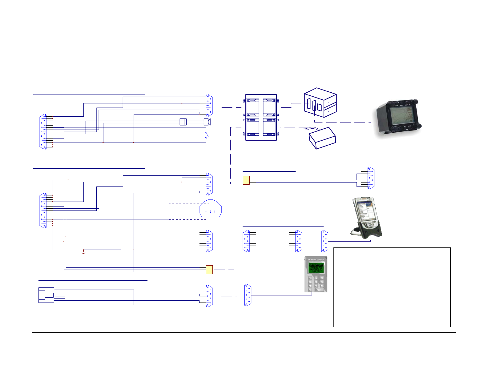
5.1.2 Wiring (optional version)
LX 7000 ANALOG UNIT V1.0 Wiring
8
+12V DC IN
15
7
14
6
13
SC
5
B
12
A
4
SPEAKER
11
RXD
3
TXD
10
2
LX7000 ANALOG UNIT
9
1
SUBD15 Connector / female
GND
GND
LX 7000 V1.0 DIGITAL UNIT Wiring
+12V DC IN LX7000 POWER I N
8
15
7
+12V DC OUT
14
6
13
VP
5
B
12
A
4
OUT_TEMPERATURE
11
RXD
3
TXD
10
2
LX700 0 DIGITAL UNIT
9
1
SUBD15 C onnector / female
GND
GND
LX7000 / LX20 Communication Cable (delivery not included)
TO P S I D E
RJ6/6 - LX7000
1
GND
2
RX
3
TX
4
5
6
12V
GND
30 cm
30cm
0.5m
30 cm
150cm
20cm
50cm
150cm
TEMP
GND
+12V
AUDIO OUT
+12V
RX
TX
SHIELD
RX
TX
12V
GND
Chinch
yellow
red
white
black
shield
yellow
red
white
black
shield
white
black
White RXD
Black TXD
Shield GND
Black
Red
Blue
Whi t e
A
B
A
B
1
6
7
4
9
5
SC sw itch
1
6
7
4
9
5
1 2 3
1
6
2
7
3
8
4
9
5
INST. PANEL
1
3
5
2
3
9
5
485 Spliting Unit (using additional LCD vario and Kompass)
Speake r
485 BUS
RS485 - IN
SUBD9 / male
485 BUS
SUBD 9
FEMALE
MALE
LX 7000/LX 500 PC CABLE
1
3
5Shield
BI N DER 5 Pi n Fe ma l e
RS485 - OUT
SUBD9 / female
TEMP. SENSOR
711-2-99-0096-00-005
LX700 0/WIN PILOT cable (del ivery include d)
1
6
2
7
3
RS23 2
SUBD9 / ma le
09-0097-00-05
BINDER 5Pin Male
PC-RS232C
LX20 RS232
SUBD9 / f emale
8
4
RS23 2
9
5
SUBD9 / female
LX20 RS232
SUBD9 / ma le
SUBD 9
FEMALE
SUBD 9SUBD 9
FEMALE
10 cm
TX
GND
485 BUS
1.5 m
LX20
485 BUS
1
6
2
7
3
8
4
9
5
LCD Vari o
SUBD9 / male
RS232 for WINPILOT
KOMP AS S
WinPilot
SUBD9 / female
WINPILOT RS232
LX7000 Mar.2002
LX7000 D (second seat)
485 BUS
PC
1
6
2
7
3
8
4
9
5
SUBD 9 Female
Important!
Transferring data LX7000 ⇔ Colibri
or LX20 (TP & TSK, flight info),
disconnect PDA unit (WinPilot).
Reading logger from LX7000,
disconnect PDA unit (WinPilot) and
LX20 or Colibry obligatory.
Page 42
Page 43

5.2 Tree-structure-Diagram
LX7000 Mar.2002
Page 43
Page 44

6 Passwords
96990 System parameters
55556 External NMEA input (internal GPS is disconnected)
The function is active till switching OFF or new input of 5556
99999 Delete logger (all logger data will be deleted)
7 Revision history
Version 1.0 New done
LX5000 Jan 2001
Seite 44
Page 45

8 Basic navigation terms
LX5000 Jan 2001
N
TP/APT
Seite 45
 Loading...