

Page 1
Page 2

Document Name:
LX Era 57/80 user’s manual
Version: 0.9H
Page 1 of 52
LX Era
User’s manual
(version 0.9H)
Refers to LX Era 57/80 FW version 0.9H
For standalone use and for use in an LX Zeus configuration.
Tkalska ulica 10
SI 3000 Celje
Tel.: 00 386 3 490 46 70
Fax.: 00 386 3 490 46 71
info@lxnavigation.si
www.lxnavigation.com
Page 3
Document Name:
LX Era 57/80 user’s manual
Version: 0.9H
Page 2 of 52
CONTENTS
PART ONE – INTRODUCTION ............................................................................................................................................... 4
1.1 Preamble .................................................................................................................................................................. 4
1.2 Introduction ............................................................................................................................................................. 5
1.3 Operation ................................................................................................................................................................. 7
PART TWO – INSTALLATION................................................................................................................................................. 8
2.1 Mechanical installation .................................................................................................................................................... 8
2.2 Pneumatic connections ................................................................................................................................................... 8
2.3 Electrical installation ........................................................................................................................................................ 9
2.4 External switch installation ........................................................................................................................................... 10
2.5 Installation options ........................................................................................................................................................ 11
Configurations ...................................................................................................................................................................... 11
LX Era – OUDIE ................................................................................................................................................................. 11
LX Era – Flarm .................................................................................................................................................................. 11
LX Era – Flarm – OUDIE .................................................................................................................................................... 11
LX Era – Flarm – OUDIE – 2nd seat –2nd OUDIE ............................................................................................................... 12
Wirings for radio .............................................................................................................................................................. 13
2.6 Update procedure ......................................................................................................................................................... 14
2.7 Technical specifications ................................................................................................................................................. 14
PART THREE – INTERFACE .................................................................................................................................................. 15
Front panel interface ........................................................................................................................................................... 15
PART FOUR – SOFTWARE................................................................................................................................................... 18
4 Main pages.................................................................................................................................................................. 18
4.1 Vario page .............................................................................................................................................................. 20
4.2 Thermal assistant page .......................................................................................................................................... 21
4.3 Flarm radar page .................................................................................................................................................... 22
Flarm select ............................................................................................................................................................ 22
Flarm warning ........................................................................................................................................................ 23
4.4 TP navigation page ................................................................................................................................................. 23
4.5 Airport navigation page ......................................................................................................................................... 24
4.6 Task navigation page ............................................................................................................................................. 25
4.7 G-Force page .......................................................................................................................................................... 26
4.8 GPS info page ......................................................................................................................................................... 27
4.9 Logbook / statistic page ......................................................................................................................................... 27
Logbook ............................................................................................................................................................. 27
4.10 Statistics ................................................................................................................................................................. 28
4.11 Setup....................................................................................................................................................................... 29
Pilot................................................................................................................................................................ 29
Vario/SC ......................................................................................................................................................... 30
Page 4
Document Name:
LX Era 57/80 user’s manual
Version: 0.9H
Page 3 of 52
Polar .............................................................................................................................................................. 31
Units .............................................................................................................................................................. 32
Indicators ...................................................................................................................................................... 33
Logger ............................................................................................................................................................ 34
Warnings ....................................................................................................................................................... 34
Voice .............................................................................................................................................................. 35
Transfer ......................................................................................................................................................... 36
Inputs............................................................................................................................................................. 39
NMEA............................................................................................................................................................ 40
Pages ............................................................................................................................................................ 41
Password ....................................................................................................................................................... 41
Info ................................................................................................................................................................ 41
Shutdown ...................................................................................................................................................... 42
PART FIVE – CONNECTIVITY ............................................................................................................................................... 43
5 Wi-Fi/Bluetooth module ............................................................................................................................................ 43
5.1 Pairing with PNA and Android devices ................................................................................................................. 43
5.2 Supported data transfers ...................................................................................................................................... 43
5.3 Usage ...................................................................................................................................................................... 43
6 User port ..................................................................................................................................................................... 43
6.1 Supported data transfers ...................................................................................................................................... 44
7 SD card ........................................................................................................................................................................ 44
Additional information ...................................................................................................................................................... 44
PART FIVE – FLYING WITH ERA .......................................................................................................................................... 47
Flight preparation on ground .............................................................................................................................................. 47
Before take off ..................................................................................................................................................................... 47
During flight .......................................................................................................................................................................... 47
Set QNH ............................................................................................................................................................................ 47
Wind calculation .............................................................................................................................................................. 47
Influence of wind in final glide ........................................................................................................................................ 47
Event function .................................................................................................................................................................. 48
Task start .......................................................................................................................................................................... 48
After landing ......................................................................................................................................................................... 48
Downloading flights ......................................................................................................................................................... 48
Revision history ................................................................................................................................................................. 49
Page 5

Document Name:
LX Era 57/80 user’s manual
Version: 0.9H
Page 4 of 52
PART ONE – INTRODUCTION
1.1 Preamble
Why LX Navigation?
LX Navigation is one of the oldest glider navigation brands. Its founders started experimenting with glider
computers way back in the 70's and the Company has been working on improving your flight performance
ever since.
Throughout the last 40 years or so it has been working on instruments that most pilots will have used at
some time. In fact our equipment can be found in almost any gliding club!
Our equipment has always been ground-breaking.
Our motto?
Be the first. Be the best. Be different.
Why Era?
Because Era is the latest breakthrough in the world of electronic variometers. The 3.5’’ large transflective
LCD display will show you the way when flying tasks, cross-country flights, or just plain airfield soaring.
With the Wi-Fi/Bluetooth module inside, you are stepping into the age of connectivity. The Era of
connectivity, if you will.
Always know your position and heading, with clearly visible lift or sink, thanks to our gradient digital needle.
The ERA 80 is a miniature package that includes everything a glider pilot needs, from navigation, to statistics,
AHRS, G-meter, up to the very root of this device – the vario function. All this comes with a backup battery
and IGC certified logger. What more do you need?
Devices
We offer a wide range of instruments suitable for both club and competition soaring.
Our systems combine two components:
First, a glider computer (LX Zeus) which is used for calculating and displaying all of the key information used
by pilots. This glider computer is the brain of the operation.
The second part of the system is a variometer (Era, Helios, and Era). Its job is to gather the information
which the Zeus uses. The vario has pressure connections as well as the GPS antenna connection which is
required for IGC logs.
There is a wide variety of choice for varios and for LX Zeus display sizes.
Page 6

Document Name:
LX Era 57/80 user’s manual
Version: 0.9H
Page 5 of 52
All our varios are standalone devices which can be used without a glider computer for displaying flight
parameters such as final glide information, Speed Command (SC) as well as basic navigation. Our varios also
have an internal battery which means that your IGC logs do not depend on your glider`s batteries.
System extensions (second seat unit, remote control (LX Joy), compass, NavBox, MOP, Flap sensor, AHRS ...)
are also possible. Everything is connected using a CAN bus (single cable for power and data). All connections
are plug and play, which means no specialist is required to install the system.
1.2 Introduction
The LX Era is an “all-in one” standalone speed-to-fly variometer, flight recorder, final glide calculator and
navigation system with an internal backup battery, audio warnings, vario beeps and voice messages.
The unit is capable of providing APT (airport), TP (turnpoint) and TSK (task) navigation on three dedicated
navigational pages. Navigation pages feature Navboxes showing bearing to point, track, distance and final
glide with airspace shown graphically, airports and turnpoints.
The vario is designed to fit a standard 80mm aviation cut-out hole. It is able to supply PDA/PNA units with 5
V/500 mA and 3.3 V/100 mA output on User output connector.
LX Era has built-in high precision digital sensors based on latest MEMS technology for altitude, vario, speed,
3-axis gyro and 3-axis accelerometer sensors. A minimum sampling rate of 100 Hz is applied to all sensors.
The digital needle can be assigned to show one of multiple parameters (vario, netto, g-force, speed command
etc.). By default, it is shows vario value.
As an integral part, it has a 3.5” sunshine readable transflective LCD display to show all user defined data
during flight. For accessing all system options, two rotary/push knobs are used. A voice module is also built in
for audio warnings.
A double seater installation is possible by installing an LX Era Repeater and connecting it to the system via a
CAN bus.
An integral IGC approved flight recorder with ENL level detector will record flight to internal solid-state
memory (8GB). All flights can be copied to an external SD card after flight.
For backup and safety reasons, it has an internal battery which will provide power to the Era for three to five
hours after the main power supply is disconnected. The integral charger will charge the backup battery when
external power supply is connected (12V).
LX Era features are:
- 3.5˝ transflective technology sunlight readable display
- Integrated G-meter (g-forces recorder)
- 3-axis gyroscope
- 3-axis accelerometers
- 50ch GPS receiver as an integral part of the system
- Completely new design using latest pressure transducers technology
- Extremely fast vario data acquisition
- Rotary knob with push function, for simple and effective handling
- Nearly unlimited memory space for flight recorder
- ENL (Environment Noise Level) sensor
- 5 user defined status inputs (SC, VP, gear, brakes and ballast)
Page 7

Document Name:
LX Era 57/80 user’s manual
Version: 0.9H
Page 6 of 52
- OAT probe input (outside air temperature)
- Internal beeper (for Flarm warning)
- Flarm port (input of Flarm data)
- User port for PDA/PNA/Radio/transponder, supplies navigation and Flarm data to PNA/PDA
- Bluetooth interface
- Voice module as an integrated part of the system
- CAN Bus, for connection to LX Zeus or other LX devices.
- External SD Card interface, for firmware updates, flight downloads and TP/TSK/APT/Airspace
transfers
- Standard 80/57 mm size
- The unit can be used as stand-alone, or as a part of LX Zeus system
- Built-in rechargeable battery provides three to five hours of autonomy
- Internal battery (charged from the instrument power supply)
- Pre-loaded polar database
Functions:
- Variometer, TE compensation (TE probe or electronic compensation).
- Speed-to-fly function
- Final glide calculator based on GPS data (for TP and TSK)
- Complete TP/APT/TSK navigation with airspace information and warnings
- High level IGC approved flight recorder
- Flarm radar screen
- Thermal assistant screen
- System extensions: Second seat configuration, Remote control operation (LX Joy)
- Logbook
- Flight information with Barograph
- Multi pilot support
- Accurate wind calculation in straight flight and circling
- Voice alerts
- User warnings
The term "back-up mode" will be used in this manual to define the situation where main power is lost in
flight and the LX Era is used as part of the LX Zeus system. The LX Zeus will turn off, and the LX Era will use
its internal backup battery to continue working. All functions of the LX Era are operational in backup mode
so the pilot can safely navigate back to home or complete the task.
LX Era can be used in two different configurations:
- As a standalone: LX Era provides a vario navigation system and has all its options active. The unit
will turn on when the enter push/rotary knob is pressed.
- LX Zeus configuration: LX Era serves as the vario system controlled from LX Zeus. The unit will turn
on automatically when the main switch (Zeus) is turned on. Flarm radar settings and thermal
assistant settings are set on LX Era while all other settings are controlled by settings on the LX Zeus.
Some options are disabled on the LX Era (setup, task edit) but all options become active when
backup mode is detected.
Unit has the capability to be updated to any later FW release free of charge. (see: www.lxnavigation.si)
When used as a standalone system please refer to Setup/Transfer/Update to learn how to update the
system.
When used as part of a LX Zeus configuration, the LX Zeus will automatically update LX Era if required to
latest version, so no extra action is required.
Page 8
Document Name:
LX Era 57/80 user’s manual
Version: 0.9H
Page 7 of 52
1.3 Operation
Switching the unit on
There are two different ways of turning the unit on.
Standalone units are turned on by pressing the lower push/rotary knob until the LX logo appears.
Varios used alongside a Zeus are turned on automatically when the main unit (the Zeus) is turned on.
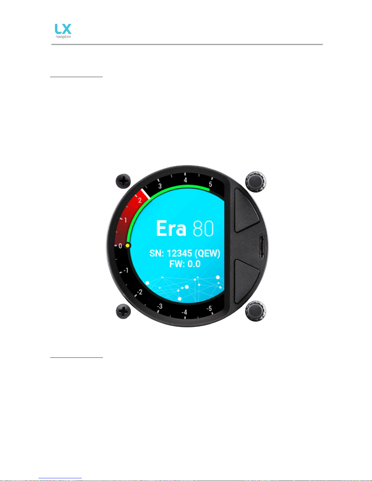
The device name with serial number and software version information will follow after the logo appears. After
the boot procedure, the initial setup with pilot selection and elevation/QNH setup will be shown. If the device
is used with the LX Zeus, the initial setup screen does not appear, since the initial setup is done on the LX Zeus
unit.
Switching the unit off
When on the ground (in this situation the flight recorder will not be running), disconnecting the main power
supply will turn it off. LX Era will start to count down 3 seconds before it turns itself off. You can also turn the
unit off by going to the Setup page and scrolling down to Shut down. After selecting the shutdown option, you
will be asked to confirm. After the confirmation, the unit will perform a 3 second countdown and then turn
off.
In flight mode (in this situation the LX Era detects IAS and the flight recorder will be running) it will not switch
off until the flight has ended, unless the Shutdown option in Setup menu is used. Otherwise, the flight will end
automatically 10 min after landing or if manually selected by the user.
To manually end the flight, refer to the instructions found in the statistics page section.
Page 9
Document Name:
LX Era 57/80 user’s manual
Version: 0.9H
Page 8 of 52
PART TWO – INSTALLATION
2.1 Mechanical installation
LX Era fits in a standard 80 or 57 mm instrument hole so no extra cut out is required. To fit LX Era into the
instrument panel, unscrew the two mounting screws (black) with a screwdriver and remove the two rotary
knobs.
To remove the rotary knobs do not use force. First, remove the press-in cover to access the screw. Loosen
the screw and pull off the knob. Place the LX Era in the hole in the instrument panel and first screw in the
two black screws and then install the two rotary knobs. Do not forget to tighten the screw of each fixing
knob and put the press-in covers back on.
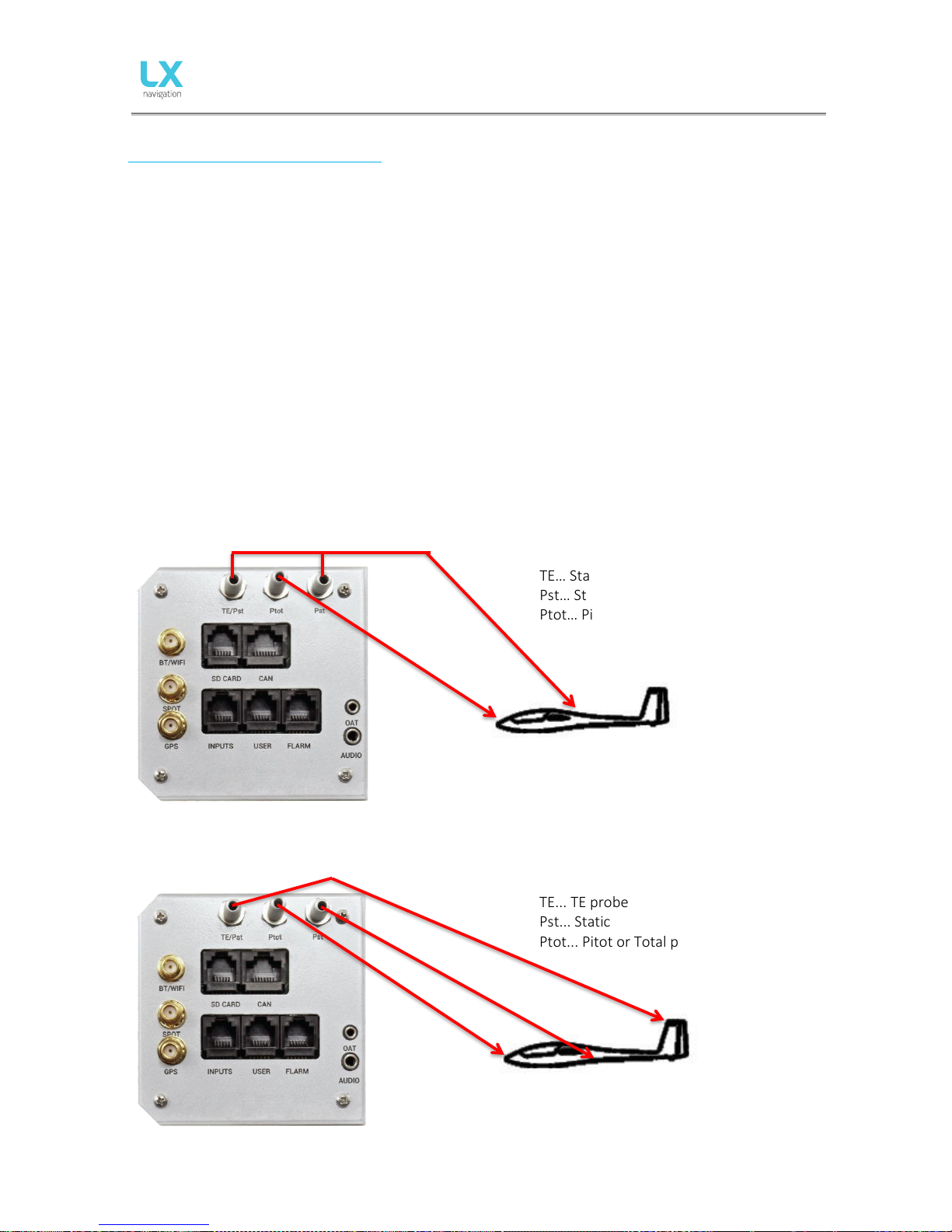
2.2 Pneumatic connections
Three pressure connectors are fitted to the back of LX Era. A label shows their functions.
Ptot = Pitot or Total pressure
TE = TE probe
Pst = Static
Electronic TE compensation schematics (Set TE 100%)
TE… Static
Pst… Static
Ptot… Pitot or Total pressure
TE tube installation schematics (Set TE 0%)
TE... TE probe
Pst... Static
Ptot... Pitot or Total pressure
Page 10
Document Name:
LX Era 57/80 user’s manual
Version: 0.9H
Page 9 of 52
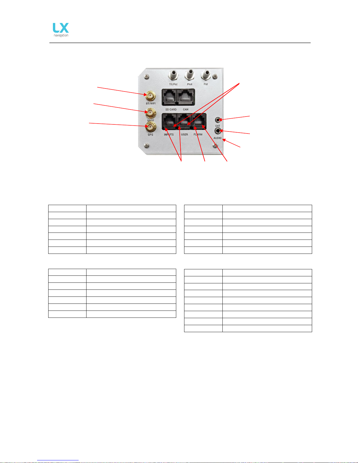
2.3 Electrical installation
Pin out on all connectors:
Pin 1 to pin 6 or 8 (on picture from left to right).
User port (RJ11 – 6pin connector) Flarm port (RJ11 – 6pin connector)
Pin number
Description
1
12 V out
2
Not connected
3
Not connected
4
RS 232 data in
5
RS 232 data out
6
GND
INPUT (RJ11 – 6pin connector) CAN port (RJ45 – 8pin connector)
Pin number
Description
1
Input 1
2
Input 2
3
Input 3
4
Input 4
5
Input 5
6
Common ground (GND)
SD card port (RJ11 – 6pin connector)
Not in use, use the microSD card slot on the front panel.
GPS antenna
Connect the external GPS antenna to this connector. The Era must have this external antenna connected all
the time, otherwise the internal flight recorder will not work.
Wi-Fi/Bluetooth antenna
Connect the external Wi-Fi/Bluetooth antenna to this connector. The Era must have an external antenna
connected all the time, otherwise Wi-Fi/Bluetooth will have no range.
SPOT antenna
The SPOT module (which is offered as an option) requires an antenna connection in order to work.
Pin number
Description
1
12 V out
2
Not used
3
GND 4 RS 232 data in
5
RS 232 data out
6
GND
Pin number
Description
1
12 V
2
12 V
3
12 V
4
CAN_L
5
CAN_H
6
GND 7 GND 8 GND
BT/WIFI Antenna
SPOT antenna
Pin 1
Audio output
(3.5 mm jack)
OAT input
(2.5 mm jack)
GPS antenna
Pin 1
Pin 6
Main power
Pin 6
Page 11
Document Name:
LX Era 57/80 user’s manual
Version: 0.9H
Page 10 of 52
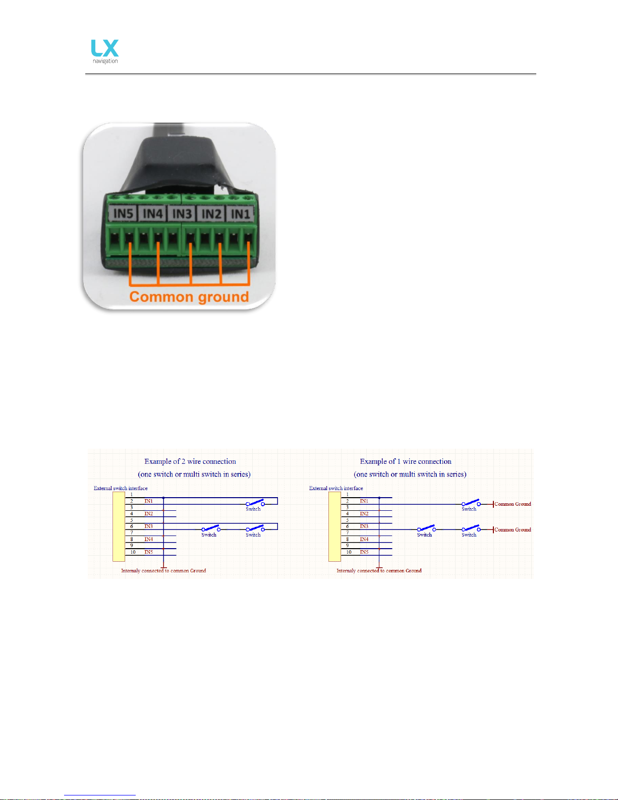
2.4 External switch installation
Up to five external switches can be connected to LX Era. To
connect an external switch to LX Era you have to use the
external switch interface board (included in package).
Every slot available has a signal input and ground input.
The configuration of inputs can be set under Setup ->
Inputs.
User can use two different connection styles:
- 2 wire connection: Connect switch signal and ground
wires to interface board.
- 1 wire connection: Connect switch ground wire to glider
common ground and connect switch signal wire to
interface.
Be careful not to connect signal wire to common ground
input (see picture showing common ground inputs)
The common ground is connected to the glider common
ground via power supply cable (GND).
All inputs except SC will be “active” when the switch is closed (i.e.: signal and ground are in short circuit). If
“Inv” (Invert) is checked on input setting then “active” means when the switch is open.
Example: airbrake warning will be active when switch is not closed and Era is in flight mode. Warning will
disappear when switch is closed.
SC input has its own setting under Vario/SC menu and can be set to be active on when selected to “on”,
“off” or “toggle”.
Example of both connections (1 and 2 wire)
Page 12
Document Name:
LX Era 57/80 user’s manual
Version: 0.9H
Page 11 of 52
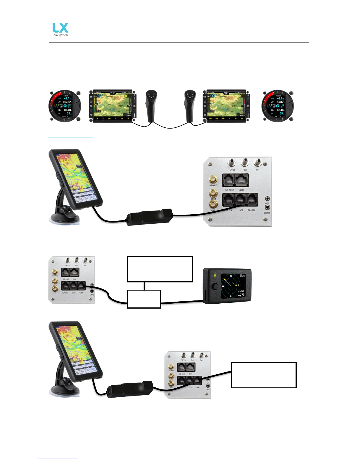
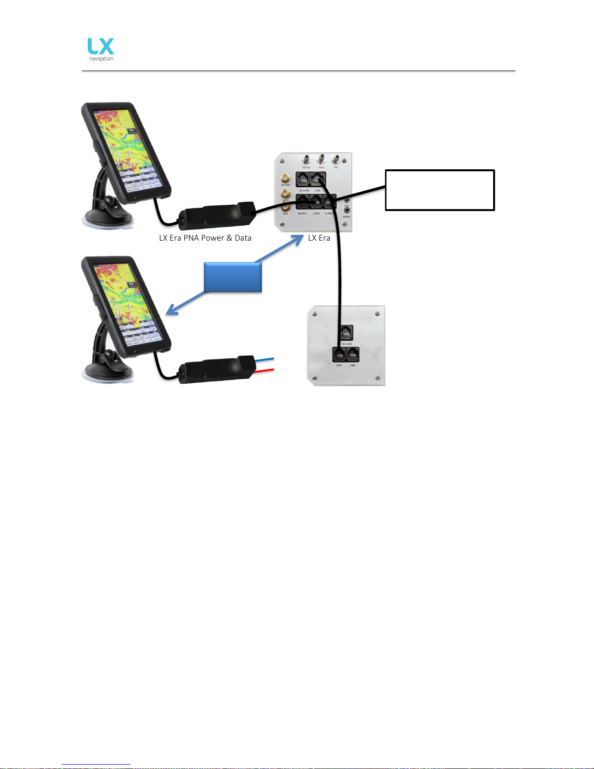
2.5 Installation options
LX Era is compatible with all LX CAN based devices (LX Zeus, LX Joy, LX Era Repeater, CAN Compass, AHRS,
and others). LX Era has an integrated CAN terminator so no other terminator should be used. Only one CAN
terminator should be used (be careful when using LX Era with LX Zeus). (if in doubt please ask your dealer)
Configurations
LX Era – OUDIE
OUDIE LX Era PNA Power & Data LX Era
LX Era – Flarm
LX Era 1:1 1:1 Flarm Colour Display II (optional)
LX Era – Flarm – OUDIE
OUDIE LX Era PNA Power & Data LX Era
LX Flarm
Flarm / RedBox
MiniBox / Flarm Mobile
FlarmMouse
1:1
1:1
Flarm / RedBox
MiniBox / Flarm Mobile
FlarmMouse
1:1
Page 13
Document Name:
LX Era 57/80 user’s manual
Version: 0.9H
Page 12 of 52
LX Era – Flarm – OUDIE – 2nd seat –2nd OUDIE
OUDIE LX Era PNA Power & Data LX Era
OUDIE LX Oudie Power LX Era Repeater
1:1
Flarm / Eagle /
RedBox
MiniBox / Flarm Mobile
1:1
Bluetooth
connection
Page 14
Document Name:
LX Era 57/80 user’s manual
Version: 0.9H
Page 13 of 52
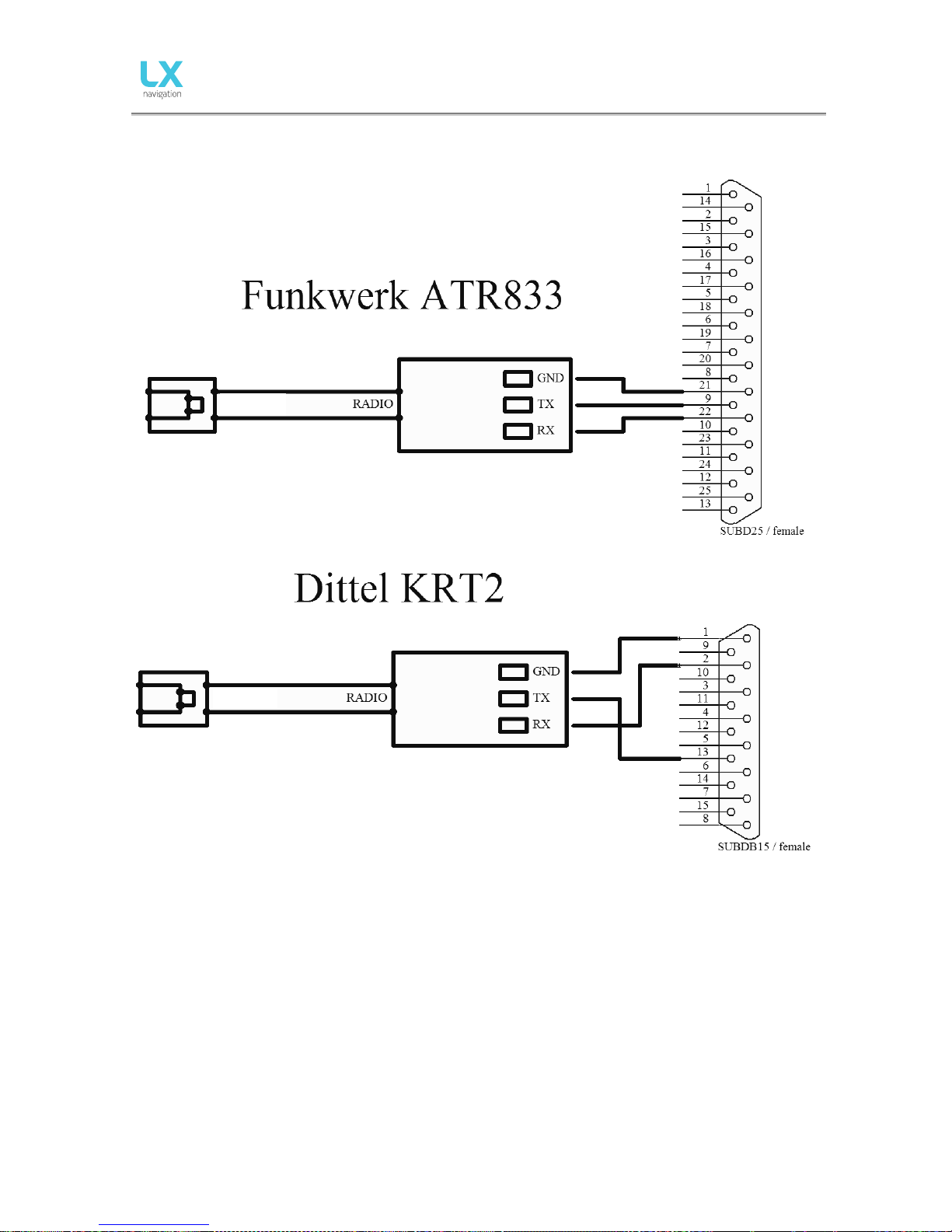
Wirings for radio
ERA
Page 15
Document Name:
LX Era 57/80 user’s manual
Version: 0.9H
Page 14 of 52
2.6 Update procedure
In order to update the device, please follow the steps below:
- Find and download the update file on www.lxnavigation.com
- Send your device’s serial number to update-service@lxnavigation.si and an update code will be sent
to you
- Save the downloaded update file to the supplied microSD card
- Insert the microSD card into the Era
- Turn the device on
- Go to Setup > Transfer > Updates and select the downloaded update file
- Type in the provided password
- Copying of the file, and with it the update process, will commence automatically
- The device will turn off and require another turn on (if it is a standalone version). Zeus versions turn
themselves on automatically)
- ˝LX updating˝ screen will appear
- After the updating process has ended the unit will start itself normally. The user should check if the
correct version is displayed on the greeting screen.
Note!
First update releases (up to version 1.0) do not require an update code, hence all code related steps can be
ignored. When prompted for the update password, simple type in 00000.
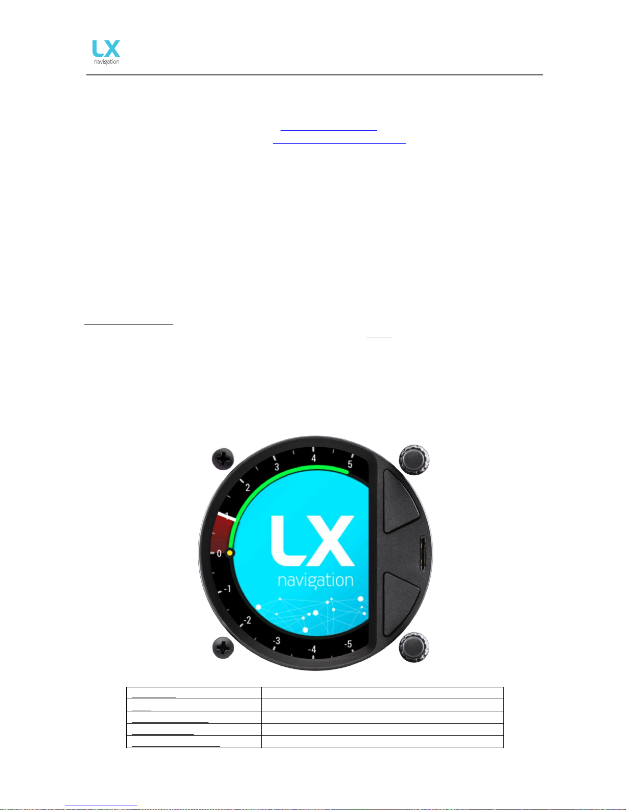
2.7 Technical specifications
The picture below represents the Era with all of its main components. A large 3.5-inch (for the Era 80) or 2.5inch (for the Era 57) transflective LCD display shows all flight-relevant information to the pilot. The Era boasts
a digital needle, which clearly shows current lift, SpeedToFly or other flight parameter.
Two push/rotary knobs and two push buttons are used for all pilot to Era communication.
Dimensions
82 mm x 82 mm x 63 mm
Mass
290 grams
Input Voltage Range
9.0 – 18.0V DC
Average Current
150 milliamps @ 12V DC
Wi-Fi / Bluetooth range
100 metres / 20 metres
Page 16
Document Name:
LX Era 57/80 user’s manual
Version: 0.9H
Page 15 of 52
PART THREE – INTERFACE
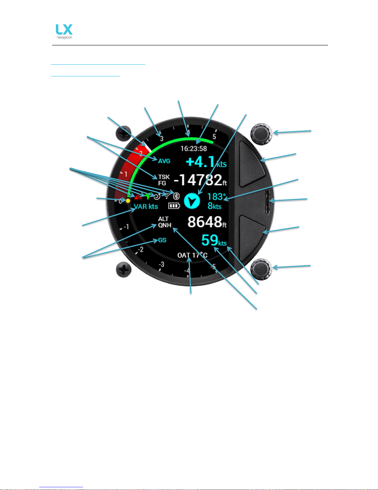
Front panel interface
Below is a representation of the main page
The Era features 6 status indicators described below in their respective order:
- Flarm indicator – appears only when a Flarm device is connected to the Flarm port and
communicating with the Era
- Bluetooth indicator – appears only when a Bluetooth device is connected and communicating with
the Era
- Wi-Fi indicator – appears only when a Wi-Fi device is connected and communicating with the Era
- GPS indicator – is always displayed, a green arrow indicates good GPS signal, and a red one indicates
bad GPS signal
- Circling/SC mode indicator – indicates whether Era is in Speed Command (SC) or Vario mode
- Battery status indicator – shows the current state of the glider`s battery. White battery outline
indicates it is using the glider`s battery. A red battery outline indicates it is using its built-in battery
UTC
time
Indicators
(1~2)
Digital
Digital
needle
MacCready
value
SpeedToFly
Wind direction (in
regards to plane)
Wind speed
and direction
MicroSD card
reader
Indicator value
Indicator unit
Status
indicators
Outside Air
Temperature
Mode
Indicator name
Indicators
(3~4)
Upper
rotary/push
knob
Upper push
button
Lower push
button
Lower
rotary/push
knob
Page 17

Document Name:
LX Era 57/80 user’s manual
Version: 0.9H
Page 16 of 52
Use of rotary switches
To move around and access all functions of the unit, two rotary knobs with push buttons are used.
The upper push/rotary knob serves the function of Cancel and from now on will be referred to as ‘’Cancel’’.
Pressing the upper push/rotary knob will exit from a menu and cancel the settings. Turning the rotary knob
in most pages will change the volume.
In situations when you are choosing a value (e.g. QNH and altitude in the initial setup) it will change the
value by 10-fold.
The lower push/rotary knob serves the function of Enter and from now on will be referred to as ‘’Enter’’.
Pressing the lower push/rotary knob will enter a menu, or enter a value, or open a hidden menu.
Turning the rotary knob will swipe through pages, menus, or change values by 1, depending on the situation.
To change the value of a parameter, enter must be pressed to activate the rotary keyboard (appears on the
left).
Use the lower rotary knob to input the desired value and confirm it by pressing enter.
To exit edit mode, fill out all of the fields (when a number is in question) or simply choose the enter sign (↵).
For quick change (multiplication by 10 steps) press enter button and while holding it pressed, rotate the
rotary switch.
The upper push knob is used for zooming in on all navigation pages. When choosing a value, it will behave
the same as the upper push/rotary knob – it will increase the value by 10-fold.
The lower push knob is used for zooming out on all navigation pages. When choosing a value, it will behave
the same as the upper push/rotary knob – it will decrease the value by 10-fold.
A red cross across a page is a standard aviation notification, which indicates
that this page is either not available or not working for some reason. On
navigational pages, it is usually due to bad GPS connection and on AHRS page,
it is indicating that you do not have an AHRS unit connected to your Era.
Connecting the missing module or antenna, or allowing the antenna to get a
GPS connection will eliminate this symbol. Pages that are not used can be
hided, as explained in section 4.11.12.
Page 18

Document Name:
LX Era 57/80 user’s manual
Version: 0.9H
Page 17 of 52
To exit from any subpage or list, a pilot has 3 options:
- Select “Exit” option which is always located at the end of each page / list
- Move to the top of each page / list where a blue circle with a black backward arrow is located (←).
Exit option is highlighted, when this circle becomes filled with blue.
- Press the upper push/rotary knob
Exit at the bottom.
Exit at the top.
Value can’t be changed (grey lettering).
Value can be changed (white lettering).
Grey rectangle indicates the character which is being
edited. Edit character with rotary switch.
Page 19

Document Name:
LX Era 57/80 user’s manual
Version: 0.9H
Page 18 of 52
PART FOUR – SOFTWARE
4 Main pages
Initial setup
After power on the Initial setup appears. This screen is used to input basic information which can often
change daily
- Select pilot (offers the selection of different user created pilot profiles)
- Set elevation (set the elevation of your current location)
- Set QNH (set the current QNH pressure)
If used in LX Zeus configuration, all these settings are done on LX Zeus and this screen is not visible on LX
Era.
All information is provided by turning the push/rotary knob. By pressing enter, the current value is selected
and the next parameter is shown.
Structure of main pages
To switch between main pages use left/right rotation of the lower rotary switch. The complete structure of
the main pages can be seen in the figure below.
Vario - main page
Thermal assistant page
Flarm radar page
Page 20

Document Name:
LX Era 57/80 user’s manual
Version: 0.9H
Page 19 of 52
TP navigation page
APT navigation page
TSK navigation page
G – force page
AHRS page **
GPS info page
* When used as a part of an Era
– Zeus system, not all options are
present.
** Only when AHRS module is
detected on CAN bus.
Logbook page
Setup page*
Page 21

Document Name:
LX Era 57/80 user’s manual
Version: 0.9H
Page 20 of 52
4.1 Vario page
The Vario page is used for displaying a wide spectrum of flight-relevant information.
There are four indicator fields available on the vario page when in thermal mode,
and another when in SC mode. Two are above the middle row and two below.
All of them (apart from the middle row) can be set to user preferences.
In the middle row, different status icons are shown:
- Main battery indicator (outline of symbol is white):
3 green bars – more than 12.0V
2 yellow bars – more than 10.8V
1 red bar – less than 10.8V
- Backup battery indicator (outline of symbol is red):
3 green bars – more than 80% left
2 yellow bars – between 20% and 80% left
1 red bar – less than 20% left
- SC/Thermal icon:
Straight arrow – SC mode
Spiral arrow – thermal mode
- GPS status:
Green arrow – GPS ok (3D)
Red arrow – GPS bad
- Bluetooth icon:
Is visible when Bluetooth connection is active
- Flarm icon:
Is visible when Flarm is detected on the system
- Green arc is the SC bar which will move according to the MacCready
setting, IAS and movement of the airmass around the glider
- Wind is shown with three parameters:
o Wind arrow shows wind direction relative to the glider
o The upper number (on the right side of the wind arrow) shows the
wind direction
o Below the wind direction the wind speed is shown with the units
displayed beside it
- Below the GPS signal indicator, one of the following is shown, informing the
pilot what is the digital needle currently indicating:
o VAR – vario
o NET – Netto
o SC – Speed command
o REL – Relative
o G - Force
Pressing enter whilst
on the Vario page will
open a quick input
window, allowing the
pilot to quickly
change Volume,
MacCready, Ballast,
Bugs, QNH pressure
and brightness level.
Page 22

Document Name:
LX Era 57/80 user’s manual
Version: 0.9H
Page 21 of 52
Configuration with LX Joy:
When an LX Joy is connected to an LX Era in standalone configuration, up/down keys can be used to change
the volume with left/right controls used for scrolling through the pages. Pushing the centre button on the LX
Joy opens a pop up window, used for entering Volume, MacCready, Ballast, Bugs and QNH.
4.2 Thermal assistant page
The thermal assistant page is used to help the pilot better understand the
current thermal. The thermal itself is represented with dots of different sizes
and colours.
Default colour scheme:
White coloured dots show maximum climb detected in last turn.
Dot thickness represents strength of climb/sink.
Red dots represent climb.
Blue dots represent sink.
MC colour scheme:
White coloured dots show maximum climb detected in last turn.
Dot thickness represents strength of climb.
Red dots represent climb which is stronger than 1.2*MC setting.
Yellow dots represent climb in range of 0.8*MC and 1.2*MC setting.
Blue dots represent climb less than 0.8*MC setting.
If MC setting is less than 0.5m/s (1kt), default colour scheme is used!
In the middle of the TA circle, wind is shown as a blue arrow with numerical
indication for direction and speed. Wind arrow is orientated track up.
Other marks on this page:
- T AVG: Average of thermal from start of circling until “now”
- AVG: Integrator value of vario
- MAX: Maximum value in thermal – white dot
- GAIN: Altitude gain from start of circling until “now”
To access TA setup, press enter on this page.
Auto TA: It is possible to enable automatic switch to thermal assistant from any
other page when circling is detected.
Max. beep: Position of max thermal (white dot) can be reported as a beep. If
thermal beep is enabled, LX Era will generate beep always when you are at the
position of maximum climb (white dot).
Beep offset: Maximum thermal is announced with beep sound if max beep is enabled. Set beep offset in
seconds here. Beep will be generated before you reach maximum thermal.
Page 23

Document Name:
LX Era 57/80 user’s manual
Version: 0.9H
Page 22 of 52
4.3 Flarm radar page
The graphic display is divided into 2 or 3 circles (depends on zoom setting). The
outer circle represents zoom distance. The blue glider symbol is always
positioned in the middle of the screen
Near gliders are displayed as yellow. All gliders located in radio range will be
shown simultaneously on the display.
ADSB objects that have been detected will be shown as green triangles with the
triangle, pointing in the direction the object is tracking.
Non-directional objects are represented as red circles about the centre of the
screen. The size of the circle represents the relative distance to that target. No
bearing to the target is provided.
Current zoom is displayed in the top part of the largest circle. Relative altitude
and current vario of a selected Flarm object is shown in yellow, next to the object
itself.
The graphic display orientation is always track up. To improve orientation, N, E, W
and S are added to the display.
Note!
Gliders presented as a dot on the screen, are gliders where pilots have
intentionally activated the PRIVACY mode on their Flarm unit. Gliders in privacy
mode send limited data strings and can’t be visualized completely. However, all
warnings will appear regardless of privacy mode.
To access Flarm radar options, press enter on this page.
Configuration with LX Joy:
When LX Joy is connected to LX Era standalone configuration, up/down keys will change zoom settings on
Flarm radar page. Pushing the centre button on the LX Joy opens a new page, used for setting Zoom level
and selecting a Flarm object. Please note that volume can’t be set on this page.
Flarm select
To select a new Flarm object, press enter on the Flarm radar page and use the
“Select” option. An opaque yellow circle will be visible around the selected Flarm
object, indicating that you are in selection mode.
Use the rotary switch to select new Flarm object.
Pressing enter will finish the selection operation and return the display to the
Flarm radar page.
Page 24

Document Name:
LX Era 57/80 user’s manual
Version: 0.9H
Page 23 of 52
Flarm warning
When a Flarm warning is detected, Era will show a Flarm warning page with
direction to the target provided by the red radar arcs, an above/below indication
on the left of the screen, numerical information for horizontal distance at the top
of the screen and relative altitude at the bottom of the screen.
Flarm warning setting:
- enabled, this page will override any Era menu / page
- disabled, then this page will be seen only on Flarm radar page
4.4 TP navigation page
In order to use this page to its maximum extent, the user should first import turnpoint, and airfield files. For
more information on this subject, please refer to Setup/SD Card/Load TP. If LX Era is used in LX Zeus
configuration, TP database selected under TP/Task/Era list on LX Zeus is automatically transferred (unlimited
number of TP’s). TP is displayed as a white dot with a ‘’W’’ written inside (Waypoint). Navigation is always
“track up”.
On the top of this page the name of the selected turnpoint is written. On the
bottom side of the screen, Final glide (FG), Bearing (BG), Track (TRK) and Distance
(DIST) to the selected point are written.
Below the TP name, a steering symbol will inform the pilot how many degrees (°)
does he needs to correct his track by in order to fly towards the selected
turnpoint.
In the left part of the screen, standard wind information can be read.
The Arrow shows the wind direction relative to the glider, its direction relative to
North; the speed is shown below.
Pressing the enter button whilst on TP page will open a TP settings menu. This
menu can be used for selecting the desired point.
The desired point can be chosen either by scrolling to it, or by using a filter. Three
different filters are available for narrowing down your search: Name, Code and
Distance. After confirming the desired filter, a filtered list will appear.
These options are valid only when used without a Zeus. Otherwise, Zeus’
turnpoint selection should be used.
Selected point is saved after a power reset.
Configuration with LX Joy:
When an LX Joy is connected to an LX Era in standalone configuration, up/down
keys will change zoom settings on TP page and left/right will sweep between
pages. Pushing the centre button will act as Enter.
Page 25

Document Name:
LX Era 57/80 user’s manual
Version: 0.9H
Page 24 of 52
4.5 Airport navigation page
In order to use this page to its maximum extent, the user should first import airspace and airfield files. For
more information on this subject, please refer to Setup/SD Card/Load TP. If LX Era is used in LX Zeus
configuration, APT database selected under TP/Task/Era list on LX Zeus will be automatically (unlimited
number of APT’s). TP is displayed as a white dot with a ‘’W’’ written inside (Waypoint). Navigation is always
“track up”.
On the top of this page the name of the selected airport is written. On the
bottom side of the screen, Final glide (FG), Bearing (BG), Track (TRK) and
Distance (DIST) to the selected point are written.
Below the ATP name, a steering symbol will inform the pilot how many degrees
(°) are needed to correct track in order to fly towards the selected APT.
In the left part of the screen, standard wind information will be displayed.
The Arrow shows the wind direction relative to the glider, its direction relative
to North, with the wind speed being shown below.
Pressing the enter button whilst on APT page will open an APT settings menu.
This menu can be used for selecting the desired point.
The desired point can be chosen either by scrolling to it, or by using a filter.
Three different filters are available for narrowing down your search: Name,
Code and Distance. After confirming the desired filter, a filtered list will appear.
These options are valid only when used without a Zeus. Otherwise, Zeus’
turnpoint selection should be used.
Selected point will be saved after a power reset.
Configuration with LX Joy:
When an LX Joy is connected to an LX Era in standalone configuration, up/down
keys will change zoom settings on APT page and left/right will sweep between.
Pushing the centre button will act as Enter.
Page 26

Document Name:
LX Era 57/80 user’s manual
Version: 0.9H
Page 25 of 52
4.6 Task navigation page
This page should be used for navigation when flying tasks.
There are two ways of entering a task. Either by selecting a. CUP file, which contains a task inside, or by
creating it by hand.
For more information on how to import TPs please refer to section Setup/SD Card/Load TP. Navigated task
TP is displayed as observation zone and a white line from zone to the glider shows the direction in which the
pilot should fly. A white line from centre of observation zone will show next leg of task. Navigation is always
“track up”.
Configuration with LX Joy:
When an LX Joy is connected to an LX Era in standalone configuration, up/down
keys will change zoom settings on TSK page and left/right scrolls between pages.
Pushing the centre button acts as Enter and opens TSK Setup.
On the top of this page pilot can find the name of navigated TSK turnpoint. On
the bottom part of the page, navboxes show final glide (FG), bearing (BRG),
track (TRK) and distance (DIST) to the navigated point.
Under the TSK name, steering symbol information will inform the pilot how
many degrees (°) he needs to correct his track by in order to fly directly to the
selected turnpoint.
In the left part of the screen, standard wind information is displayed.
The Arrow shows the wind direction relative to the glider, its direction relative
to North, with the wind speed being shown below.
Pressing enter, “TSK SETUP” will be activated allowing a task to be created or
edited. Additional TP’s can be added, removed, zones changed etc.
Additional options are offered to the pilot only in standalone configuration or
in backup mode. In LX Zeus configuration, TSK TP options can be set on LX
Zeus, and LX Era will receive task information from the Zeus.
Additional options:
- Go to: Navigate to that point on task
- Select turnpoint
- Select airport
- Insert turnpoint
- Insert airport
- Edit zone
- Delete
Page 27

Document Name:
LX Era 57/80 user’s manual
Version: 0.9H
Page 26 of 52
Observation zone
If auto next option is enabled, next TP will be selected automatically when pilot reaches TP zone.
User can change A1, R1, A2, R2, zone type, A21 and auto next option.
4.7 G-Force page
The G-force page consists of a circular scale representing the different values of
acceleration and a yellow dot that moves in accordance with the current force
resultant. Located at the bottom of the display, the maximum and minimum Gforce experienced are shown. The current G-force is shown at the top of the
page. These values can be cleared anytime during the flight in the G-FORCE menu.
The Range setting is shown by the small text in the circular scale. This range can
also be set in the G-FORCE menu.
To enter G-FORCE menu, press enter on G-force page.
Configuration with LX Joy:
When LX Joy is connected to LX Era standalone configuration, up/down keys will
change range settings on G-force page. Pushing the centre button on the LX Joy
opens a new page, used for setting range level.
Please note that volume can’t be set on this page.
Page 28

Document Name:
LX Era 57/80 user’s manual
Version: 0.9H
Page 27 of 52
4.8 GPS info page
Basic GPS information is shown here.
- Status: 3D/6 – 3D GPS, 6 satellites found
- Status: Last fix – currently no satellites are found, last known
location is displayed as Lat, Lon
- Lat: N or S – latitude, North or South
- Lon: W or E – longitude, West or East
- Time: only UTC time
- Date: current date
4.9 Logbook / statistic page
Logbook
On the ground (flight recorder is not running) the logbook can be accessed by
pressing enter on the logbook page.
Pilot can copy take-off / landing time to personal logbook and transfer flight to
external SD card for OLC upload.
The last 50 flights are listed. Any older flights will be erased from the logbook list.
Press enter on selected flight to open the flight info, where “copy” option is
available to transfer flight to external SD card.
Flight is copied to external SD card into LX/FLIGHT folder
After the flight has been transferred, “Copy OK” will be displayed. Press enter to
continue.
In LX Zeus configuration, flight can be downloaded from LX Zeus logbook page to
the LX Zeus USB key.
Page 29

Document Name:
LX Era 57/80 user’s manual
Version: 0.9H
Page 28 of 52
4.10 Statistics
During flight, statistics of the flight are shown on this page. Take-off time is
shown at the bottom of the page and flight duration at the top. A barograph
line shows flight altitude for the last hour.
Pressing enter on this page will offer the pilot an option to end flight
immediately on demand.
If “Yes” option is selected, message “Calculating security” will be visible.
Selecting “No” will do nothing and statistics page will be visible again.
After the pilot has landed the flight recorder will start a 5-minute countdown
after which the before the flight will be finished automatically. The finish
flight page will be shown automatically after 10 second of countdown to alert
the pilot that flight will end in 5 minutes. The pilot can either wait until the 5minute countdown is complete or press enter to end the flight immediately.
Page 30

Document Name:
LX Era 57/80 user’s manual
Version: 0.9H
Page 29 of 52
4.11 Setup
Under setup, the pilot can set all parameters of the unit. Setup page can be accessed only if LX Era is used as
a standalone unit. When connected to LX Zeus, all information is automatically synchronised between LX
Zeus and LX Era. In the case of backup operation with LX Zeus, Setup will appear automatically.
Pilot
All entered data (except for weight), will be written to the .igc log file as pilot
declaration info.
Pilot can either select pilot that is already saved in the database or select
“EMPTY” to create a new pilot. If a pilot is already saved, name initial and
surname are shown. Pilot name or “EMPTY” is automatically shown in the second
line. Code input will be required if selected user has his profile protected with
user code.
- Pilot name: edit the name of the pilot.
- Pilot surname: edit the surname of the pilot.
Pilot’s weight is added to the whole weight of the glider to calculate actual wing
loading.
- Weight: edit the weight of the pilot.
- Co-pilot’s data is visible in-flight declaration (IGC file).
- Copilot name: edit the name of copilot.
- Copilot surname: edit the surname of copilot.
Co-pilot’s weight is added to the whole weight of the glider.
- Copilot weight: edit the weight of copilot.
Pilot should set the actual QNH and elevation of the take-off airport on the initial
setup screen. If the QNH changes during flight the pilot can change the altitude
calculation for the final glide. If has changed since take-off, and no min-flight
correction is made, the final glide altitude will not be corrected and will still be
the same as set on the initial setup.
Reserve is the safety arrival altitude that is added to the required final glide
altitude so that the glider arrives over the destination at the selected reserved
altitude (AGL).
Page 31

Document Name:
LX Era 57/80 user’s manual
Version: 0.9H
Page 30 of 52
Vario/SC
In this menu pilot can set vario settings:
- Altitude sensor allows the user to choose which sensor will provide
altitude information to the instrument. At lower altitudes, the
pressure sensor is more accurate and effective. At very high altitudes,
measurement error rises because of the nature of the pressure
sensor. For such high altitudes, the IGC (GPS) sensor is recommended.
- Zero frequency is a frequency generated at 0 m/s (0 kts)
- Positive frequency is the frequency at maximum climb shown on the
scale (depends on range setting)
- Negative frequency is the frequency at maximum sink shown on the
scale (depends on range setting)
- Audio test will generate vario movement from +6m/s to -6m/s (+-12
kts) so user can check audio setting in this range
- Range is the scale for the vario. Three options are available – 2.5, 5
and 10 m/s (5, 10 and 20 kts, according to user selected units).
- Filter defines the dynamics of the vario needle and sound. The smaller
the time the faster is the response and vice versa
- TE Level – look for the explanation below
- Integration time defines integration period for averaging the vario data
in seconds
- SC mode allows the pilot to choose between different methods for
automatic switching, or manual SC switch
- SC switch mode for different types of switches
- SC speed can be set and should be set only when ˝Speed˝ has been
chosen under ˝SC mode˝
- SC silence mutes the range around 0 – for instance, 1.5m/s means that
all values from -1.5m/s to +1.5m/s (+-3 kts) will be muted.
TE Level is the level of electronic TE (total energy) compensation for the
variometer. Selection of the electronic compensation method is done by
selection of TE level. 0% means total energy compensation using a TE probe.
After an input of a percentage, which is more than zero, the special software
routines will be activated and will provide an electronic compensation process.
Page 32

Document Name:
LX Era 57/80 user’s manual
Version: 0.9H
Page 31 of 52
TE compensation can be fine-tuned during flight with the following procedure. It is essential that this is only
done in smooth air; it is not possible to tune the TE accurately when there is thermal activity.
- Select 100 % TE level.
- Accelerate up to approximately 160 km/h (75 kts) and keep the speed stable for a few seconds.
- Gently reduce the speed to 80 km/h (45 kts).
Observe the vario indicator during the maneuver. At 160 km/h (75 Knots) the vario will indicate about –2
m/s (-4kts). During the speed reduction, the vario should move towards zero and should never exceed zero
(slightly positive indications are acceptable). If the vario shows a climb, then the compensation is too low,
increase the TE level; and vice versa. Repeat this procedure and make further adjustments if necessary.
SC mode:
- Manual: pilot will activate the SC mode with push of an external button. Settings for the SC button
can be set under SC Switch option.
- Speed: SC mode will be automatically activated when the “SC speed” is exceeded.
- Circling: SC mode will be automatically activated when LX Era detects that you have left a thermal,
and will automatically switch back to vario mode when you enter next thermal.
With the use of external switch, it is possible to switch between SC and vario manually, if manual SC mode is
selected.
- SC Switch:
• ON means that closing of the switch will cause SC mode.
• OFF means that closing the switch will select vario mode.
• Toggle each press of the button will change between SC and vario mode.
- SC Speed setting is the speed value at which the SC Mode is activated if SC mode is set to speed.
- SC Silence defines no audio area around zero in SC mode.
Polar
Nearly all glider polars are stored in the LX Era memory. It is also
possible to create a user defined polar.
Grey fields may not be edited
It is always possible to edit empty weight of the glider.
To create custom polars find “USER” in first line. When “USER” is
selected all polar data will turn to white so the pilot can edit them.
Reference mass is to be used only with user defined polars.
The reference mass represents the mass, at which the input polar
parameters are based.
Page 33

Document Name:
LX Era 57/80 user’s manual
Version: 0.9H
Page 32 of 52
Units
The units menu holds the units options for all flight parameters, shown as either an indicator, navbox,
widget or digital needle.
Pilot can set units for:
- Vario (m/s, kts)
- Altitude (m, ft)
- Distance (km, nm, mi)
- Speed (km/h, mph, kts)
- Wind (km/h, mph, kts, m/s)
- Pressure (mbar, inHg)
- Temperature (°C, °F)
- Weight (kg, lb)
- Area (m
2
, ft2)
Page 34

Document Name:
LX Era 57/80 user’s manual
Version: 0.9H
Page 33 of 52
Indicators
Pilot can select needle functions in vario and SC mode.
- Vario: vertical speed of the glider
- SC:
• needle on 0, optimum flying condition (MC)
• needle is above 0, slow down
• needle is below 0, speed up
- Netto: Shows air mass vertical movement at that moment
- Relative: Shows vario if pilot were to start circling at that point
- G-force: Shows current G-force
Vario/SC lower 2 represents the lower most numerical display indication in
Vario/SC mode on vario page. Vario/SC lower 1 represents the one above
Vario/SC lower 2.
In all cases the pilot can choose from:
- Empty: Leaves the indicator window empty
- Vario Avg.: Average vario value in a specific window (chosen when
setting Integration time)
- Time: UTC time
- Flight time
- Leg time: When connected to Zeus it shows actual TSK leg time
- Altitude: Altitude according to QNH data inserted
- Distance: When connected to Zeus it shows distance on active page
(APT, TP or TSK)
- Distance TP: Distance to turn point selected on TP page
- Distance TSK: Distance to next turn point selected on TSK page
- FG: When connected to Zeus it shows final glide on active page (APT,
TP or TSK)
- FG TP: Final glide to turn point selected on TP page
- FG TSK: Final glide to next turn point selected on TSK page
- TAS: True Air Speed
- IAS: Indicated Air Speed
- Alt. QNH-ft: QNH altitude in feet
- Flight level
- OAT: Outside Air Temperature
- Vario netto: Netto variometer
- Vario relative: Relative variometer
- IGC Altitude
- SpeedToFly: Speed to fly at given MC setting and air mass around the
glider
- G-force: Current force resultant
- Flap: Shows the current flap position
- Rec. Flap: Shows recommended flap position
- TRK: Current Track
- Ground speed
- Distance APT: Distance to chosen APT
- FG APT: Final glide on chosen APT
Page 35

Document Name:
LX Era 57/80 user’s manual
Version: 0.9H
Page 34 of 52
Logger
Warnings
Warnings are used to inform the pilot that some flight related data is outside margins. When warning state
is detected by LX Era, the pilot will get a red warning message box with description of what is outside
margins.
Pilot can enable (box is checked) audio warnings and Flarm warnings.
- Audio: if disabled, voice warning will not be generated – only visual warning
message box
- Inputs: Must be turned on to enable input port warnings such as airbrakes,
gear etc.
- Altitude warning: warning when flying over selected altitude
- Stall: warning when the glider speed is lower than stall speed
Flarm: Flarm warning page will be seen only on Flarm radar page if this option is
disabled, otherwise it will override any Era page/menu when warning is detected.
Vne: warning when speed exceeds Vne speed
The pilot can set recording interval, registration number of the glider, competition
ID, competition class and event settings.
Input data is then shown as declaration in every IGC flight file.
Set number of event fixes and event record interval.
Event can only be activated when in flight mode, either by going to GPS info page
and pressing enter, or using inputs.
Page 36

Document Name:
LX Era 57/80 user’s manual
Version: 0.9H
Page 35 of 52
Voice
Pilot can set the voice volume of the device and mixer settings. The percentage
of mixer means how much voice is mixed with vario beep. Low percentage
means lower voice to vario beep ratio and higher percentage means higher
voice to vario beep ratio.
Enabling Flarm traffic option will generate voice announcement when new
Flarm object is detected.
Enabling Flarm warning option will generate voice warning when Flarm
collision warning is detected.
Enabling Flarm obstacle option will generate voice warning when obstacle from
Flarm database is detected in front of the glider.
With Flarm h. distance setting, user can enable/disable horizontal voice
information for Flarm traffic.
With Flarm v. distance setting, user can enable/disable vertical voice
information for Flarm traffic.
Page 37

Document Name:
LX Era 57/80 user’s manual
Version: 0.9H
Page 36 of 52
Transfer
The transfer page is used for transferring turnpoint and task files (.cup), airport
files (.af), airspace files (.cub) and software updates (.lxu).
It is also used for selecting active files and deleting old files.
Turnpoints
After selecting “Turnpoints” option, multiple options are shown:
- Load is used for uploading files from microSD to device
- Delete is used for erasing files from the device
- Select is used for selecting the active file
- Deselect is used for deselecting the file
A list of .cup files (up to 20) found in the root of external microSD card will be
listed under Load Turnpoint.
Select file from which you wish to import TPs and tasks to internal database.
After importing, the process can take from 5 sec. up to 10 min (depends of TP
number and alphabetical sort inside CUP file). Number of TPs is not limited but
we recommend to use CUP file with up to 6000 points. Name of every TP will
be shortened to max 11 characters after import.
Page 38

Document Name:
LX Era 57/80 user’s manual
Version: 0.9H
Page 37 of 52
Load TSK
After selecting “Load TSK” option, list of all CUP files (up to 20) found on external
SD card in LX/TP folder will be listed here.
Select file from which you wish to import TSK to internal memory.
After selecting file from which you wish to import task, the first 20 tasks found in
the file will be listed. Select the task you wish to import and press enter.
Observation zones will be loaded as well if defined in file, otherwise standard FAI
zones be used.
Warning: Due to internal task limitations, only first 18 points of selected task will be
loaded from a file.
Wait until load is finished.
Airports
After selecting “Airports” option, multiple options are shown:
- Load is used for uploading files from microSD to device
- Delete is used for erasing files from the device
- Select is used for selecting the active file
- Deselect is used for deselecting the file
A list of all .af files (up to 20) found in the root of external microSD card will be
listed under Load Airports.
Select the file from which you wish to import APTs to internal database.
.af file is commonly used file for transferring APTs.
Page 39

Document Name:
LX Era 57/80 user’s manual
Version: 0.9H
Page 38 of 52
Airspace
A list of all .cub files (up to 20) found in the root of external microSD card will be
listed under Load Airspace.
Select the file from which you wish to import Airspace data to internal database.
.cub file is commonly used file for transferring Airspace data.
Software update
Before update, the user should request update code at: updateservice@lxnavigation.si . In the email request, the user should provide serial
number of the unit and version to which he wishes to update.
User should copy the new version to the root of external microSD card, then
insert it into the LX Era and use “Software update” option to update the unit to
the new software version. After selecting “Software update”, list of all version
(*.lxu) files will be shown. Pilot should select the version he wishes to load.
For the first versions (below 1.0) the update code is commonly 00000.
After code is entered the update procedure will start. LX Era will report an error
if the code is not correct. Update can take up to 4 min. Device will automatically
restart after a successful update. LX Era will also update all LX CAN devices
connected to the system.
Flarm NET it is possible to import Flarm NET database for Flarm objects.
Page 40

Document Name:
LX Era 57/80 user’s manual
Version: 0.9H
Page 39 of 52
Inputs
LX Era has a possibility of five different user defined inputs. Each input can be set
accordingly. There are seven options to choose from:
- None: nothing is connected to the input
- SC: the device changes mode from vario to SC mode
- VP: (vario priority) the device goes to vario mode no matter what SC mode is
selected
- Event: event in flight recorder is activated and pilot gets a message shown
on display
- Gear: If enabled under warnings will generate gear up/down warnings after
take-off / before landing
- Airbrakes: if enabled under warnings, will generate airbrakes warning if they
are opened during take-off
- Ballast: not yet supported
Inv – invert mode:
Each input has invert option. When invert option is enabled, it will “invert” active
state of this input.
Invert option:
- off: input is active when switch is closed
- on: input is active when switch is opened
If two or more inputs are the same, the corresponding action will be made when
all of them are active (active = switch closed or switch open in Inv mode!).
Please refer to external switch installation section to see how to connect to
external switch interface
Functions of inputs:
- SC: LX Era supports two modes of operation: Vario and SC. With SC input,
the user can change between these two modes.
- VP: Vario priority is used when user wants to have vario mode active. VP
input has higher priority than SC input!
- Event: To trigger pilot event in logger with higher recording interval, this
option of input should be selected.
- Gear: If any gear is selected, gear warning will be announced as follows:
- gear is out is detected 10min after take-off and height is more than 500m
above take-off location.
- gear is not out and altitude is less than 200m in 5km circle of take-off
position and flight time is more than 5min.
- on out landing (if airbrakes are out, elevation less than 600m QFE (1900ft),
distance from take-off more than 5km) and gear is not out.
Airbrakes:
If any airbrake is selected, gear warning will be announced as follows:
- airbrake is out during first 10min of flight (take-off / aero tow time).
Page 41

Document Name:
LX Era 57/80 user’s manual
Version: 0.9H
Page 40 of 52
NMEA
This setup page is used to set the data to be sent to a third-party unit connected
through BT or user port.
The pilot can set baud rate for communication through User port or Flarm port.
Pilot can select from: BR4800, BR9600, BR19200, BR38400, BR57600 and
BR115200 options.
LX Era is capable of sending NMEA data to third party units such as PDA or
PNA. The data is available on the connector marked as USER and BT port.
Five data strings are offered.
Selected (checked box) NMEA data will be sent over User port and Bluetooth.
- GPGGA – Global Positioning System 3D-Fix Data
- GPRMC – Recommended Minimum Specific GPS/TRANSIT Data
- GPRMB – TP navigation info
- LXWPx – sentences contain pressure and altitude information in addition to
IAS data
- PFLAx – Flarm traffic info. Data must be enabled, if Flarm data is required on
a PDA
- Radio – Enable this option when radio is connected to user port. Control
over the radio is only possible in conjunction with LX Zeus.
- Transponder – If enabled, baud rate on Flarm port will go to 9600 and GPS
data will be transmitted on Flarm port
- When Radio option is enabled all other outputs on User port are disabled, but
are still present on BT port.
Page 42

Document Name:
LX Era 57/80 user’s manual
Version: 0.9H
Page 41 of 52
Pages
The pilot can select which main pages are active. Page is active when box is
checked. There are eight main pages available:
- Thermal assistant
- Flarm
- TP page (turnpoint)
- APT page (airport)
- TSK page (task)
- G-force
- AHRS (artificial horizon)
- GPS info
Password
To access some options a password is required. Available passwords are:
- 46486: sets LX Era to factory settings.
- 99999: clears all flights from flight recorder – logbook is empty.
- 28346: audio player (will play any wav file 8bit 16kHz mono from root
of external SD card).
- 66666: clears actual task
- 55555: clears internal TP database
Info
LX Era info page with displayed information:
- Serial number
Page 43

Document Name:
LX Era 57/80 user’s manual
Version: 0.9H
Page 42 of 52
- IGC serial number
- Firmware version
- Hardware version
Shutdown
When the shutdown option is selected, this screen will be shown to confirm that
you wish to shutdown the device. Selecting “No” will return you to the setup
menu, while selecting “Yes” will turn off the unit.
If shutdown option is selected during flight, this message will be shown. "Please
finish the flight first and then turn it off!"
Page 44

Document Name:
LX Era 57/80 user’s manual
Version: 0.9H
Page 43 of 52
PART FIVE – CONNECTIVITY
5 Wi-Fi/Bluetooth module
LX Era has an internal Bluetooth 4.0 module which is always on and cannot be turned off. At the back of the
unit, there is an SMA connector for external Wi-Fi/Bluetooth antenna, that enables better range.
5.1 Pairing with PNA and Android devices
Perform a search of BT devices on your PNA/PDA/Android device. LX Era XXXXX, where XXXXX represents the
serial number of the unit, will be visible on the device list, when in range and turned on. Pair code will be
requested to start communication with PDA/PNA/Android device and Lx Era. Enter pair code: 1234
After successful connection, Bluetooth icon will be visible on main vario page.
5.2 Supported data transfers
Description
Supported
Remark
GPGGA
Yes
If enabled in NMEA setting
GPRMC
Yes
If enabled in NMEA setting
GPRMB
Yes
If enabled in NMEA setting
LXWPx (LX data)
Yes
If enabled in NMEA setting
PFLAx (Flarm data)
Yes
If enabled in NMEA setting and Flarm is connected to Lx Era
Declaration from Era
No Declaration to Era
Yes CUP file transfer
No Flight transfer
No
5.3 Usage
Bluetooth communication is designed to be used in double seat gliders, so 2nd seat PDA/PNA can get all the
data via BT or when only power cables are provided in glider for PDA/PNA (for example: Club gliders).
6 User port
LX Era uses User port (RS232 standard) to connect to third party devices such as PDA/PNA (Oudie, Mio,
Compaq, ...), radio (KRT2, Beker, Trig, ATR)
Connect any third-party device using only a LX Navigation supported cable. Any unsupported cable may
damage LX Era or third-party device beyond repair. For successful communication, correct BR must be
selected under NMEA settings.
Note: For some PDA (for example HP314 ....) it is preferable to set the USER Port at BR115200 or at least at
the maximum BR that is supported by the PDA. This can help to avoid communication problems during the
declaration from PDA to LX Era
Page 45

Document Name:
LX Era 57/80 user’s manual
Version: 0.9H
Page 44 of 52
6.1 Supported data transfers
Description
Supported
Remark
GPGGA
Yes
If enabled in NMEA setting
GPRMC
Yes
If enabled in NMEA setting
GPRMB
Yes
If enabled in NMEA setting
LXWPx (Lx data)
Yes
If enabled in NMEA setting
PFLAx (Flarm data)
Yes
If enabled in NMEA setting and Flarm is connected to Lx Era
Declaration from Era
No Declaration to Era
Yes CUP file transfer
No Flight transfer
No Radio
Yes Transponder
Yes
7 SD card
The RJ11 connector labelled with ‘’SD CARD’’ should not be used, as there is a microSD card reader slot on
the Era’s front panel.
Additional information
Task transfer
The user can transfer the Task to LX Era in two ways:
- Via microSD card as explained in chapter 14.9.2 "Load TSK" in relation to TPs and their view zone.
- With a PDA/PNA/Android device connected to User port or via Bluetooth. This way the user can only send
the IGC declaration according to FAI rules. This will be transferred to LX Era with the TPs and the observation
zone of the start line and finish line. A standard FAI observation zone (90°) will be assigned to all
intermediate TPs.
The user can change TP observation zones after the transfer is complete, using the observation zone menu
in the Task page of LX Era.
Flight Recorder Management
The flight recorder doesn’t need any special care as it works virtually automatically without pilot assistance.
All the pilot should do is to adapt the logger settings as required, see the Setup page / Logger menu chapter.
Start and Stop of flight recording
The unit will start recording immediately after start conditions are met. Start conditions are based on ground
speed and altitude change, so even if the GPS status is bad during take-off, the unit will start recording.
However, it is recommended that the unit be switched on a few minutes before take-off. This will ensure a
straight base line of baro trace (IGC regulation). Running time before take-off will not reduce memory space
of the flight recorder, due to circular recording before take-off.
After landing the unit will close the flight after approximately 10 minutes at standstill, so it is recommended
to keep the unit under power and GPS OK until the Calculating Security message appears on the display. To
determine if the flight recorder has closed the flight, go to logbook/statistic page. If the Logbook appears, the
recording has finished, if the statistic page appears, the recorder is still active.
Flight evaluation
To check the flight data integrity, use the IGC shell program. IGC shell is an IGC freeware program specifically
designed to verify the flight record integrity. Use the latest LXN.dll file to validate LX Era flights. Latest version
of LXN.dll is available on http://www.lxnavigation.com/software/
Page 46

Document Name:
LX Era 57/80 user’s manual
Version: 0.9H
Page 45 of 52
IGC file structure
IGC flight record file is text file, meaning the data are simply readable by any text editor.
Example of an IGC flight is printed below:
ALXNQ8QFLIGHT:2
HFDTE080115
HFFXA015
HFPLTPILOTINCHARGE:NIK SALEJ
HFCM2CREW2:
HFGTYGLIDERTYPE:LAK19-15
HFGIDGLIDERID:
HFDTM100GPSDATUM:WGS-1984
HFRFWFIRMWAREVERSION:1.00
HFRHWHARDWAREVERSION:1.00
HFFTYFRTYPE:LX Era
HFGPS:uBLOX-LEA-6S,50ch,max50000m
HFPRSPRESSALTSENSOR:INTERSEMA,MS5607,max12000m
HFCIDCOMPETITIONID:
HFCCLCOMPETITIONCLASS:
I043638FXA3940SIU4143GSP4446ENL
C110509143109110509000100
C4619767N02003217ESZATYMAZ
C4622930N02015629ETSKSTART
C4619767N02003217ESZATYMAZ
C4619767N02003217ESZATYMAZ
F0931560231110413071732232025
LLXNORIGIN0926594619153N02003303E
B0926594619153N02003303EA0006900091007000
B0927054619153N02003303EA0006800091007000
B0927114619153N02003303EA0006800091007000
B0927174619153N02003303EA0006900093007000
B0927234619153N02003303EA0006800093007000
B0927294619153N02003304EA0006900093007000
B0927354619153N02003304EA0007000093007000
B0927414619153N02003304EA0007000093007000
B0927474619152N02003304EA0007000091007000
B0927534619153N02003304EA0006900091007000
B0927594619152N02003304EA0006800091007000
B0928054619152N02003304EA0006800091007000
B0928114619152N02003304EA0006800093007000
B0928174619153N02003304EA0006800091007000
G33069178E3C800E8CE815DD7F0D6968983E2BC0F44C3DC20645F06CC9F78E84
GAF5B28F33E76C8DC5C105CB2B168472106BA50860B3DC93F72D9439C9B371975
G43221B
Recorder Sn. and flight number
Date of the flight
ENL enabled
Flight declaration data as C record
B records as position records
G record is a digital signiture, ensures data integrity
and is always the last record of the flight
Page 47

Document Name:
LX Era 57/80 user’s manual
Version: 0.9H
Page 46 of 52
Barograph trace check (calibration)
Each flight recorder should be periodically checked to verify that the built-in pressure sensor is still in limits.
The procedure is extremely simple and takes only minutes to finish. The most important action is setting the
Rec. interval in Logger Setup to 1 second otherwise the trace will not be uniform. The procedure is as follows:
-Turn the unit on and put it into the pressure chamber.
-Set QNH 1013mBar conditions in the chamber.
-Apply a pressure jump to start recording.
-Climb apr. 4m/s and make a stop for apr. 30 seconds every 1000 m.
-After reaching 8000m sink apr. 4 m/s and make stops after every 1000m.
-After reaching zero open the chamber and wait for 1 min then manually end flight.
-Download the “flight” from the logbook.
-Return Rec. Interval setting to previous value.
-Print baro trace using your preferred PC program, for instance LXe (available on www.lxnavigation.com).
Page 48

Document Name:
LX Era 57/80 user’s manual
Version: 0.9H
Page 47 of 52
PART FIVE – FLYING WITH ERA
To get the best out of the LX Era, it is important that some preparation is done prior to the flight – trying to
configure the instrument or set up a task while flying the glider may spoil your whole day! Pre-flight
preparation will ensure that the flight will be both successful and enjoyable.
Flight preparation on ground
- Check if you have desired TP, APT and Airspace database uploaded.
- Prepare a task.
- Check pilot information (this information is written into the flight declaration)
- Check logger settings
Before take off
- Switch the unit ON at least 3 minutes before take-off (this will ensure sufficient GPS reception and will
create a base line of the baro trace).
- Select correct pilot (many settings belongs to pilot) on initial setup or create new.
- Check if the task is correct using the Task setup menu.
- During take-off the task will automatically be declared in the flight recorder.
During flight
The LX Era HW and SW concept is optimized so that the pilot doesn’t spend too much time to operating the
unit during flight. A helpful that shows that the unit has changed to flying mode is the Logbook page being
replaced by the statistics page.
Set QNH
The pilot should input actual QNH value of the airport used for take-off. This action should be carried out on
ground, after take-off, change of QNH in Setup/QNH Res menu will adjust altitude reading to actual QNH
setting if there is a change.
Wind calculation
LX Era is able to measure wind using two different methods. Wind calculation results are shown on main vario
page and on thermal assistant page. LX Era will switch between straight and circling method automatically and
history of wind will be counted in new measurements.
Circling:
Wind calculation is based on ground speed (GS) oscillations due to wind influence during circling. The
method is active only during circling. The process starts automatically after circling is detected. The
calculation is based on fact that the ground speed is affected by wind with GS is at a maximum with a
tailwind and minimum with a head wind. This GS difference is used to calculate the wind.
Straight flight:
During straight flight, wind is calculated using an iterative method that is based on IAS, GS and TRK
measurements.
Influence of wind in final glide
The actual wind data (speed and direction) influences the final glide calculation. In task mode, the final glide
indication is based on remaining distance over all TP until finish (not over already flown turn points). Wind
influence for individual legs is based on current wind data.
Page 49

Document Name:
LX Era 57/80 user’s manual
Version: 0.9H
Page 48 of 52
Event function
User has the option to set one of the user inputs to Event. If event switch is pressed during flight, it will
enable faster record interval in flight recorder (recording in shorter intervals as default for a limited time).
Event parameters can be set in Setup/Logger on LX Era unit. The action is accompanied with a clear
message.
Task start
A task is started automatically when glider leaves the start TP observation zone. Navigation to the next point
will then start. If the pilot wishes to navigate back to starting point, he must simply use “Goto” option in task
setup menu. Please refer to Task page chapter.
No task statistics are available on LX Era.
After landing
It is recommended that the instrument be left turned ON for a few minutes after landing. This will ensure
that a base line of baro trace is recorded.
10s after the landing is detected, the statistics page will be shown automaticaly where the 10min countown
will also be shown.
The pilot should wait for 10min before pressing enter to end the flight. The "Calculating Security" message
will follow and the logbook page will be displayed. At this point the unit can be switched OFF or the flight
downloaded.
Downloading flights
Insert the micro SD card into the external micro SD card holder. Select logbook page and search for a flight
that you wish to download. Press enter on that flight and select Copy option. Progress window will inform
pilot when the flight has been copied to the external SD card. File format of the flight will be .IGC.
Page 50

Document Name:
LX Era 57/80 user’s manual
Version: 0.9H
Page 49 of 52
Revision history
Version
Changes
0.7
- SD card stability
0.8
- selection of APT (Radio enabled) on Zeus will not crash device any-more.
- AS CTR zone have transparency 50% fill by default - init memory is required.
- selected polar name is correct.
- pilot name and surname are displayed correctly on initial selection.
- polar is in sync with 2nd seat.
- volume, Mc, Bal, Bugs are in sync between 1st and 2nd seat
- AS file up to 1.5MB in file size are listed. Bigger are not listed since they can crash device
(memory overflow)
- charging status is working correctly.
- production page on 2nd seat is working correctly.
- 2nd seat will show statistic correctly in the flight.
- 2nd seat will not show IGC serial No. on INIT screen and info page.
- AS and TA settings are initialized on factory reset and on new user.
- TP and APT names are shown in upper case. Filter converts them!
- production page is refreshed with live data at 5Hz
- TP, APT, TSK select is shown correctly for first time.
- TP, APT filter is working on upper or lower-case names. Filter is set to empty every time
it is selected to be active.
- last fix information is displayed on GPS info page and is used as location when bad GPS is
detected.
- escape button is working correctly on Era in setup and on select TP, APT and TSK menu
- fix interval has limit 1-30s
0.9
- INIT memory password will clear also user settings.
- Graphic navigation pages corrected on Era80 (steering and plane icon was
overlapping each other)
- Flarm page is active (Zoom and select are working) Flarm warning, object name and
Flarm net list support is still needed to be integrated.
- added vario as indicator navbox
- MC, SC, thermal symbols are matched with the scale on Era
- external SD card can be removed and put back in and will be detected again.
- Joy is supported - setup and task shortcut are not working jet (needs new FW for Joy and
needs to update Joy!)
- BT name is set correctly (2 times serial No. bug is solved)
- many other values are showed and used correctly (pure value returned converted)
- SpeedToFly is displayed correctly.
- wind is displayed correctly
- TA is refreshed correctly
0.9a
- Flarm object info is also visible if object is far right (info is then shown on left side of
object)
- Calculating security will not crash the unit anymore
- When selecting KRT2 radio, baud-rates on User ports are set to 9600 automatically and
cannot be changed
- Flarm radar page will not crash the unit on select with no Flarm objects
- Duplicating pilot in pilot list is fixed
0.9b/c
- Shutdown option will count 3s before turning off.
- Flarm warning screen implemented with beep and voice announcement.
- Event info dialog shown on external input or enter on GPS info page.
- Info pop up dialog integrated.
- INIT dialog waits until all images are cached for operation.
- Polar is shown correctly on polar select menu.
- Thermal assistant is showing correctly for both direction of circling.
Page 51

Document Name:
LX Era 57/80 user’s manual
Version: 0.9H
Page 50 of 52
- 10s press on enter button will reset device.
- AS warning with visual display, audio beep and voice announcement.
- Declaration over BT is working.
- Declaration over User port to Oudie / XC is supported now.
- Flarm and BT icon are working on status bar.
- FL is displayed correctly.
- Altitude in ft is displayed correctly when units Ft is set.
- Device will show warnings for Stall, Vne, Gear, Airbrakes, Altitude with voice
announcement.
- All dialogues under transfer have "deselect" option to deselect active TP, APT, AS file.
- On new file select, loading progress dialogue will be shown until all new database is
loaded.
- New design of shutdown and End Flight dialogue.
- Stability was made on page changes.
- On navigation pages (Era) wind, steering and navigation info have black background to
stand out more from all info on screen.
- TP and APT symbols are shown on the navigation screens.
- Transparency of AS zones is working correctly now.
- INIT memory will initialize speed arcs for Era80 correctly.
- Inverted inputs are working correctly.
- After initial setup, all databases (APT, AS, TP) are loaded and progress bars are shown
until finished.
- Stability at calculating security.
- INIT memory will also delete APT files from internal memory.
- requires new external .bin
0.9d
- Added track line on task page.
- Final Glide on task finish TP is working correctly.
- SD card stability when working with internal and external is now correct.
- wind speed can be selected as m/s unit.
- event interval is fixed at 1s.
- event records can be set from 30 to 60.
- when changing vario units on Era, vario scale will not oscillate anymore.
- if units ft are chosen, initial elevation is working correctly.
- altitude (ft) has now label ALT and units ft (before was label QHN and no units).
- ranges on G-force page are working correctly (they change with press on the button).
- Flarm icon will disappear if Flarm is disconnected. Voice will be told only once per power
cycle. Flarm disconnected voice massage is not possible to generate (is not in database).
- BT icon will also disappear when BT connection is lost.
- INIT setup and QNH change is working correctly when pressure is set to inHg.
- MC range is corrected when kts are used (up to 10kts).
- pilot weight and reserve are stored correctly if you select new pilot.
- wind will be shown correctly in Zeus configuration.
0.9e/f
- 2nd seat Era will work correctly in Zeus configuration.
- automatic switch to TA page is supported.
- TA options menu added to set auto TA, maxBeep, beep offset and MC colouring
- shortcut Task and Setup from Joy are now supported.
- sort by distance, Name and code / ICAO supported for TP and APT.
- added exit on the end of task edit option.
- AHRS page activated.
- Speeds below 0 are not shown any more on speed type on TA and G- force page (LX Era).
- select filter for TP, APT on task edit is working correctly.
- weight is changed to mass.
- Joy up /down are working correctly on Volume setting menu.
- overlapping of text and icon on TP select or task edit is corrected now.
- back character is shown correctly.
Page 52

Document Name:
LX Era 57/80 user’s manual
Version: 0.9H
Page 51 of 52
- G-force background picture is now more visible.
- G-force menu is working on Era80.
- There is no zoom visible in Task TP / APT selection dialogue.
- Joy up/down are working on vario, TA, logbook, setup page to change volume.
0.9g/h
- AHRS is working correctly
- Lite version has now option to forward GGA and RMC from Flarm port to BT and user
port.
- update file will be found also if user has selected before AS file (It still got file size
restriction and was not reseated correctly)
- APT and TP are selected correctly on Eos80.
- Name of TP in task edit is shown correctly also for long names.
- Sn is displayed correctly on Eos80
- Sn is displayed correctly if Lite version is detected (no IGC sn and position)
- Lite version will display options under info menu.
- AHRS page will show red X when AHRS module is not connected to CAN or when AHRS is
disabled.
- Empty navbox value is now correct.
- on GPS bad all navigation pages have red X across the screen.
- needle on Era is fully refreshed every 0.8s to avoid and leftovers due to big pressure
changes.
- audio test is working.
- character ~ is working correctly on file select.
- added vario silence range.
- added max SC speed.
- load task option enabled.
- user polar is saved now correctly. DAeC index is not visible under user polar.
- battery symbol is showing correctly backup battery status.
- 2.5m/s vario scale on Era is working correctly.
- sort setting for TP and APT is now saved. By default, distance is selected.
- TP names are visible on navigation pages and also TP/APT icon is shown as dot or icon
depending on numbers of it displayed.
- dimming option added on quick menu.
- altitude graph on statistic page has Y axe labelled.
- view zone under task edit menu is implemented.
- airspace warnings can be disabled under Warnings menu.
- Flarm NET list is supported and Flarm object info is shown under Flarm options.
- callsign is shown on radar screen if exists in Flarm NET database.
Page 53

Document Name:
LX Era 57/80 user’s manual
Version: 0.9H
Page 52 of 52
 Loading...