

Page 1
V3
Digital variometer with speed to fly function
Version 1.0
LXNAV d.o.o. • Kidričeva 24a, 3000 Celje, Slovenia • tel +386 592 33 400 fax +386 599 33 522
info@lxnav.com
• www.lxnav.com
Page 2

Page 3

V3 Version 1.0 November 2012
Page 3 of 29
1 Important Notices 5
1.1 Limited Warranty 5
2 Packing Lists 6
3 Basics 7
3.1 LXNAV V3 at a Glance 7
3.1.1 LXNAV V3 Features 7
3.1.2 Interfaces 7
3.1.3 Options 8
3.1.3.1 External Options 8
3.1.4 Technical Data 8
4 System Description 9
4.1.1 Push Button 9
4.1.1.1 Power Button 9
4.2 Rotary Switch 9
4.3 Switching on the Unit 10
4.4 User Input 10
4.4.1 Text Edit Control 10
4.4.2 “Spin” Control 11
4.4.3 Selection Control 11
4.4.4 Checkbox and Checkbox List 11
4.4.5 Slider selector 11
4.5 Switching off 12
5 Operating Modes 13
5.1 Main screen and needle 13
5.2 Quick access menu 14
5.3 Settings Mode 14
5.3.1 Logbook 14
5.3.2 QNH 15
5.3.2.1 QNH 15
5.3.2.2 Set elevation 15
5.3.3 Vario Parameters 15
5.3.3.1 Vario needle filter 15
5.3.3.2 Vario range 15
5.3.3.3 Integrator time 15
5.3.4 Sounds 16
5.3.4.1 Vario Audio mode 16
5.3.4.2 Audio frequencies 16
5.3.5 Units 17
5.3.6 Display 18
5.3.7 Polar and Glider 18
5.3.8 Password 19
5.3.9 About 20
6 Variometer and Altimeter 21
6.1 Altimeter 21
6.2 Speed to fly 21
7 Flying with the LXNAV V3 22
7.1 On the Ground 22
7.1.1 Power on Procedure 22
7.1.2 Set Elevation and QNH 22
7.1.3 Pre-flight Check 22
8 Installation 24
Page 4

V3 Version 1.0 November 2012
Page 4 of 29
8.1 Installing the LXNAV V3 24
8.2 Connecting LXNAV V3 24
8.3 Cutout of V3 25
8.4 Ports and Wiring 25
8.4.1 LXNAV V3 ports 25
8.4.2 Main port 26
8.4.2.1 26
8.4.3 External Audio port 26
9 Firmware Update 27
9.1 Updating LXNAV V3 firmware using PC 27
10 Revision History 29
Page 5

V3 Version 1.0 November 2012
Page 5 of 29
1 Important Notices
The LXNAV V3 system is designed for VFR use only as an aid to prudent navigation. All
information is presented for reference only.
Information in this document is subject to change without notice. LXNAV reserves the right
to change or improve their products and to make changes in the content of this material
without obligation to notify any person or organisation of such changes or improvements.
A Yellow triangle is shown for parts of the manual which should be read carefully
and are important for operating the LXNAV V3 system.
Notes with a red triangle describe procedures that are critical and may result in
loss of data or any other critical situation.
A bulb icon is shown when a useful hint is provided to the reader.
1.1 Limited Warranty
This LXNAV V3 product is warranted to be free from defects in materials or workmanship for
two years from the date of purchase. Within this period, LXNAV will, at its sole option, repair
or replace any components that fail in normal use. Such repairs or replacement will be made
at no charge to the customer for parts and labour, the customer shall be responsible for any
transportation cost. This warranty does not cover failures due to abuse, misuse, accident, or
unauthorised alterations or repairs.
THE WARRANTIES AND REMEDIES CONTAINED HEREIN ARE EXCLUSIVE AND IN LIEU OF
ALL OTHER WARRANTIES EXPRESSED OR IMPLIED OR STATUTORY, INCLUDING ANY
LIABILITY ARISING UNDER ANY WARRANTY OF MERCHANTABILITY OR FITNESS FOR A
PARTICULAR PURPOSE, STATUTORY OR OTHERWISE. THIS WARRANTY GIVES YOU
SPECIFIC LEGAL RIGHTS, WHICH MAY VARY FROM STATE TO STATE.
IN NO EVENT SHALL LXNAV BE LIABLE FOR ANY INCIDENTAL, SPECIAL, INDIRECT OR
CONSEQUENTIAL DAMAGES, WHETHER RESULTING FROM THE USE, MISUSE, OR
INABILITY TO USE THIS PRODUCT OR FROM DEFECTS IN THE PRODUCT. Some states do
not allow the exclusion of incidental or consequential damages, so the above limitations may
not apply to you. LXNAV retains the exclusive right to repair or replace the unit or software,
or to offer a full refund of the purchase price, at its sole discretion. SUCH REMEDY SHALL
BE YOUR SOLE AND EXCLUSIVE REMEDY FOR ANY BREACH OF WARRANTY.
To obtain warranty service, contact your local LXNAV dealer or contact LXNAV directly.
November 2012 © 2012 LXNAV. All rights reserved.
Page 6

V3 Version 1.0 November 2012
Page 6 of 29
2 Packing Lists
• LXNAV V3 (in Metric or Imperial units as specified)
• Main power cable for V3
• Manual (on USB stick)
Page 7
V3 Version 1.0 November 2012
Page 7 of 29
3 Basics
3.1 LXNAV V3 at a Glance
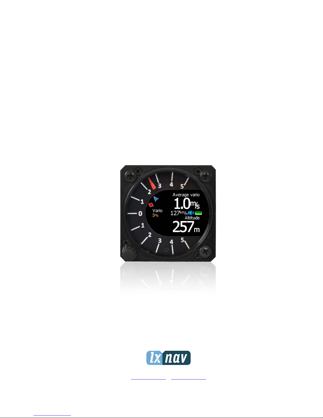
LXNAV V3 is standalone digital vario meter with speed to fly function. The unit has standard
dimensions to fit into a glider panel - 57 mm diameter (2¼"). The unit has integrated high
precision digital pressure sensor, which are sampled more than 100 times per second. Data
is indicated with needle driven with stepper motor and displayed on 320*240 pixel, two-inch,
high brightness colour display. To adjust values and settings, LXNAV V3 has one rotary knob
combined with a push button.
3.1.1 LXNAV V3 Features
• Extremely bright 2" (5 cm) colour display readable in all sunlight conditions with the
ability to adjust the backlight .
• One rotary switch (knob) with push button function is used for input.
• Pre-loaded polar database for almost all gliders.
• Mechanical needle driven by stepper motor indicating vertical speed.
• 240x320 pixels colour screen for additional information such as average, speed to fly,
altitude ...
• Many custom audio settings
• 100Hz sampling rate for very fast response.
• Internal speaker
3.1.2 Interfaces
• Serial RS232 interface
Page 8

V3 Version 1.0 November 2012
Page 8 of 29
• Audio port (Standard 3mm phono jack)
3.1.3 Options
3.1.3.1 External Options
External speaker can be connected as option.
3.1.4 Technical Data
• Power input 6-16 V DC
• Consumption of LXNAV V3 at 12 V:
o 95 mA - minimum brightness without audio.
o 135 mA - maximum brightness without audio.
• 57 mm (2¼") standard aircraft cut-out for the LXNAV V3 vario unit; length 50 mm (not
including connector).
• Weight 156 g
• Antireflective coated glass
Page 9
V3 Version 1.0 November 2012
Page 9 of 29
4 System Description
4.1.1 Push Button
The Rotary switch also has a push button function. LXNAV V3 can detect short or long press
of push button, in most cases short press confirms action, long press cancels action or exits
from the menu Short press means just a click, long press means pushing button for more
than one second.
4.1.1.1 Power Button
The system is powered up using push button. A long press system will turn the V3 off.
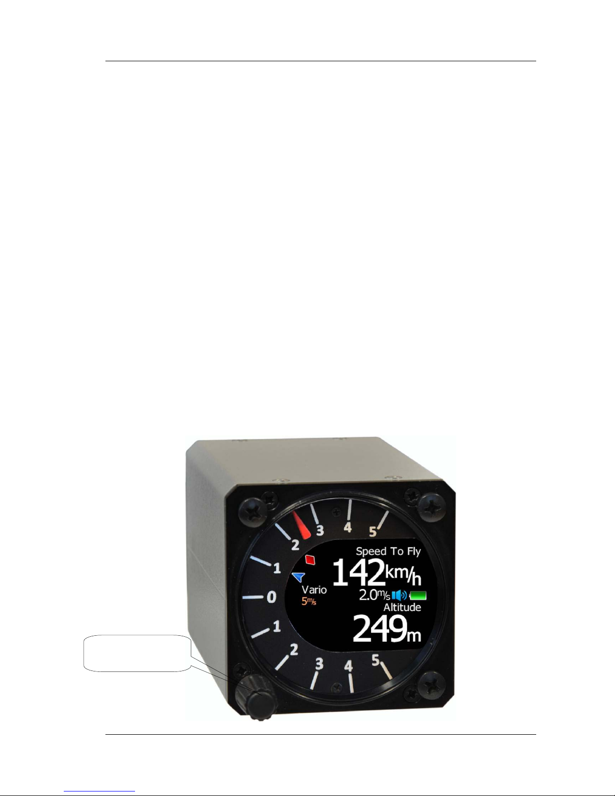
4.2 Rotary Switch
The one rotary switch/knob with integrated pushbutton function can control all functions on
LXNAV V3. Main function is changing of the volume. The rotary switch moves up or down
through the menus. Variables can also be changed using the switch. Pushing the button at
the same time as rotating will step the values in larger increments.
Example 1:
Set elevation menu; normally, values are with step 1m. If you push button in and rotate at
same time, the step will be 10m.
Example 2:
Entering password; Up/Down the numbers are changed. If you press and rotate, the cursor
will move left or right. Short press will move cursor one step right.
Rotary switch with
push button
Page 10

V3 Version 1.0 November 2012
Page 10 of 29
4.3 Switching on the Unit
A short press of the button with turn on the V3. The first LXNAV welcome screen will
appear with some system information (Device name, Version, Serial number...)
When the boot procedure is completed, setup elevation dialogue is shown.
By default setting Set Elevation page is disabled. It can be enabled in Setup QNH
menu.
Push button also has power ON and OFF functions.
4.4 User Input
The LXNAV V3 user interface consists of many dialogues which have different input controls.
They are designed to make input of names, parameters, etc., as easy as possible. Input
controls can be summarised as:
• Text editor
• Spin controls (Selection control)
• Checkboxes
• Slider control
To move the function from one control to another, rotate the rotary knob up or down as
follows:
• Clockwise rotation will select the next control.
• Counter clockwise rotation will select the previous control. PUSH button enters the
selected feature.
4.4.1 Text Edit Control
The Text Editor is used to input an alphanumeric string; the picture below shows typical
options when editing text. Use the knob to change the value at the current cursor position.
Page 11

V3 Version 1.0 November 2012
Page 11 of 29
Push button will move cursor right. Holding push button and rotationg knob, will move
cursor left or right. At last character position, push button will confirm edited value, long
press will cancel editing and exit that control.
4.4.2 “Spin” Control
“Spin” controls are designed for numeric parameters. Rotate the knob to increase/decrease
the selected value. Combination of push button and knob rotation will change the value with
a larger step. .
4.4.3 Selection Control
Selection boxes, also known as combo boxes are used to select a value from a list of
predefined values. Use the page selector to scroll through the list.
4.4.4 Checkbox and Checkbox List
A checkbox enables or disables a particular parameter. Press push button to toggle the
value. If an option is enabled a check mark will be shown, otherwise an empty rectangle will
be displayed.
4.4.5 Slider selector
Some values like volume and brightness are displayed as a slider
With push button you can activate slider control, then with rotation of the knob you can
select the preferred value and confirm it with the push button.
Page 12

V3 Version 1.0 November 2012
Page 12 of 29
4.5 Switching off
By pressing the push button for app. 5 seconds, LXNAV V3 will turn off.
All settings are saved in the power off procedure. We strongly recommend
switching off the unit using push button and not use a separate master switch..
If the system is powered off by a master switch changed data will not be saved.
Flight parameters at takeoff like target altitude and position will remain in stored
memory so your final glide calculations are not affected.
Page 13

V3 Version 1.0 November 2012
Page 13 of 29
5 Operating Modes
LXNAV V3 has three operating modes. A pilot has access to all of them using rotary knob
and push button. The diagram below shows the mode structure of the LXNAV V3.
• Main screen, all navigation and flight parameters defined by pilot
• Quick access, MacCready, Ballast, Bugs.
• Settings, setup of the whole system
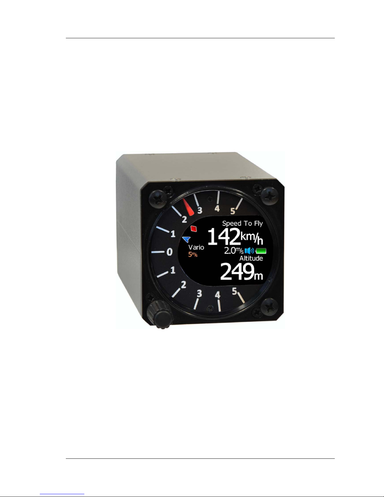
5.1 Main screen and needle
The man screen has a mechanical needle and a 320x240 color display with user selected
data.
Description of LXNAV V3 is shown on next picture.
Mechanical needle displays vario. Printed scale can be chosen (when ordered) in the
range of -5 to 5 or from -10 to 10. Within the software the range can be set to 2.5, 5,
10m/s or 5, 10, 20kts or 500, 1000, 2000fpm.
Upper, middle or lower number can be configured as average vario, altitude, altitude in
feet, flight level, flight time, voltage, speed to fly, absolute pressure .
Red diamond symbol can show average vertical speed.
Blue arrow symbol shows current MacCready value.
Mechanical needle
Average vario symbol
Range
Upper number
Ext. speaker
Middle number
Battery symbol
Lower number
MacCready symbol
Rotary knob & push
button
Page 14

V3 Version 1.0 November 2012
Page 14 of 29
5.2 Quick access menu
A short press of the push button activates the quick access menus. In the last row of
the box is calculated final glide (E) and required speed for that final glide, values
depends on MacCready, Bugs and Ballast setting.
5.3 Settings Mode
In the setup menu users can configure the LXNAV V3. Turn the knob to select the
appropriate setup item. Press the PUSH button to enter a menu. A dialogue or sub-menu
will open.
5.3.1 Logbook
Each flight is stored in logbook.
Because V3 can not receive GPS data, only duration of the flight is written in logbook.
Page 15

V3 Version 1.0 November 2012
Page 15 of 29
5.3.2 QNH
Turn the knob to select the required entry field. Press the PUSH button and start editing
the value.
5.3.2.1 QNH
This feature may be used to offset the altitude datum as the result of pressure changes
during the flight. Since changing the QNH influences the indicated altitude.
5.3.2.2 Set elevation
If Set Elevation – show on start-up, item is not checked, Set elevation menu, will not be
displayed during start up. In this case, elevation will be set to standard QNE (Flight level).
5.3.3 Vario Parameters
This option is used to set the following parameters:
5.3.3.1 Vario needle filter
Sets a time constant of the vario needle. The value can be adjusted between 0.1 and 5 s
with step 1.0 s or 0.1 s. Default value is 1.5 s.
5.3.3.2 Vario range
Sets full scale range of the vario (2.5 m/s, 5 m/s or 10 m/s). Default value is 5 m/s (10 kts).
5.3.3.3 Integrator time
Defines the integration period for the average vario in seconds. The default is 20 seconds.
Page 16

V3 Version 1.0 November 2012
Page 16 of 29
5.3.4 Sounds
In the Sounds setup menu audio settings for the LXNAV V3 and alarms settings can be
modified.
5.3.4.1 Vario Audio mode
Vario audio mode has the following options:
• Linear positive: sound is interrupted with silence every few milliseconds when the
needle is positive; on negative side sound is linear (not interrupted).
• Linear negative: inverse function to Linear positive.
• Linear: sound is linear and non-interrupted in full scale range.
• Digital positive: similar to Linear positive, except frequency is not changing linearly
but with larger steps.
• Digital negative: inverse function to Digital positive.
• Linear positive only: sound is present only at positive values, for negative values there
is silence.
• Digital positive only: similar function to Linear positive only, except the sound is
similar to the digital tone.
5.3.4.2 Audio frequencies
• Freq at 0% defines the tone frequency at 0 m/s.
• Freq at +100% defines the tone frequency at full + deflection.
• Freq at -100% defines the tone frequency at full – deflection.
Page 17

V3 Version 1.0 November 2012
Page 17 of 29
5.3.5 Units
Use this menu to specify units, UTC time offset and type of ballast input.
• Load, which is entered in kg/m
2
or lb/ft2.
• Weight of water ballast, which is entered in kg or lb . If this option is used the weights
of the glider and pilot must be entered. Refer to Chapters 5.3.7 for more details of how
to enter glider and pilot weights.
• Ballast can be displayed as Overload factor or Wing Load or just weight of ballast.
Page 18

V3 Version 1.0 November 2012
Page 18 of 29
5.3.6 Display
The display menu controls screen brightness.
• Use Brightness control to adjust intensity of the LCD backlight.
• Upper, Middle and Lower Numeric Display: The parameter displayed can be
configured. Following parameters can be displayed: average vertical speed, flight time,
Altitude, Altitude in ft, Flight level, Battery voltage, absolute pressure.
5.3.7 Polar and Glider
Use this dialogue to enter glider polar and other glider properties. As a default polar a
standard class glider is enabled automatically .
Page 19

V3 Version 1.0 November 2012
Page 19 of 29
Polars for most modern gliders are already prepared. Use Glider type control, to list between
preloaded glider polars.
All glider data will be copied from the chosen polar. The check the best glide ratio and
minimum sink rate, to see if the polar data matches the glider performance, you may look in
MacCready setting menu. You can modify the polar by changing coefficients a, b and c. A
polar is defined as a quadratic equation with the parameters a, b, and c. Use the SeeYou
program (Tools->Polar) to calculate coefficients a, b and c for a given glider’s polar. The
program requires three sink points entered at selected speeds (e.g.: 100 km/h, 130 km/h,
and 150 km/h). The program will calculate the values of a, b and c, which should be noted
and entered into the LXNAV V3.
Stall speed is used to generate stall warnings which are available only with integrated Voice
module (Not integrated in LXNAV V3).
Weights must be entered and user should enter ballast in kilograms. There are three
weights to enter. Min. Weight
(Minimum glider weight)
corresponds to the min.load value
and represents the value at which the polar was measured or recalculated. Max. weight
(Maximum glider weight)
is the maximum take-off weight allowed for a glider. It is not used
in the calculation, it is just a reminder to the pilot of the maximum take-off weight. Empty
weight
(Empty glider weight)
is weight of the glider without pilot and ballast. The overload
factor is calculated as:
weightgliderMinimum
ballastWaterweightPilotweightgliderEmpty
overload
..
....
+
+
=
Empty glider weight is a weight of empty glider. This number can be found in a glider
book.
Pilot weight is weight of the pilot with parachute and baggage.
Water ballast is a weight of ballast.
Minimum glider weight is a
weight of empty glider + minimum pilot weight.
This value is
useful for when we want to display ballast in weight (kg or lbs).
Maximum glider weight is MTOW (
max. takeoff weight
) – this value is used only to limit
pilot to enter higher ballast, as is allowed with MTOW.
5.3.8 Password
There are several passwords which run specific procedures as listed below:
• 00666 Resets all settings to factory default
• 99999 will clean logbook
• 01048 can adjust needle to zero
Do not adjust needle when airborne.
Page 20

V3 Version 1.0 November 2012
Page 20 of 29
5.3.9 About
In about page is information about firmware versions, hardware versions and serial
numbers.
Page 21

V3 Version 1.0 November 2012
Page 21 of 29
6 Variometer and Altimeter
All signals from the pneumatic sensor (altitude) is derived from high quality pressure sensor
which mean that no flask is necessary. The vario signal is derived from the altitude signal.
Altitude sensor has temperature compensation. Mechanical needle and colour display show
the vario information as well as many other parameters.
The display is user configurable. The variometer can be configured to show:
• Range 5, 10 and 2.5 m/s or 10, 20 and 5 kts.
• time constants 0.1 s to 5 s, in addition there are 4 settings for electronic processing
for the vario signal.
Vario indications can be corrected for total energy with a TE probe. The quality of the TE
compensation depends entirely on the location, size and dimension of the TE tube. The
installation must be leak-proof.
Compensation with TE probe
6.1 Altimeter
The altimeter of the LXNAV V3 is temperature compensated from -20ºC up to + 60ºC. The
altimeter is calibrated up to 20000 m.
6.2 Speed to fly
Speed to fly is based on the MacCready theory is a very useful tool to optimise cross-country
speed. The pilot must follow Speed to fly value on pneumatic airspeed indicator. Speed to
fly is calculated from polar of glider, actual sink rate (vario), MacCready setting, Ballast and
Bug setting.
TE (Pst)
LXNAV V3
Page 22

V3 Version 1.0 November 2012
Page 22 of 29
7 Flying with the LXNAV V3
To get the best out of the LXNAV V3 it is important that some preparation is done prior to
take-off. Trying to configure the instrument or set a task while flying is very hazardous
especially in a competition. At the least, it could spoil your whole day! Pre-flight preparation
will ensure that the flight will be both safe and enjoyable.
7.1 On the Ground
7.1.1 Power on Procedure
Press the push button. LXNAV V3 welcome screen will appear. The first screen shows the
version of the boot loader, firmware, hardware and serial number. The boot procedure
normally takes few seconds. When completed, Set Elevation dialogue is shown.
7.1.2 Set Elevation and QNH
This setting is crucial for final glide calculation: therefore pay careful attention to it.
LXNAV V3 can’t calculate final glide.
The instrument will offer elevation over standard pressure level QNE. Use the knob to finetune the elevation.
7.1.3 Pre-flight Check
After elevation setup the LXNAV V3 will switch to normal operation mode.
It is recommended that the MacCready, ballast and bugs settings be set to match the
current glider configuration. Press the push button. The dialogue for MacCready, Ballast
and Bugs will appear.
Page 23

V3 Version 1.0 November 2012
Page 23 of 29
Use the rotary knob to modify the MacCready setting.
Page 24

V3 Version 1.0 November 2012
Page 24 of 29
8 Installation
The LXNAV V3 requires a standard 57 mm cut-out.
One pressure connector is fitted to the back of the V3 vario. It’s total energy (TE) pressure
connector
8.1 Installing the LXNAV V3
The LXNAV V3 vario should be mounted in a standard 57 mm hole.
Remove rotary knob cap with a knife or flat screw driver, then hold knob and unscrew it.
Remove remaining three screws. Install V3 into the panel, screw back all screws and knob.
Make sure that between knob and panel is some space, to push button.
Be sure that LXNAV V3 is placed far enough from compass. Inside is stepper
motor and speaker which generates magnetic field interferences.
8.2 Connecting LXNAV V3
LXNAV V3 is connected to 12V DC power supply. Red wire goes to + positive and blue wire
goes to – ground.
Instrument has no internal fuse. 3A external fuse is required! Power supply
cables should use a minimum of 0.5 mm² wires.
Page 25

V3 Version 1.0 November 2012
Page 25 of 29
8.3 Cutout of V3
8.4 Ports and Wiring
8.4.1 LXNAV V3 ports
Ext. speaker
TE probe or
Static
Internal speaker
Main power port
Page 26

V3 Version 1.0 November 2012
Page 26 of 29
8.4.2 Main port
On main port is connected V3 wiring.
8.4.2.1
1 2 3 4 5 6
Pin numbers
Pin number Description
1 12V power supply
2,3 N.C.
4 (input) Receive to LXNAV V3 RS232
5 (output) Transmit from LXNAV V3 RS232
6 Ground
In the moment, serial interface is used only for firmware update.
8.4.3 External Audio port
Here is connected optional external speaker with standard 3mm mono phono jack.
LXNAV V3 has built in internal speaker.
Page 27

V3 Version 1.0 November 2012
Page 27 of 29
9 Firmware Update
Firmware updates of the LXNAV V3 can be easily carried out using PC. Please visit our
webpage www.lxnav.com
and check for the updates.
You can also subscribe to a newsletter to receive news about the LXNAV V3 automatically.
9.1 Updating LXNAV V3 firmware using PC
For update we need V3 cable with serial RS232 interface and free serial port on your PC. If
your PC has no serial ports, you can use USB to SERIAL converter.
1. Download the latest firmware and update tool from our web site, section
downloads/firmware http://www.lxnav.com/download/firmware.html
. Firmware is
compressed in a zip file. App_VTRI_x.yy.lxfw.
2. Unpack file to one folder and run FlashLoader485App.exe (PC update tool)
3. Choose firmware file App_VTRI_x.yy.lxfw
4. Choose correct serial port and baud rate (115200bps)
5. Press “Flash” Button.
6. Turn ON V3
7. If update starts, you will see a progress on PC and on V3.
If update procedure is interrupted of any case. LXNAV V3 will not start. It will
cycle in bootloader application with red message “Flash integrity failed”.
Bootloader application is waiting to receive new firmware from PC . After
Page 28

V3 Version 1.0 November 2012
Page 28 of 29
successfull firmware update LXNAV V3 will start again.
Update cable is not included with V3.
Page 29

V3 Version 1.0 November 2012
Page 29 of 29
10 Revision History
November 2012 Initial release of owner manual
November 2012 Corrected Ch.5.3.3.4, removed Ch.5.3.5
 Loading...