

Page 1
S80 Version 4.92 November 2014
Page 1 of 61
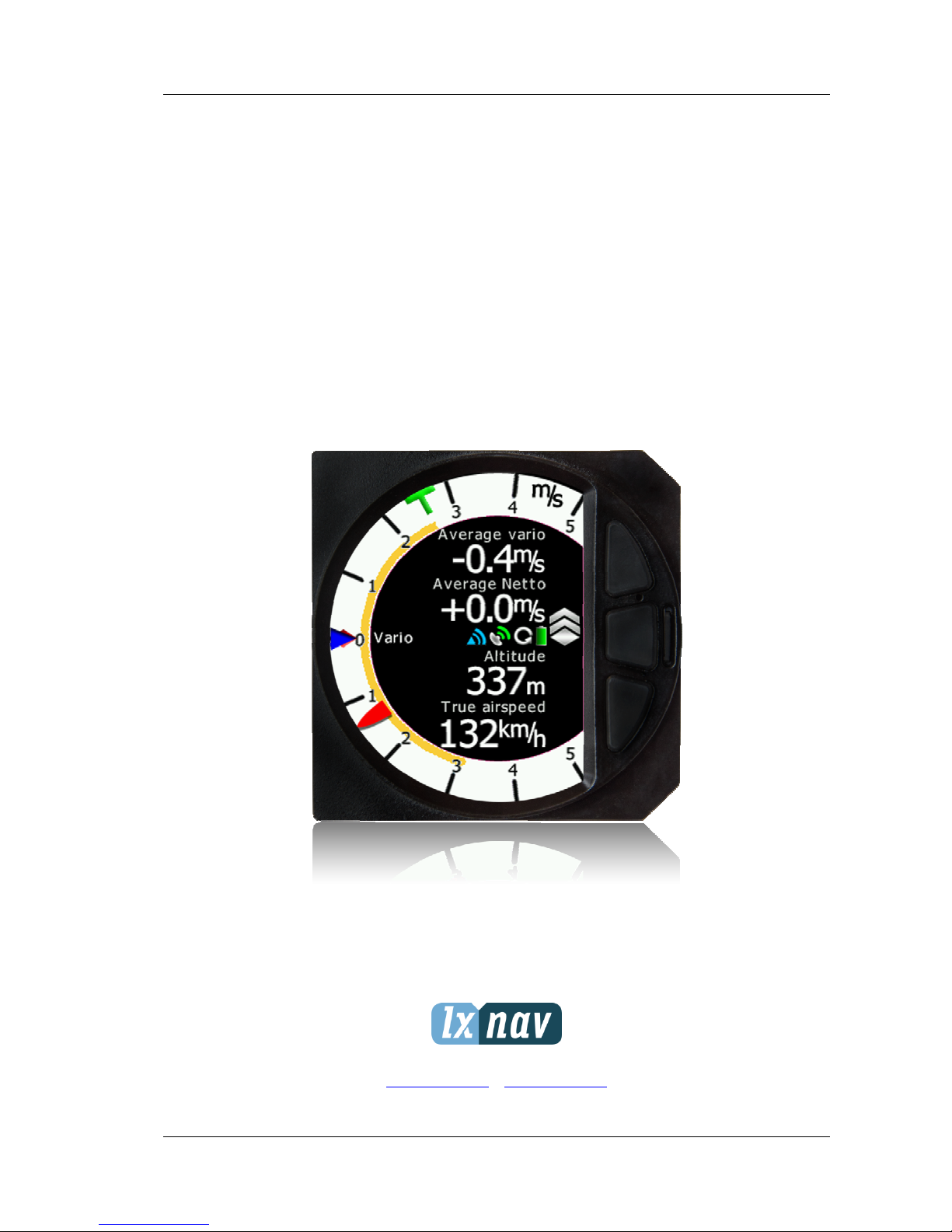
S80
Digital speed to fly variometer, final glide calculator and
navigation system with simple moving map.
Version 4.92
LXNAV d.o.o. • Kidričeva 24a, 3000 Celje, Slovenia • tel +386 592 33 400 fax +386 599 33 522
info@lxnav.com • www.lxnav.com
Page 2

S80 Version 4.92 November 2014
Page 2 of 61
1 Important Notices 5
1.1 Limited Warranty 5
2 Packing Lists 6
3 Basics 7
3.1 LXNAV S80 at a Glance 7
3.1.1 LXNAV S80 Features 7
3.1.2 Interfaces 8
3.1.3 Options 8
3.1.3.1 External Options 8
3.1.4 Technical Data 8
4 System Description 9
4.1.1 Push Button 9
4.1.1.1 Power Button 9
4.2 Rotary Switches 9
4.3 Switching on the Unit 10
4.4 User Input 11
4.4.1 Text Edit Control 11
4.4.2 “Spin” Control 11
4.4.3 Selection Control 12
4.4.4 Checkbox and Checkbox List 12
4.4.5 Slider selector 13
4.5 Switching off 13
5 Operating Modes 14
5.1 Info Screen 15
5.1.1 Quick access menu 15
5.2 Flarm Screen 15
5.2.1 Quick access menu 16
5.2.2 Flarm warnings 16
5.3 Waypoint Screen 17
5.3.1 Quick access menu 17
5.3.1.1 Navboxes Option 18
5.3.1.2 Editing Navboxes 19
5.3.2 Second Waypoint Page (Numerical Data) 19
5.3.3 Third Waypoint Page (AHRS) 21
5.4 Task Screen 21
5.4.1 Quick access menu 22
5.4.2 Second Task Page (Numerical Data) 23
5.4.3 Third Task Page (AHRS) 24
5.5 Setup Screen 24
5.5.1 QNH & RES 25
5.5.1.1 QNH 26
5.5.1.2 Safety Altitude 26
5.5.2 Vario Param. 27
5.5.2.1 Vario needle filter 27
5.5.2.2 Vario sound filter 27
5.5.2.3 Netto filter 27
5.5.2.4 Relative filter 27
5.5.2.5 SC filter 27
5.5.2.6 Smart Filter 27
5.5.2.7 Needle range 28
Page 3

S80 Version 4.92 November 2014
Page 3 of 61
5.5.2.8 Dead Band (SC tab) 28
5.5.2.9 Auto SC 28
5.5.2.10 Vario Average Time 28
5.5.2.11 Netto Average Time 28
5.5.2.12 Temperature Offset 28
5.5.2.13 Inertial assisted vario 28
5.5.3 Display 29
5.5.3.1 Automatic Brightness 29
5.5.3.2 Minimum Brightness 29
5.5.3.3 Maxximum Brightness 29
5.5.3.4 Brightness 29
5.5.4 Graphics 29
5.5.4.1 Graphics – Flarm 30
5.5.4.1.1 Colours can be set for the following: 30
5.5.4.1.2 Label Text 30
5.5.4.1.3 Active Timeout 31
5.5.4.1.4 Inactive Timeout 31
5.5.4.1.5 Draw Line to selected Target 31
5.5.4.1.6 Draw History 31
5.5.4.1.7 Plane icon size 31
5.5.4.2 Graphics – Airsp. & Tsk. 31
5.5.5 Sounds 32
5.5.5.1 Equalizer Option 32
5.5.5.2 Vario Sounds 33
5.5.5.3 Flarm Sounds 34
5.5.6 Warnings 35
5.5.7 Obs. Zones 35
5.5.8 Units 36
5.5.9 Hardware 37
5.5.9.1 TE compensation 38
5.5.9.2 SC switch 39
5.5.9.3 Digital Input 1 and 2 39
5.5.10 Indicator setup 39
5.5.11 Comms. Setup 40
5.5.12 Battery Chemistry Setup 40
5.5.13 Files 41
5.5.13.1 Waypoints File 42
5.5.13.2 Airspace File 42
5.5.13.3 Flarmnet File 43
5.5.14 Polar and Glider 44
5.5.15 Password 45
5.5.15.1 List of Password functions 46
5.5.16 About 46
6 Variometer and Altimeter 47
6.1 Altimeter 47
6.2 Speed Command 47
7 Flying with the LXNAV S80 48
7.1 On the Ground 48
7.1.1 Power on Procedure 48
7.1.2 Set Elevation and QNH 48
7.1.3 Pre-flight Check 49
7.2 Airborne 49
Page 4

S80 Version 4.92 November 2014
Page 4 of 61
7.2.1 Final glide calculation 49
8 Installation 50
8.1 Installing the LXNAV S80 51
8.2 Connecting LXNAV S80 51
8.3 Cutout of S80 51
8.4 Available cables for GPS and PDA ports 52
8.5 Installation of options 52
8.5.1 S80D option (S80 repeater) 53
8.5.1.1 Data Exchange 53
8.5.1.2 Cable Wiring (LXNAV S80D) 53
8.5.2 Magnetic compass (Compass -CAN) 53
8.5.3 Remote stick (Remote-CAN) 53
8.5.4 AHRS option 54
8.6 Ports and Wiring 54
8.6.1 LXNAV S80 ports 54
8.6.2 LXNAV S80 wiring 56
8.7 Configurations 56
8.7.1 NANO – S80 – OUDIE 56
8.7.2 NANO – S80 – MINIMAP 57
8.7.3 Nano3– S80 – OUDIE 57
8.7.4 COLIBRI2 – S80 – OUDIE 57
8.7.5 COLIBRI,VOLKSLOGGER– S80 – OUDIE 58
8.7.6 Flarm/RedBox– S80 – OUDIE 58
8.7.7 FlarmMouse - FlarmView -S80 - OUDIE 58
8.7.8 FlarmMouse – S80 – OUDIE 59
9 Firmware Update 60
9.1 Updating LXNAV S80 firmware using micro SD card 60
10 Revision History 61
Page 5

S80 Version 4.92 November 2014
Page 5 of 61
1 Important Notices
The LXNAV S80 system is designed for VFR use only as an aid to prudent navigation. All
information is presented for reference only. Terrain, airports and airspace data are provided
only as an aid to situation awareness.
Information in this document is subject to change without notice. LXNAV reserves the right
to change or improve their products and to make changes in the content of this material
without obligation to notify any person or organisation of such changes or improvements.
A Yellow triangle is shown for parts of the manual which should be read carefully
and are important for operating the LXNAV S80 system.
Notes with a red triangle describe procedures that are critical and may result in
loss of data or any other critical situation.
A bulb icon is shown when a useful hint is provided to the reader.
1.1 Limited Warranty
This LXNAV S80 product is warranted to be free from defects in materials or workmanship
for two years from the date of purchase. Within this period, LXNAV will, at its sole option,
repair or replace any components that fail in normal use. Such repairs or replacement will
be made at no charge to the customer for parts and labour, the customer shall be
responsible for any transportation cost. This warranty does not cover failures due to abuse,
misuse, accident, or unauthorised alterations or repairs.
THE WARRANTIES AND REMEDIES CONTAINED HEREIN ARE EXCLUSIVE AND IN LIEU OF
ALL OTHER WARRANTIES EXPRESSED OR IMPLIED OR STATUTORY, INCLUDING ANY
LIABILITY ARISING UNDER ANY WARRANTY OF MERCHANTABILITY OR FITNESS FOR A
PARTICULAR PURPOSE, STATUTORY OR OTHERWISE. THIS WARRANTY GIVES YOU
SPECIFIC LEGAL RIGHTS, WHICH MAY VARY FROM STATE TO STATE.
IN NO EVENT SHALL LXNAV BE LIABLE FOR ANY INCIDENTAL, SPECIAL, INDIRECT OR
CONSEQUENTIAL DAMAGES, WHETHER RESULTING FROM THE USE, MISUSE, OR
INABILITY TO USE THIS PRODUCT OR FROM DEFECTS IN THE PRODUCT. Some states do
not allow the exclusion of incidental or consequential damages, so the above limitations may
not apply to you. LXNAV retains the exclusive right to repair or replace the unit or software,
or to offer a full refund of the purchase price, at its sole discretion. SUCH REMEDY SHALL
BE YOUR SOLE AND EXCLUSIVE REMEDY FOR ANY BREACH OF WARRANTY.
To obtain warranty service, contact your local LXNAV dealer or contact LXNAV directly.
October 2014 © 2014 LXNAV. All rights reserved.
Page 6
S80 Version 4.92 November 2014
Page 6 of 61
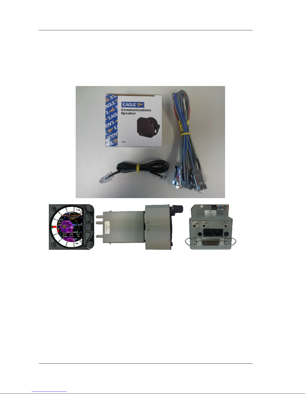
2 Packing Lists
• LXNAV S80
• Main power cable for S80 + CAN terminator
• Speaker
• GPS cable - S80-GPS-IGC
Page 7

S80 Version 4.92 November 2014
Page 7 of 61
3 Basics
3.1 LXNAV S80 at a Glance
LXNAV S80 is standalone digital vario meter, final glide calculator and navigation system with
simple moving map. The LXNAV S80 has both GPS/Flarm and PDA/PNA inputs/outputs. The
unit has standard dimensions that will fit into a glider panel with an opening of - 80 mm
diameter (3.15”). It is also able to supply PDA/PNA with power (5VDC/1A). The unit has an
integrated high precision digital pressure sensor and inertial system. The sensors are
sampled more than 100 times per second. Real time Data is indicated with the vario needle,
airspace map and up to 4 variable number fields displayed on QVGA 320x240 pixel, 3.5 inch,
high brightness (1200 nits) colour display. To adjust values and settings, the LXNAV S80 has
two rotary push button knobs and three additional push buttons.
The LXNAV S80 can be expanded with one or more repeaters (LXNAV S80D) through the
CAN bus.. This allows both pilots in a two seat glider to have equal control of all functions
from the front or the rear seat.
3.1.1 LXNAV S80 Features
• Extremely bright 3.5’’ 8.9cm QVGA colour display readable in all sunlight conditions
with the ability to adjust the backlight .
• Two rotary switches (knobs) with push button function and three push buttons are
used for input.
• Pre-loaded polar database for almost all gliders.
• GPS/Flarm and PDA/PNA inputs/outputs
• Flarm Indication, if Flarm is connected to the GPS/Flarm port
• Needle indicating various data such as netto vertical speed, relative (super netto) and
vertical speed (vario).
• 320x240 pixels colour screen for additional information such as average, thermal
vario, time, speed etc…
• Many custom audio settings
Page 8

S80 Version 4.92 November 2014
Page 8 of 61
• 100Hz sampling rate for very fast response.
• Speed to fly indication.
• TE compensation can be selected to be either pneumatic TE probe or electronic TE.
• Multilanguage user interface - in a future firmware release
• Audio equalizer, for custom vario sound performance
3.1.2 Interfaces
• GPS/Flarm port input/output on RS232 level (Standard IGC RJ11 connector)
• PDA port input/output on RS232 or LV-TTL (3.3V) level for PNA devices (RJ45 connector)
• Audio port (Standard 3mm phono jack)
• 1Mbit CAN bus for extension to S80D repeater
3.1.3 Options
3.1.3.1 External Options
By using a CAN bus system, a second seat device can be connected. The unit installed in the
rear seat of the glider is independently powered and receives all the necessary data from the
main unit. The communication between both units is exclusively via the CAN bus system.
3.1.4 Technical Data
Power input 10-16 V DC
Consumption of LXNAV S80 at 12 V:
140 mA - minimum brightness without audio.
190 mA - maximum brightness without audio.
Consumption of LXNAV S80D at 12 V:
90 mA - minimum brightness without audio.
140 mA - maximum brightness without audio.
80 mm (3.15") standard aircraft cut-out for the LXNAV S80 indicator unit; 80x80x45mm •
Sensor box: 65x45x85mm (not including connector).
Weight 460g (290g for S80D)
Page 9
S80 Version 4.92 November 2014
Page 9 of 61
4 System Description
4.1.1 Push Button
The two Rotary switches have a push button function. LXNAV S80 can detect short or long
press of the push button. A short press means just a click, a long press means pushing the
button for more than one second.
4.1.1.1 Power Button
The system is powered up using any of the push buttons or a short press of any of the
rotary knobs. A long press of the upper rotary knob system will turn the S80 off.
4.2 Rotary Switches
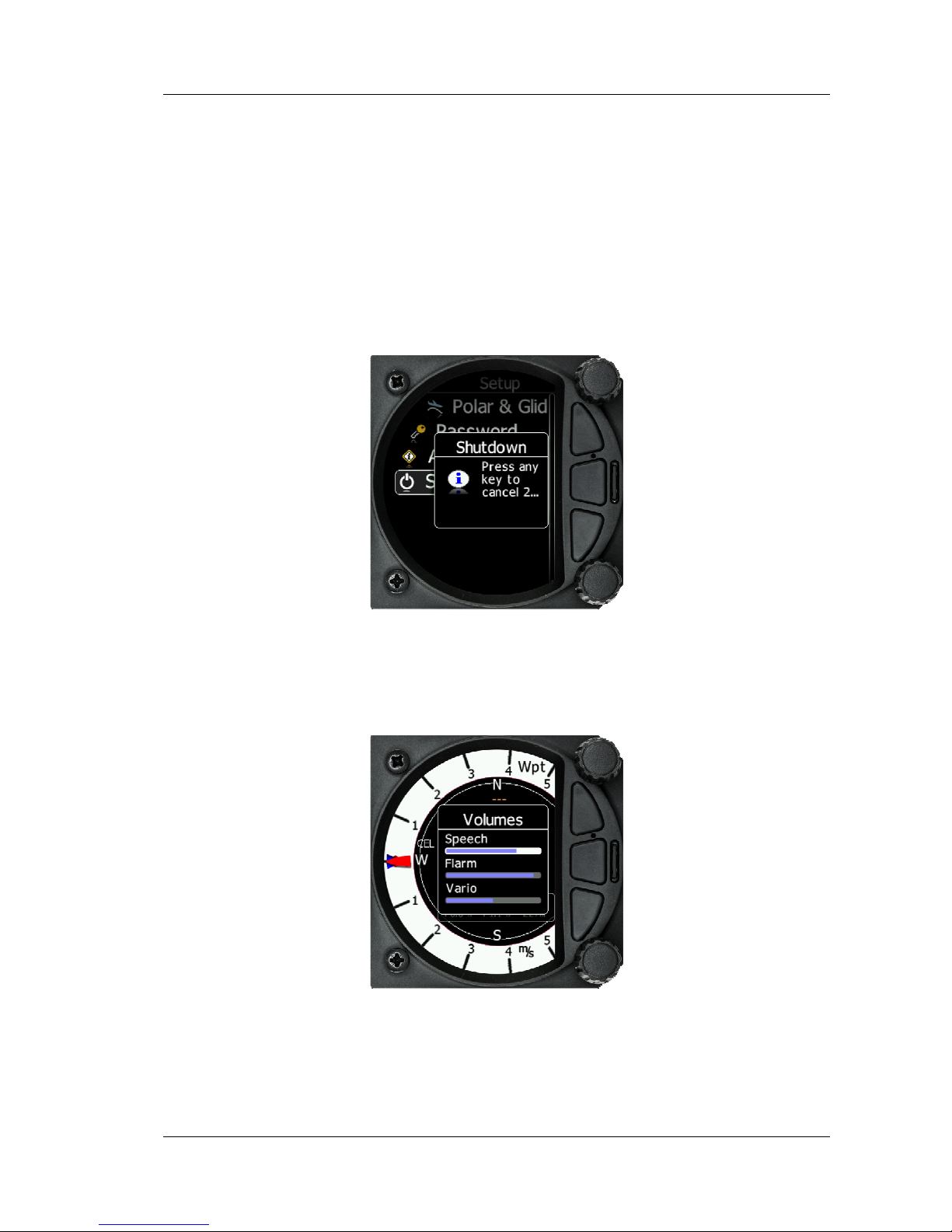
The upper rotary knob is designed for direct volume control. Pushing the upper rotary knob,
the user can set the volume for the Vario, Speech and Flarm beep. The system can be shut
down using a long press of the upper rotary knob.
The Lower rotary knob is used for MC and other settings. With the lower rotary pushbutton,
we can toggle between MC, Bal and Bugs settings. In all other menus, this knob is used for
setting values and editing texts…
Page 10
S80 Version 4.92 November 2014
Page 10 of 61
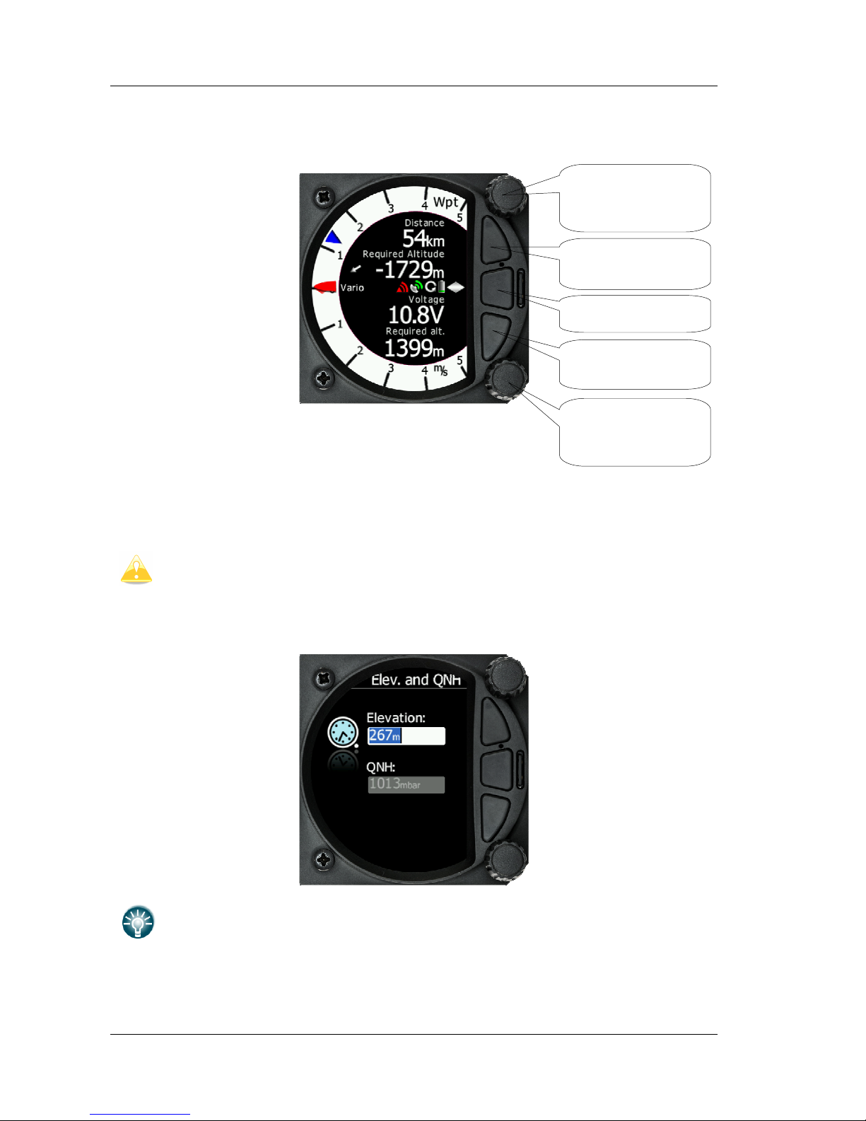
The three buttons between the two rotary knobs have fixed functions. The top button is ESC
(CANCEL), the middle is menu and the lower button is the ENTER (OK) button.
4.3 Switching on the Unit
A short press of any of the buttons or rotary knobs will turn on the S80. The first LXNAV
welcome screen will appear with the system information (Device name, Version, Serial
number...)
S80D rear seat unit cannot be powered up if the S80 is not already powered up.
When the boot procedure is completed, the setup elevation dialogue is shown.
Push button also has power ON function.
Rotary switch with
push button
(Volume)
Rotary switch with
push button
(Selector)
Push button Esc
(Cancel)
Push button Menu
Push button Enter
(Ok)
Page 11
S80 Version 4.92 November 2014
Page 11 of 61
4.4 User Input
The LXNAV S80 user interface consists of dialogues which have different input controls.
They are designed to make the input of names, parameters, etc., as easy as possible. Input
controls can be summarised as:
• Text editor
• Spin controls (Selection control)
• Checkboxes
• Slider control
To move the function from one control to another, rotate the lower rotary knob as follows:
• Clockwise rotation will select the next control.
• Counter clockwise rotation will select the previous control. PUSH button enters the
selected feature.
• Faster rotation of the rotary knob will increase the rate at which the value changes. i.e.
bigger steps in value.
4.4.1 Text Edit Control
The Text Editor is used to input an alphanumeric string; the picture below shows typical
options when editing text/numbers. Use the bottom rotary knob to change the value at the
current cursor position.
Turn the bottom rotary Knob to set the character and then press the enter key to move to
the next charachter to the right. Press the escape key to move back to the left. When you
have finished editing, press the Enter key. Pressing the bottom rotary knob will enter or exit
a controll.
4.4.2 “Spin” Control
“Spin” controls are designed for numeric parameters. Rotate the knob to increase/decrease
the selected value. To increase the values in larger steps, spin the bottom rotary knob
control faster!
Page 12
S80 Version 4.92 November 2014
Page 12 of 61
4.4.3 Selection Control
Selection boxes, also known as combo boxes are used to select a value from a list of
predefined values. Use the bottom rotary knob to scroll through the list.
4.4.4 Checkbox and Checkbox List
A checkbox enables or disables a particular parameter. Press the bottom rotary knob to
toggle the value. If an option is enabled a check mark will be shown, otherwise an empty
rectangle will be displayed.
Page 13
S80 Version 4.92 November 2014
Page 13 of 61
4.4.5 Slider selector
Some values, like volume and brightness are displayed as a slider
With a push of the rotary button you can activate the slide control, then with rotation of the
knob you can select the preferred value and confirm it with the push button.
4.5 Switching off
Switching the unit off is archived by selecting the shutdown option within the Setup menu.
By using this method of shut down, all your settings are saved.
All settings are saved during the power off procedure. We strongly recommend
switching off the unit using the shutdown option in the settings menu.
If the system is powered off by the master switch, changed data will not be
saved. Flight parameters at takeoff such as target altitude and position will
remain in the stored memory so your final glide calculations are not affected.
Page 14
S80 Version 4.92 November 2014
Page 14 of 61
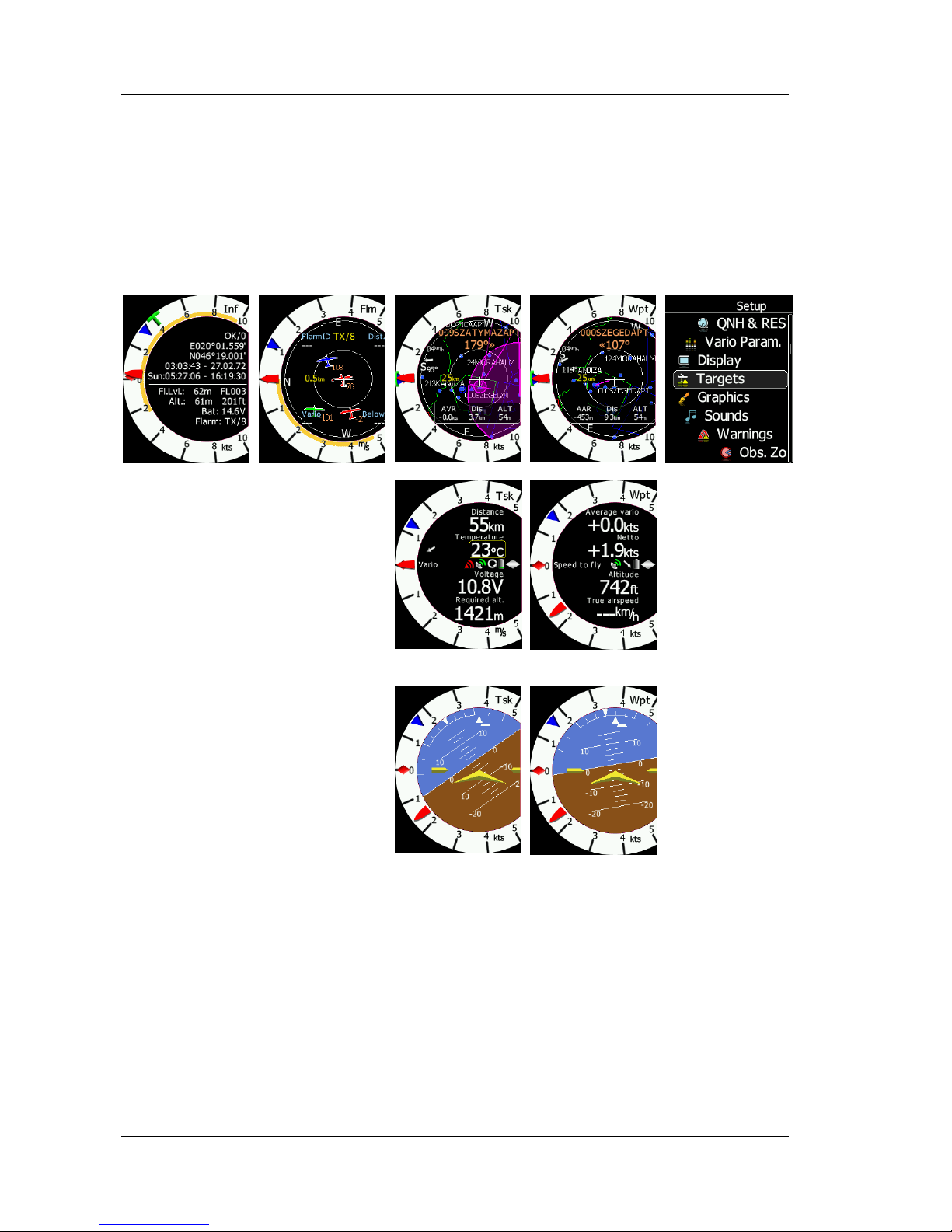
5 Operating Modes
LXNAV S80 has five operating modes. A pilot has access to all of them using the middle
menu push button. The diagram below shows the mode structure of the LXNAV S80.
Info
mode
Flarm
mode
Task
Mode
Waypoint
mode
Setup
mode
• Info Screen: Contains the GPS data from the GPS source Altitude and Battery voltage
• Flarm Screen: Showing Flarm targets in range (if a Flarm device is connected to the
GPS port)
• Waypoint screen: Simple navigation screen to a waypoint
• Task Screen: Task screen showing the task and airspace
• Setup screen: For all aspects of the setup of the S80
Page 15
S80 Version 4.92 November 2014
Page 15 of 61
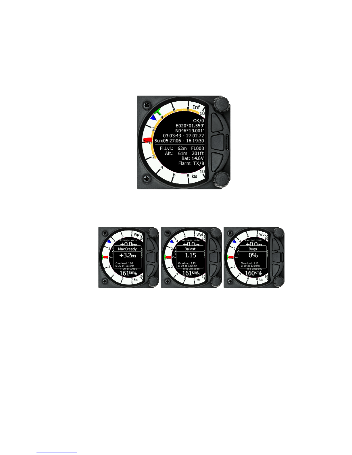
5.1 Info Screen
The Info Screen gives you a snapshot of the GPS position, date, and time along with
Flight level, altitude, Battery status, and Flarm status. Flight Level equivalent is also
available in meters as is the Altitude.
5.1.1 Quick access menu
A short press of the push button activates the quick access menu. Mc, Bugs and Bal
are available.
To change the MacCready value, rotate the bottom rotary knob. A short press on the
bottom rotary knob moves to the Ballast scree and stores the MacCready setting.
Pressing the bottom rotary knob again will open the Bugs screen. If no action is
performed for 3 seconds, the screen will close.
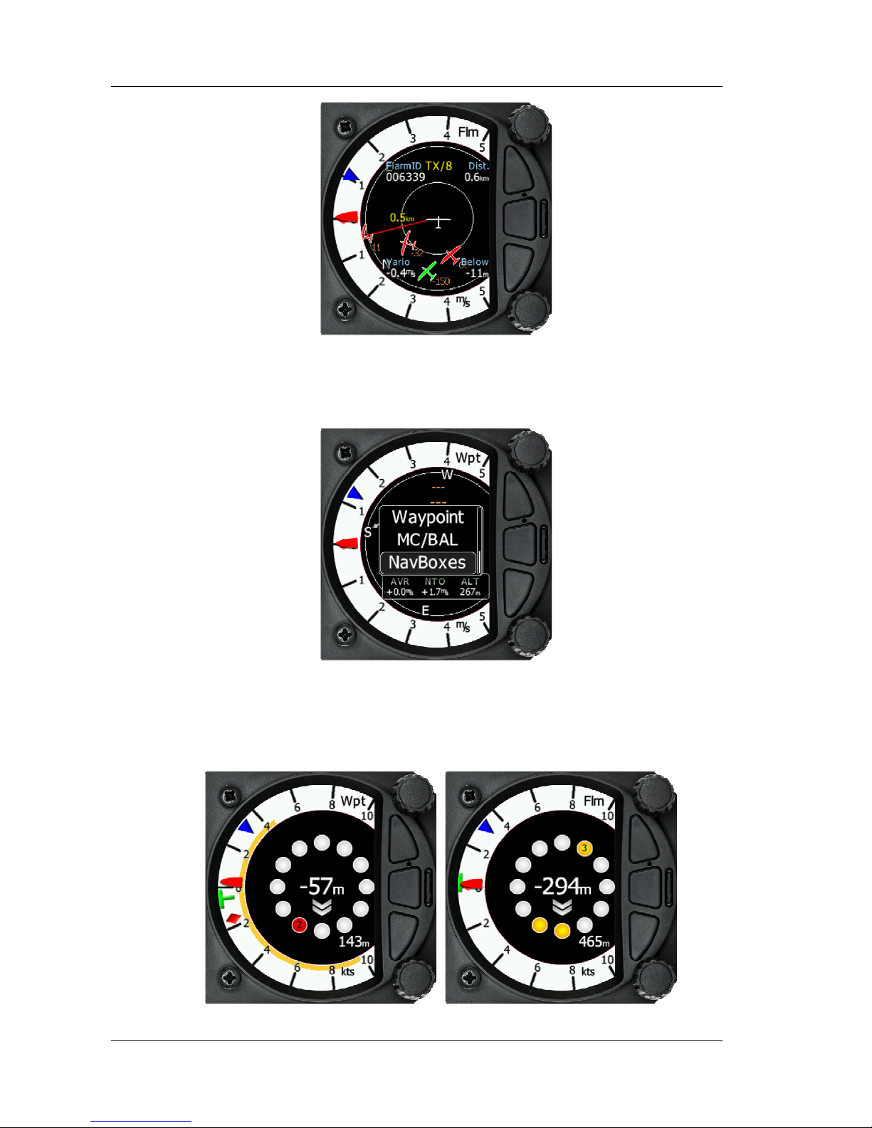
5.2 Flarm Screen
If the S80 is connected to a Flarm source through the GPS port then the Flarm screen
will display a map of relative positions of Flarm targets in range. By rotating the
bottom rotary knob, you can change the range of the display from 1km to 100km
Page 16
S80 Version 4.92 November 2014
Page 16 of 61
5.2.1 Quick access menu
A short press of the push button activates the quick access menu. Three options, Mc,
Bugs and Bal are available
5.2.2 Flarm warnings
Regardless of which screen you are on, if a Flarm target triggers an urgent or
important warning then the screen will change to the Flarm warning screen
Page 17
S80 Version 4.92 November 2014
Page 17 of 61
The central number and chevrons indicate if the Flarm target is bellow or above and
by how many meters/feet. The number in the bottom left indicates the range in
meters/feet.
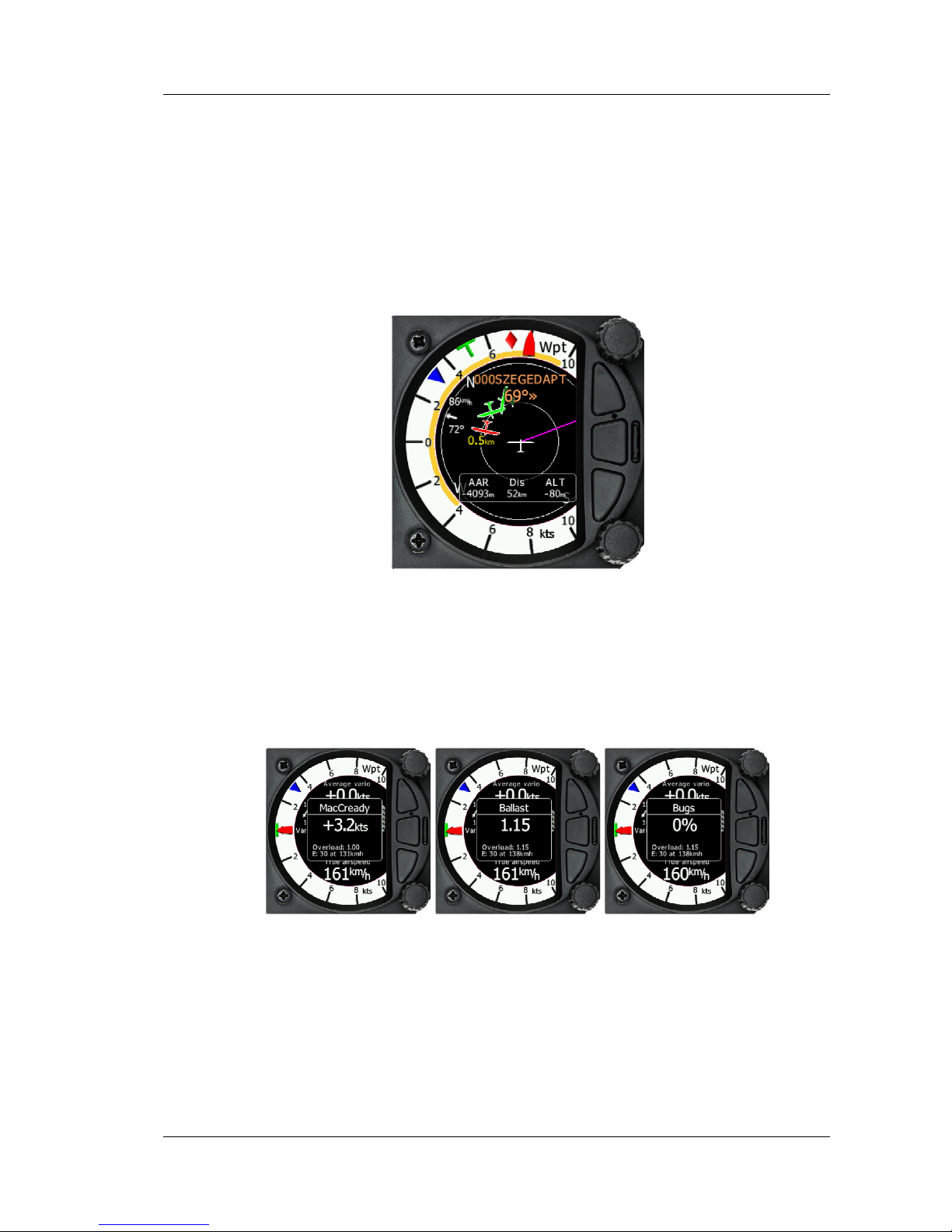
5.3 Waypoint Screen
The Wpt screen is a quick access screen to provide simple navigation to a Waypoint or
Airport. By rotating the bottom rotary knob, you can change the range of the display
from 1KM to 100Km
The first page shows a line to a selected waypoint, the name of the selected waypoint
at the top of the screen and the relative bearing and chevrons indicating the direction
to turn towards the selected waypoint. (The Navboxes can be configured with distance
and arrival Altitude.)
5.3.1 Quick access menu
A short press of the push button activates the quick access menu.
To change the MacCready value, rotate the bottom rotary knob. A short press on the
bottom rotary knob moves to the Ballast scree and stores the MacCready setting.
Pressing the bottom rotary knob again will open the Bugs screen. If no action is
performed for 3 seconds, the screen will close.
Page 18
S80 Version 4.92 November 2014
Page 18 of 61
To Select a waypoint, use the bottom rotary knob to highlight the select option and
then press once. This will open the Waypoint list
The Waypoint can be selected from the alphabetical list of waypoints. (See uploading
files section Error! Reference source not found.). Rotating the bottom rotary Knob
moves you through the waypoint list in alphabetical order, clockwise increasing the
value, Anti Clockwise, decreasing the value. To select the first letter of the desired
waypoint, press the Enter button (bottom of the three buttons) this moves the cursor
to the second letter. Rotate the bottom rotary knob until the second letter of the
required Waypoint is highlighted and then press Enter. Repeat the process until the
required waypoint is the only selection available. You can then either press the enter
button or press the bottom rotary Knob to select the Waypoint. The screen will then
change back to the navigation page and show a line to the Waypoint, Waypoint name
and relative bearing.
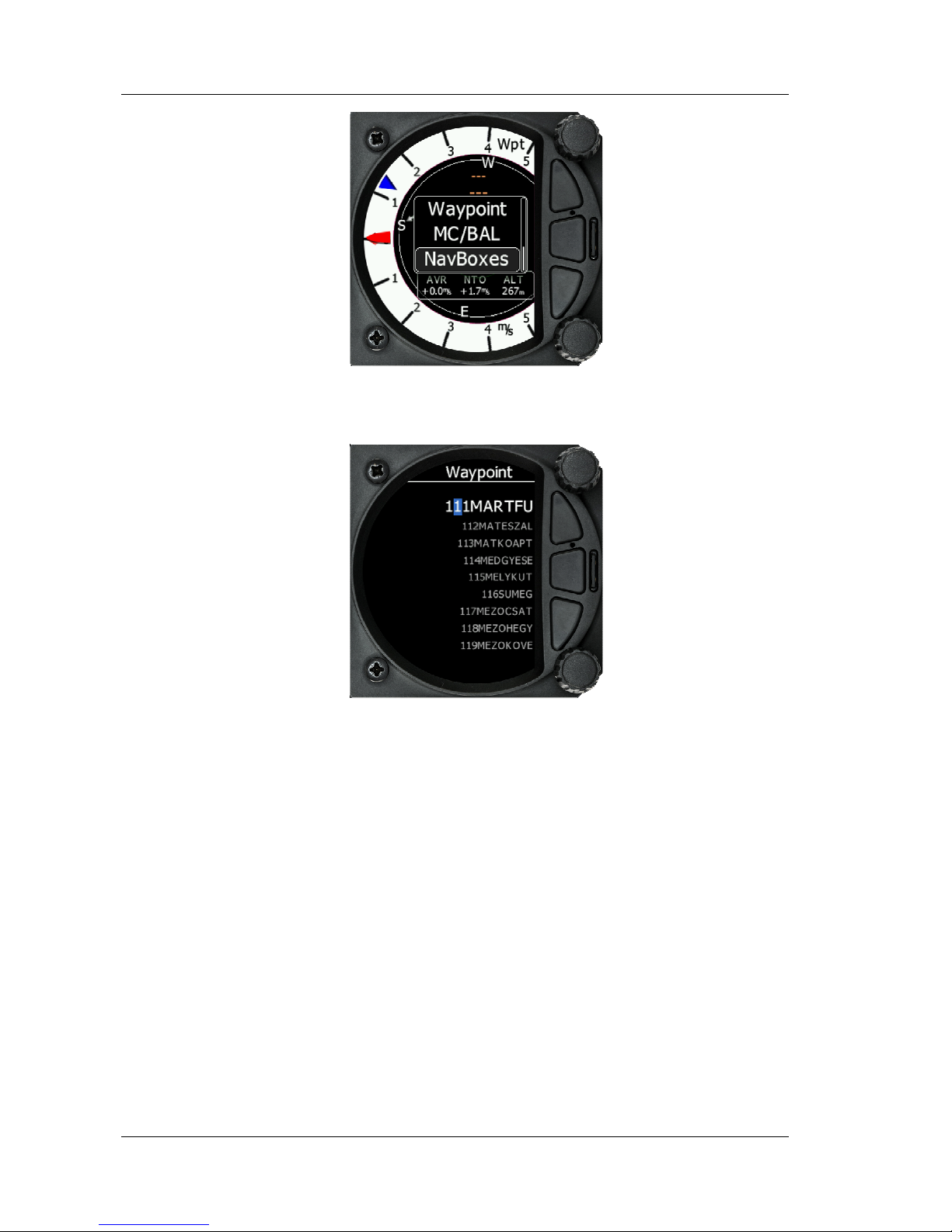
5.3.1.1 Navboxes Option
Using the Quick access menu and select Navboxes allows you to move the position
of the three Navboxes from the bottom of the screen to the right hand side of the
screen by rotating the bottom rotary knob.
Page 19

S80 Version 4.92 November 2014
Page 19 of 61
Pressing the Enter button salves the position setting and scrolls down a page.
5.3.1.2 Editing Navboxes
Selecting the Navboxes option and then pressing the bottom rotary Knob will allow
you to select one of the three boxes by rotating the bottom rotary knob and a short
press. You can then select the required data for the highlighted Navbox. A short
press of the bottom rotary knob selects the desired setting and returns you to the
Navbox selection. Pressing Enter at any time saves the setting and moves to the
second Waypoint Page
5.3.2 Second Waypoint Page (Numerical Data)
The Waypoint screen has a second page which contains numerical data. Defaults are
Average Vario, Netto, Altitude and True Airspeed. In addition, the central line shows
the status of the Flarm, GPS, Cruise/Climb and battery status. This second page can be
selected by pressing the enter button once. You can return to the Waypoint navigation
page by pressing the Escape button (top button of the three)
Page 20

S80 Version 4.92 November 2014
Page 20 of 61
Vario Needle displays the vario, netto, relative or speed to fly value. The scale can be
chosen in the range of -+/-5 +/-10 or +/-20 (in setup, Vario Parameters). Within the
software the range can be set to m/s, kts, km/h, mph or fpm (in Setup, Units,
Vertical speed)
Upper numbers display Vario Netto, Average Vario
Lower number display True Airspeed and 60 minute task speed
Speed to fly bar symbol is indicating which speed you have to fly relative to the
current MacCready setting, sink rate and speed. One arrow means 10units of speed
faster or slower. Up red arrows mean fly slower and down blue arrows mean fly
faster.
Red diamond symbol can show netto or average vertical speed or g-force.
Blue arrow symbol shows current MacCready value.
Green T symbol represents last thermal average value.
Yellow Bar can show Max and Min values or G meter
The numerical Navboxes can be changed using the quick Access menu with a short
press of the bottom rotary knob followed by selecting Navbox from the menu and a
further short press of the bottom rotary knob. With the first Navbox highlighted with
a yellow boarder you can scroll through the four Navboxes using the bottom rotary
knob. Select the Navbox you wish to change with a short press of the bottom rotary
knob. This will open a list of available Navboxes.
Vario indicator needle
MacCredy setting
Last thermal average
Last thermal average or
G force
Needle type
Wind vector
GPS status
Battery
Lower number
s
Range
/units
Upper number
s
Climb/cruise symbol
Flarm status
Speed to fly
bar
Yellow Bar (Min/Max
vario or Min/Max g-
force
Page 21

S80 Version 4.92 November 2014
Page 21 of 61
Select the required Navbox and then save this with a short press of the bottom rotary
knob. Repeat the process for any other Navbox that needs to be changed.
5.3.3 Third Waypoint Page (AHRS)
The Waypoint screen has a third page which displays the AHRS (if this feature has
been enabled See more in Ch.8.5.4)
Pitch offset can be adjusted with lower rotaty knob.
5.4 Task Screen
The task screen can display a navigation page including airspace and a task. By
rotating the bottom rotary knob, you can change the range of the display from 1KM to
100Km
Page 22

S80 Version 4.92 November 2014
Page 22 of 61
5.4.1 Quick access menu
A short press of the bottom rotary knob activates the quick access menu. In addition
to MacCready, Ballast and Bugs you can Start, or Edit a task. If the Task is started you
can restart or go to the next waypoint. You can also change the Navboxes through this
menu.
• Selecting start and a short press of the bottom rotary knob will start a task.
• Selecting restart and a short press of the bottom rotary knob will restart the
task.
• Selecting next and a short press of the bottom rotary knob will advance the
task to the next waypoint in the task.
• Selecting edit task with a short press of the bottom rotary knob will enter the
task editing screen. The first time you edit a task it will be blank. A short press
of the bottom rotary knob will open another menu with the option to Insert,
Edit, Delete or Zone. Selecting Insert will allow you to enter a waypoint from
the list as a start point. Rotating the bottom rotary knob will scroll through the
waypoints in alphabetical order. Pressing the Enter button will select the first
letter and move the cursor to the right for the second letter. The second letter
can be selected by rotating the bottom rotary knob. Repeat the process until
the desired waypoint is displayed. Press the bottom rotary knob once to select
it. Once the start point is selected, rotate the bottom rotary knob clockwise one
Page 23

S80 Version 4.92 November 2014
Page 23 of 61
click to display the second turn point. Edit the second turn point as above.
Repeat for all the points in the task. When you have completed editing the
task, press the page (middle) button to save the task and return to the Task
navigation page.
You can also change the Observation zone from the defaults for each Waypoint. To do
this, select the waypoint in the task and then press the bottom rotary knob. The quick
access menu allows you to insert, edit, delete or change the zone for the Waypoint. If
you select Zone, you can modify the zone for that specific waypoint only.
5.4.2 Second Task Page (Numerical Data)
The Task screen has a second page which contains numerical data. Defaults are
Average Vario, Netto, Altitude and True Airspeed. In addition, the central line shows
the status of the Flarm, GPS, Cruise/Climb and battery status. This second page can be
selected by pressing the enter button once. You can return to the task navigation page
by pressing the Escape button (top button of the three)
Page 24

S80 Version 4.92 November 2014
Page 24 of 61
The navigation boxes in this second task page can be changed using the quick access
menu and selecting Navbox. You can make changes to the Navboxes as described in
Error! Reference source not found.
5.4.3 Third Task Page (AHRS)
The Waypoint screen has a third page which displays the AHRS (if this feature has
been enabled)
5.5 Setup Screen
The setup screen allows you to change the configuration and base settings for the S80
Vario.
Page 25

S80 Version 4.92 November 2014
Page 25 of 61
Following items are listed in the setup menu:
• QNH &RES
• Vario Param.
• Display
• Graphics
• Sounds
• Warnings
• Obs. Zones
• Units
• Hardware
• Files
• Polar & Glider
• Password
• About
You can scroll up and down the list of settings by rotating the bottom rotary knob and
select a setting to change with a short press of the bottom rotary knob.
Some of the Options have sub menus and these are selected in the same way.
5.5.1 QNH & RES
Turn the bottom rotary knob to select the required entry field. Press the bottom rotary knob
to select it and start editing the value. A further shot press will enter the value.
Page 26

S80 Version 4.92 November 2014
Page 26 of 61
5.5.1.1 QNH
This feature may be used to offset the altitude datum as the result of pressure changes
during the flight. Since changing the QNH influences the indicated altitude, care should be
taken when changing the value as an incorrect setting could upset the final glide calculation.
5.5.1.2 Safety Altitude
This setting is the altitude reserve or safety altitude and is the height that the instrument
adds to the final glide altitude required so the glider arrives over the final glide destination at
the selected safety altitude. Once the safety altitude has been specified, the pilot has to
keep the final glide indicator on 0 to arrive at the safety altitude.
Page 27

S80 Version 4.92 November 2014
Page 27 of 61
5.5.2 Vario Param.
5.5.2.1 Vario needle filter
Sets a time constant of the vario needle. The value can be adjusted between 0.1 and 5 s
with step 1.0 s or 0.1 s. Default value is 1.5 s.
5.5.2.2 Vario sound filter
Sets a time constant of vario sound. The value can be adjusted between 0.1 and 5 s with
step 1.0 s or 0.1 s. Default value is 1.5 s.
5.5.2.3 Netto filter
Sets a time constant of the Vario Netto needle. The value can be adjusted between 0.1
and 5 s with step 1.0 s or 0.1 s. Default value is 1.5 s.
5.5.2.4 Relative filter
Sets a time constant of the Vario Relative needle. The value can be adjusted between 0.1
and 5 s with step 1.0 s or 0.1 s. Default value is 1.5 s.
5.5.2.5 SC filter
Sets a time constant of the SpeedToFly needle. The value can be adjusted between 0.1
and 5 s with step 1.0 s or 0.1 s. Default value is 1.5 s.
5.5.2.6 Smart Filter
The Smart Filter allows additional filtering of the vertical speed. It defines the difference
between increasing vertical speed versus decreasing vertical speed. (E.g. If the vario filter is
set to 1s and the Smart Filter set to 4s, the filtering for increasing vario would be 1s and for
decreasing vario would be 2s. This will produce an effect similar to a Sage Variometer.)
FILTER
0.5 to 5
Smart Vario
FILTER
1 to 8 or OFF
RAW
VARIO
FILTERED
VARIO
VARIO
INDICATOR
Page 28

S80 Version 4.92 November 2014
Page 28 of 61
5.5.2.7 Needle range
Sets full scale range of the vario (2.5 m/s, 5 m/s or 10 m/s). Default value is 5 m/s (10 kts).
5.5.2.8 Dead Band (SC tab)
Defines the width of the audio dead band in speed to fly mode. Default value is ±1 m/s.
5.5.2.9 Auto SC
Defines the conditions when the instrument will switch automatically between vario and
speed to fly mode.
• OFF: Switching is exclusively by an external switch connected to the S80.
• GPS: When the GPS detects that the glider is circling an automatic change over to vario
will happen after approximately 10 seconds. Detection of straight flight will cause a
changeover to speed command.
• TAS: When the TAS exceeds a pre-set value. The TAS at which switching occurs can be
selected in 5 km/h steps from 100 up to 160 km/h (or the equivalent in knots or mph).
• G-meter – for switching between cruise and climb mode based on the G measured by
the inertial system. When glider will start circling, S80 will automatically switch from
cruise to climb mode.
The external switch wired to the LXNAV S80 has absolute priority and will override
all other switching methods.
5.5.2.10
Vario Average Time
Defines the integration period for the average vario in seconds. The default is 20 seconds.
5.5.2.11
Netto Average Time
Defines the integration period for the average netto vario in seconds. The default is 10
seconds.
5.5.2.12
Temperature Offset
The LXNAV S80 is supplied with an external outside air temperature (OAT) sensor. With the
offset setting it will correct static errors of temperature measurement.
5.5.2.13
Inertial assisted vario
With the LXNAV S80, it is possible to adjust the influence of g-force on the vario. This
influence is very small and can be set to Off or between 0 and 4.
Page 29

S80 Version 4.92 November 2014
Page 29 of 61
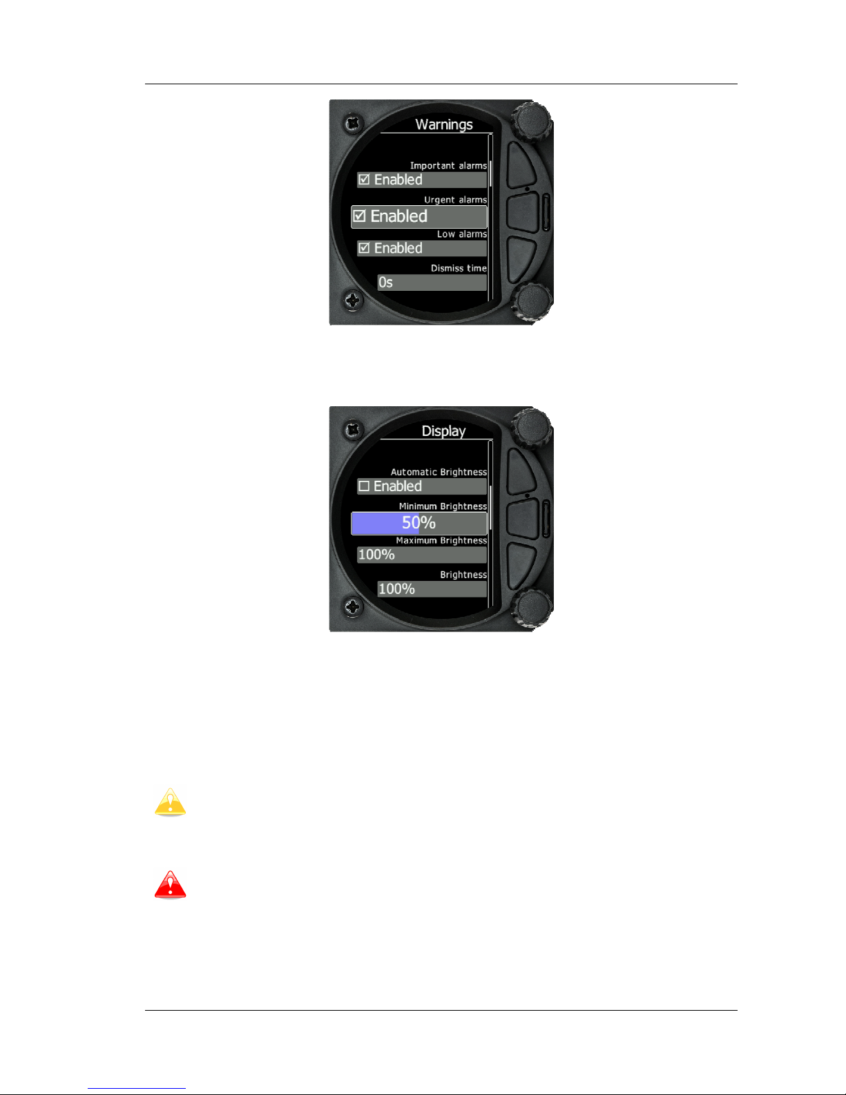
5.5.3 Display
5.5.3.1 Automatic Brightness
If the Automatic Brightness is checked then the brightmess will be automaticaly
adjusted between the minimum and maximum parameters set. If the Automatic
Brightness is Unchecked then the brightness is controled by the brightness setting
5.5.3.2 Minimum Brightness
Use this slider to adjust the minimum brightness for the Automatic Brightness
option.
5.5.3.3 Maxximum Brightness
Use this slider to adjust the maximumm brightness for the Automatic Brightness
option
5.5.3.4 Brightness
• With the Automatic Brightness unchecked, you can set the brightness manually with this
slider.
5.5.4 Graphics
The graphics option has a sub menu for Flarm and for Airspace and Tasks
Page 30

S80 Version 4.92 November 2014
Page 30 of 61
5.5.4.1 Graphics – Flarm
5.5.4.1.1 Colours can be set for the following:
Glider Above Colour
Glider Below Colour
Glider Near Colour
Selected target Colour
5.5.4.1.2 Label Text
This option can be set to None, Flarm ID, Climb rate, Relative vertical
Page 31

S80 Version 4.92 November 2014
Page 31 of 61
5.5.4.1.3 Active Timeout
Adjusts the time a glider symbol remains on the map after it has last been seen by the
Flarm.
5.5.4.1.4 Inactive Timeout
Adjusts the time of inactive gliders on the Flarm target list. Inactive gliders are gliders,
where the Flarm signal has been lost after Active timeout. The targets became inactive
and remain only on the Flarm target list for this time.
5.5.4.1.5 Draw Line to selected Target
Checkbox to enable or disable a line drawn to a selected Flarm target or not.
5.5.4.1.6 Draw History
Select if a trail is drawn behind Flarm targets to show where the targets have been
5.5.4.1.7 Plane icon size
To adjust the pixel size of Flarm targets.
5.5.4.2 Graphics – Airsp. & Tsk.
In this dialogue you can define the airspace map presentation. Check the Show airspace
item to enable airspace displays in navigational pages. If this item is unchecked no airspace
will be displayed.
If the Show inactive zones option is checked then airspace zones with proximity warning
switched off will be shown. Use Show only airspace below to eliminate airspace which is
going to be too high for the day. For example, if the forecasted cloud base is to be 1500 m,
set this value to 1600 m and your screen will be much more readable.
Page 32
S80 Version 4.92 November 2014
Page 32 of 61
For the task settings, you can turn on the display of waypoints with the check box and
change the colour of the task, the line to the next waypoint and the zone colour. In addition,
you can change the transparency of the Observation zone, user messages and the
Navboxes. Zone line width can also be adjusted.
In the airspace type list you can specify how each airspace type is displayed. You should
define each type of airspace zone separately. First choose an airspace type from the list.
You can modify the Transparency of the selected type. Zoom value defines to which zoom
level this type is going to be visible. The Colour and Width items specify how selected
airspace zone will be drawn.
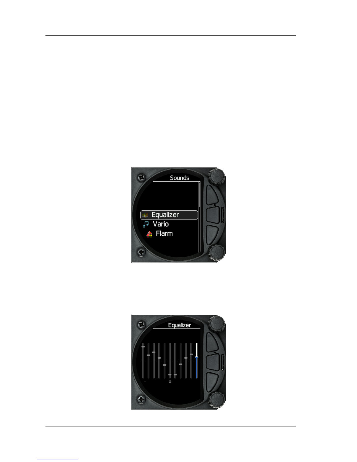
5.5.5 Sounds
The sound option has a sub menu for Equaliser, vario and Flarm
5.5.5.1 Equalizer Option
With the bottom rotary knob you can adjust the volume for each frequency.
Settings are stored when you exit the screen
Page 33

S80 Version 4.92 November 2014
Page 33 of 61
5.5.5.2 Vario Sounds
Vario Volume default setting can be set with this slider.
The volume for Vario, Flarm and Speech can also be adjusted directly with the top
rotary knob whilst in the Flarm, Waypoint and Task screens
Vario Audio mode
Vario audio mode has the following options:
• Linear positive: sound is interrupted with silence every few milliseconds when the
needle is positive; on negative side sound is linear (not interrupted).
• Linear negative: inverse function to Linear positive.
• Linear: sound is linear and non-interrupted in full scale range.
• Digital positive: similar to Linear positive, except frequency is not changing linearly
but with larger steps.
• Digital negative: inverse function to Digital positive.
• Linear positive only: sound is present only at positive values, for negative values there
is silence.
• Digital positive only: similar function to Linear positive only, except the sound is
similar to the digital tone.
SC Audio mode
SC audio mode has five modes:
• Netto Speed: Sound follows netto value.
• SC Mixed: for positive relative values the sound represents relative; for negative
• Speed to Fly: sound is linear and non-interrupted in full scale range.
• relative values the sound represents SC (for that setting it is recommended to set SC
needle to relative). Dead band is active only for negative values.
• SC negative: inverse function to SC positive.
• SC positive: sound is interrupted with silence every few milliseconds when the needle is
positive; on negative side sound is linear (not interrupted).
Audio frequencies
Page 34

S80 Version 4.92 November 2014
Page 34 of 61
• Freq at 0% defines the tone frequency at 0 m/s.
• Freq at +100% defines the tone frequency at full + deflection.
• Freq at -100% defines the tone frequency at full – deflection.
Equalization preset
We have three options: default LXNAV speaker, flat setting or user defined.
Beeps requested from PDA
If a PDA is connectedc to the S80 the PDA is able to send a beep command to the S80, if
that feature is enabled, S80 will beep on PDA request.
Thermal Assistant
Is a system generated sound which is different from other vario sounds. This sound helps
the pilot in a thermal by interupting other varios sounds a few secodns before the therml
reaches its maximum lift. The pilot can set how many seconds before thermal maximum or
disable the feature.
Speech Volume
With the Speech volume slider the volume of voice warnings can be changed.
The volume for Vario, Flarm and Speech can also be adjusted directly with the top
rotary knob whilst in the Flarm, Waypoint and Task screens
5.5.5.3 Flarm Sounds
Flarm Volume: can be adjusted with the slider
Flarm Low Alarm: For distant Flarm targets the S80 can give a short or long message,
just a beep or be turned off.
Page 35

S80 Version 4.92 November 2014
Page 35 of 61
Flarm Important Alarm: For close Flarm targets the S80 can give a short or long
message, just a beep or be turned off.
Flarm Urgent Alarm: For very close Flarm targets the S80 can give a short or long
message, just a beep or be turned off.
The volume for Vario, Flarm and Speech can also be adjusted directly with the top
rotary knob whilst in the Flarm, Waypoint and Task screens
5.5.6 Warnings
Warnings can be enabled or disabled in this section.
The warnings dismiss time can be set from 0 to 120 seconds
Dismiss while circling: This dismisses Flarm alarms whilst circling for Flarm targets in
the same thermal. Flarm warning for urgent alerts over ride this.
Altitude Alarm: can be set in meters/feet
Altitude Alarm time out: can be set from 10 to 500 seconds
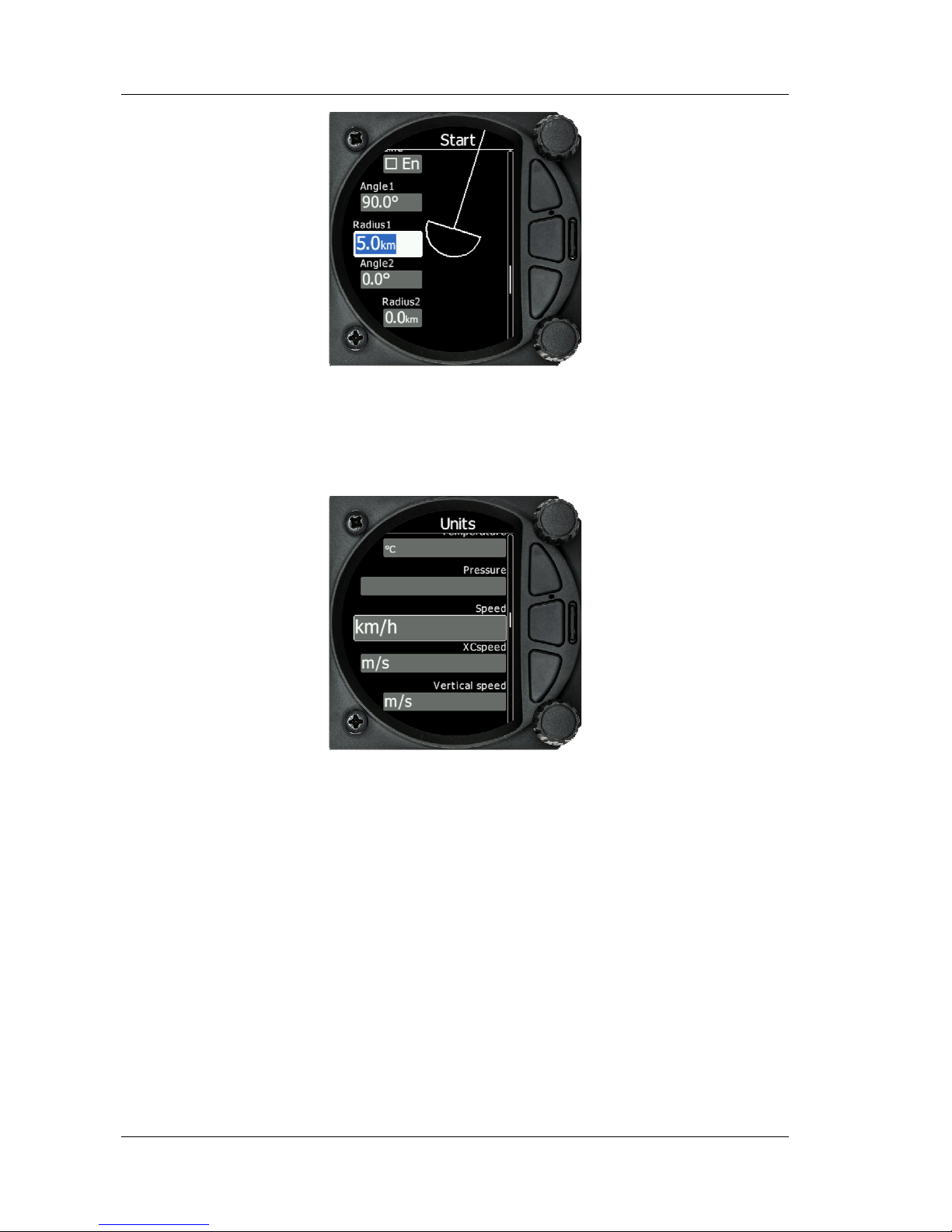
5.5.7 Obs. Zones
The default Observation Zones can be configured in this section for all tasks.
Page 36

S80 Version 4.92 November 2014
Page 36 of 61
The start, turn point and Finish zone can be configured separately although the setup
is very similar.
The Start and Finish zone do not have the option of the AAT check box or Auto next.
Direction: Options include Start, Previous, Next, Symmetrical or Fixed angle
Angle 12: is greyed out unless fixed angle is specified in Direction
Line Check Box; typically used for start and Finish. If line is checked then Angel 1,
Angle 2 and Radius 2 are greyed out
Angle 1: Sets the angle of the Turn Point Zone
Radius 1: Sets the radius of the Turn Point Zone
Angle 2: Sets angle 2 for complex Turn Points and Assigned Area Tasks
Radius 2: Sets the radius for complex Turn Points and Assigned area Tasks
AAT Check Box: when checked, the S80 considers the area created within the zone
as an Assigned area
Auto Next: Typically used in racing tasks, will set the navigation of the S80 to the
next turn point when a single point is made within the Turn Point Zone.
5.5.8 Units
Use this menu to specify units, UTC time offset and type of ballast input.
Page 37

S80 Version 4.92 November 2014
Page 37 of 61
Language: Available in later versions
Distance: Units available; Miles, Nautical Miles, Kilometres,
Altitude: Units available Feet, meters
Temperature: Units available; Degrease Centigrade or degrease Fahrenheit
Pressure: Units available; Inches of Mercury, mm of mercury, mbar,
Speed: Units available; fpm, m/s, mph, kts, km/h
XC Speed: Units available; fpm, m/s, mph, kts, km/h
Vertical Speed: Units available; fpm, m/s, mph, kts, km/h
Wind: Units available; fpm, m/s, mph, kts, km/h
Weight: Lbs or Kg
Load: Lb/ft2 or Kg/m2
Longitude/Latitude: DD.ddddd, DDMM.mmmmm’, DDMM’SS.ss”, DD.dddd, DDMM.mmm’,
DDMM’SS”
UTC Offset: in half or whole hours plus or minus Zulu
Ballast: weight, Load, overload
5.5.9 Hardware
The hardware setup has a sub menu for Vario, Indicator, comms. and Battery
Vario Setup
Page 38
S80 Version 4.92 November 2014
Page 38 of 61
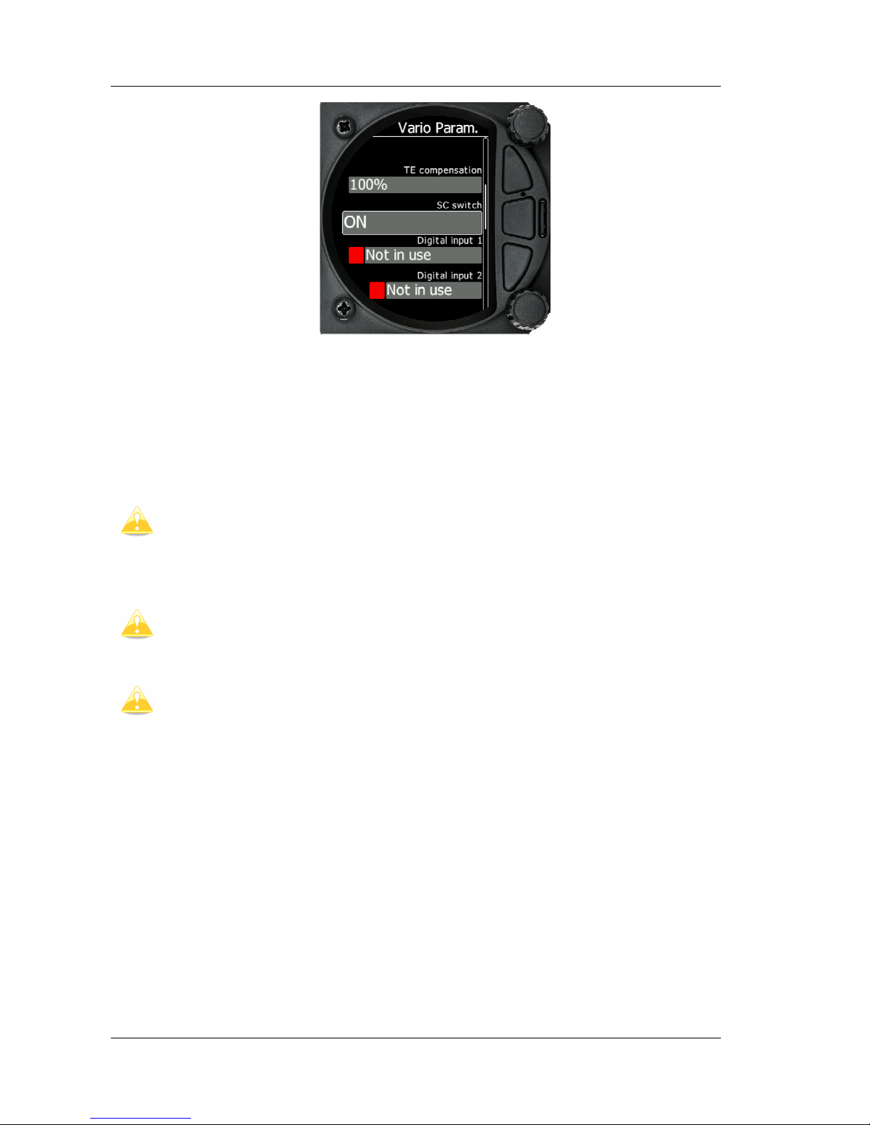
5.5.9.1 TE compensation
The LXNAV S80 offers two methods of vario Electronic Total Energy Compensation:
• TE Pitot tube
• Electronic TE compensation
It is important to note that the method of TE compensation is set up when the
instrument is installed by virtue of the pneumatic connections made to the TE and
static ports. Changing the compensation type in the setup screen below WILL
NOT change the method of compensation - the pneumatic plumbing has to be
changed first.
If the TE pitot tube has been connected TE compensation should be set to 0%.
There is no further adjustment of TE compensation possible. Quality of the TE
tube is the one and only factor.
If the electronic TE option has been installed TE compensation should be set to
100%.
The electronic TE compensation can be fine-tuned during flight using the following
procedure: it is essential that this is only done in smooth air; it is not possible to tune the
TE accurately in turbulent air.
Set TE compensation to 100%. Accelerate up to approximately 160 km/h (75 kts) and keep
the speed stable for a few seconds. Gently reduce the speed to 80 km/h (45 kts). Observe
the vario indicator during the manoeuvre. At 160 km/h the vario will indicate about –2 m/s
(-4 kts). During the speed reduction the vario should move towards zero and should never
exceed zero (slightly positive indications are acceptable). If the vario shows a climb the
compensation is too low; increase the TE%; and vice versa. Try another “zoom” to assess
the change and make further adjustments if necessary.
Electronic TE compensation is only effective when the Pitot tube and static sources are colocated and the pneumatic lines to the instrument are approximately the same length. The
best sensor to use is the combined pitot/static Prandtl tube. If problems are experienced
with the electronic TE compensation the most likely cause is the glider's static source. The
static source can be checked by plumbing the pneumatic tubes for electronic compensation
Page 39

S80 Version 4.92 November 2014
Page 39 of 61
and then setting the TE: to 0%. In still air accelerate to approximately 160 km/h and slowly
reduce the speed. Observe the vario indicator. If the static source is good the vario should
immediately start to move to show a climb. If the needle firstly shows increased sink and
then moves to a climb, the static source of the glider is unsuitable and there is no way to
provide successful TE compensation electronically. The use of a dedicated and accurate finmounted pitot/static source such as a Prandtl tube might help.
5.5.9.2 SC switch
The LXNAV S80 has an input for an external speed command switch. Using the external
switch it is possible to switch between SC and Vario manually. Setting the SC switch to ON
means that closing the switch will cause the instrument to enter SC mode and setting SC
switch to OFF means that closing the switch will select Vario mode. There is a third option
by setting SC INPUT to TASTER and connecting a push button to the input; each key press
will toggle between SC and Vario (mandatory setting for LX Remote).
There is another input called VARIO PRIORITY. When this input is activated by
grounding the appropriate wire the unit will change over to Vario immediately.
This input wire is set open (not grounded) as a factory default on delivery.
5.5.9.3 Digital Input 1 and 2
The LXNAV S80 has two external digital inputs which can be set to indicate gear,
airbrakes and water open or closed.
Input pins are available on rear DB15 connector, but they are not wired.
5.5.10 Indicator setup
Vario Needle: Can be set to Relative, Netto, Speed to Fly or Vario
SC needle: Can be set to Relative, Netto, Speed to Fly or Vario
Yellow Bar: Can be set to G-meter, Min/Max vario or no bar
Red Diamond: Can be set to G-meter, Netto, Average vario, or No diamond
MacCready: Can be enabled or disabled
Thermal: can be enabled or disabled
Page 40

S80 Version 4.92 November 2014
Page 40 of 61
STF of Speed To Fly: Can be enabled or disabled
Flarm: Can be enabled or disabled for warnings on the Vario Indicator
5.5.11 Comms. Setup
Used to configure the two ports on the back of the S80 for connection to a GPS/Flarm
source and to a PDA
Each port can be configured separately. If your PDA device does not support automatic
switch to DIRECT LINK between GPS and PDA port, here is manual GPS-PDA link menu.
When autobaudrate is enabled, the LXNAV S80 will automatically search on all speeds to
receive valid data. When the S80 receives a valid NMEA sentence it will lock on that baudrate
and stop searching. In case that communication is lost LXNAV S80 will start again searching
on all baudrates.
Baudrate on PDA must not be lower than the setting on GPS port
To get better performance of LXNAV S80 it is recommended that both baudrates
be set as high as possible.
NMEA output on PDA port can be enabled or disabled. If you are not using a PDA port, this
setting should be disabled.
Bluetooth is not supported in this version
5.5.12 Battery Chemistry Setup
A new feature within the S80 is the ability to configure your battery chemistry and
battery warnings. Batteries used in gliders today are not just the old style lead acid
battery but also Lithium Iron and Lithium Iron Phosphate. Each battery type has a
different power delivery curve and it is now possible to configure the Low and High
Battery warnings
Page 41

S80 Version 4.92 November 2014
Page 41 of 61
Select Battery from List gives you a drop down list with the suggested battery settings
for Full Voltage, Low Battery Voltage and Empty Voltage as pre-sets. Selecting one of
these will set the values in the following boxes.
Alternatively you can manually change the Full Voltage, Low Battery Voltage and
Empty Voltage if your battery type is not listed.
5.5.13 Files
The Files menu allows you to upload or select Waypoint, Airspace and Flarm Net files.
Page 42

S80 Version 4.92 November 2014
Page 42 of 61
5.5.13.1
Waypoints File
Selecting the Waypoints option opens a list of .cup files available on the SD card or in
the internal memory. Selecting a file loads this file for use.
Please note that only one Turn Point file can be loaded at any one time.
5.5.13.2
Airspace File
Selecting the Airspace option opens a list of .cub files available on the SD card or in
the internal memory.
Page 43

S80 Version 4.92 November 2014
Page 43 of 61
Selecting a file loads this file for use.
Please note that only one Airspace file can be loaded at any one time.
5.5.13.3
Flarmnet File
Selecting the Flarmnet option opens a list of .fln files available on the SD card or in the
internal memory. Selecting a file loads this file for use.
Page 44

S80 Version 4.92 November 2014
Page 44 of 61
Please note that only one Flarmnet file can be loaded at any one time.
5.5.14 Polar and Glider
The Polar and Glider section allows you to load and edit a set of parameters for your
gliders Polar. You can select from a pre-defined list of nearly every common Glider or
make your own Polar.
Select Glider from List: Presents you with an alphabetical list of all the common gliders
and associated Polar data. All glider data will be copied from the chosen polar. Then check
the best glide ratio and minimum sink rate, to see if the polar data matches the glider
performance, you may look in MacCready setting menu.
Page 45

S80 Version 4.92 November 2014
Page 45 of 61
You can modify the polar by changing coefficients a, b and c. A polar is defined as a
quadratic equation with the parameters a, b, and c. Use the SeeYou program (Tools->Polar)
to calculate coefficients a, b and c for a given glider’s polar. The program requires three sink
points entered at selected speeds (e.g.: 100 km/h, 130 km/h, and 150 km/h). The program
will calculate the values of a, b and c, which should be noted and entered into the LXNAV
S80.
Class: Options for Touring, Ultralight, World, Doubleseater, Club, 18-meter, 15-meter,
Open, Standard, and Unknown are available.
a, b, c: Options can be adjusted or entered for a non-listed glider.
Stall speed is used to generate stall warnings which are available with integrated Voice
module.
Reference load (wing loading) value represents the value at which the polar was
measured.
Reference weight corresponds to the weight value at which the polar was measured.
Maximum takeoff .weight is the maximum take-off weight allowed for the glider. It is
not used in the calculation; it is just a reminder to the pilot of the maximum take-off weight.
Empty weight is weight of the glider without the pilot and ballast.
Empty glider weight is a weight of empty glider. This number can be found in a glider
book.
Pilot weight is the weight of the pilot with parachute and baggage.
Co Pilot Weight is the weight of the co-pilot with parachute and baggage.
weightgliderMinimum
ballastWaterweightPilotweightgliderEmpty
overload
..
....
+
+
=
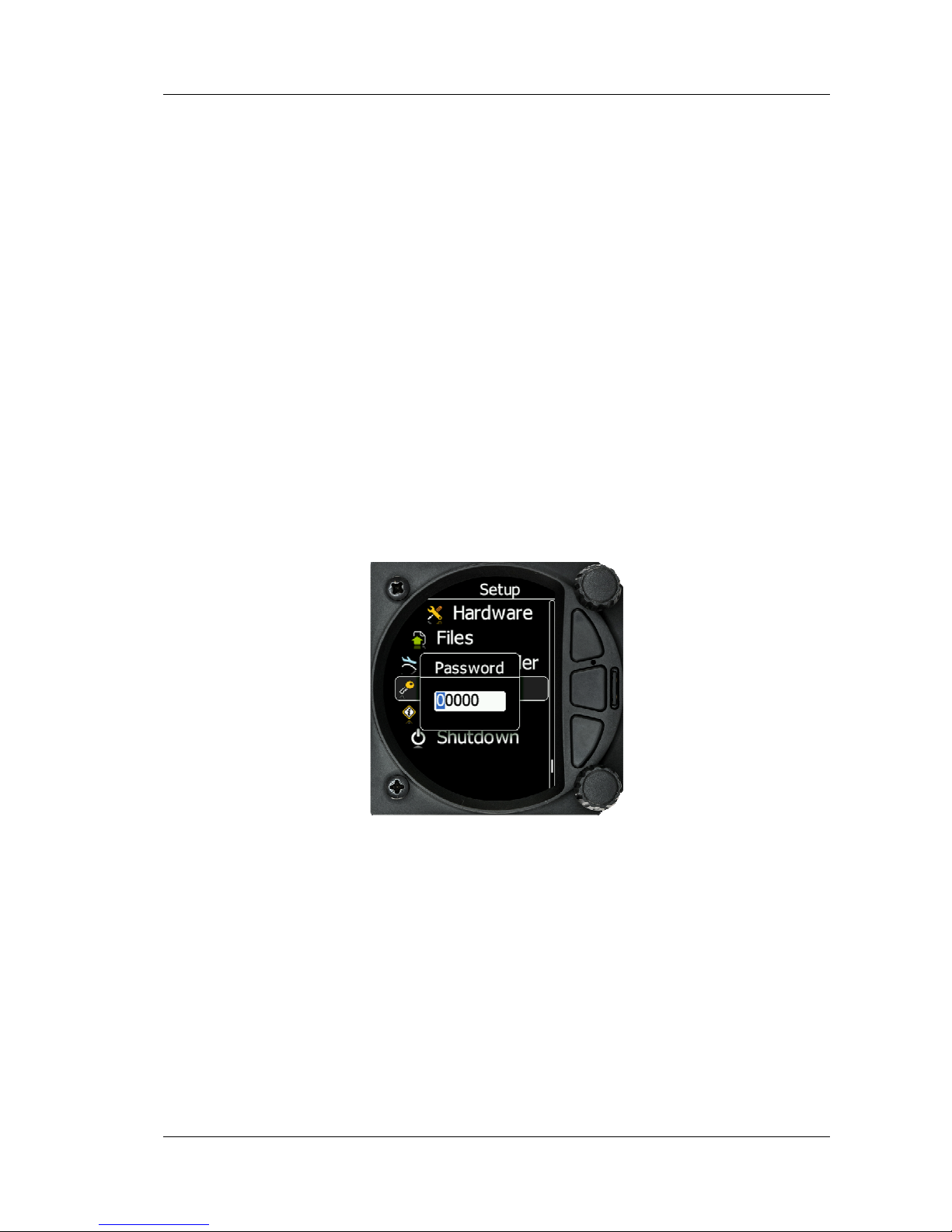
5.5.15 Password
There are several system passwords which run specific procedures as listed below:
Page 46
S80 Version 4.92 November 2014
Page 46 of 61
5.5.15.1
List of Password functions
DEBUG_INFORMATION_PASSWORD 90000
RESET_TO_FACTORY_DEFAULT_PASSWORD 00666
UPDATE_DEVICES_PASSWORD 89891
ENTER_NEW_LICENSE 30000
5.5.16 About
In the about page, information about the display platform and the vario platform can be
found:
Display platform: Application version, serial No, Hardware version,
Vario platform:, Application version, serial No, Hardware version
Page 47

S80 Version 4.92 November 2014
Page 47 of 61
6 Variometer and Altimeter
All signals from the pneumatic sensors (altitude, speed) are derived from high quality
pressure sensors which mean that no flask is necessary. The vario signal is derived from the
altitude signal. All signals are temperature and altitude compensated. The colour display
show the vario information as well as many other parameters.
The display is user configurable. The Variometer can be configured to show:
• Range 5, 10 and 2.5 m/s or 10, 20 and 5 kts.
• Time constants 0.1 s to 5 s, in addition there are 4 settings for electronic processing
for the vario signal.
• Netto shows the air mass lift and sink.
• Relative shows the lift or sink that would be achieved if the glider was circling at the
thermaling speed.
There are two ways by which the vario indications can be corrected for total energy.
Electronic TE compensation based on speed changes with time and pneumatic compensation
with a TE probe. The quality of the TE compensation depends entirely on the location, size
and dimension of the TE tube. The installation must be leak-proof.
If an electronic TE compensation is selected the TE (Pst) port should be connected
to a good static pressure source. If pneumatic compensation is selected the TE
(Pst) port should be connected to the TE probe.
6.1 Altimeter
The altimeter of the LXNAV S80 is temperature compensated from -20ºC up to + 60ºC. The
altimeter is calibrated up to 20000 m.
6.2 Speed Command
Speed command flying based on the MacCready theory is a very useful tool to optimise
cross-country speed. There are many visual indicators (see Error! Reference source not
found.). When the instrument changes to speed command mode the audio will change and
become a director informing the pilot whether he is flying too fast or too slow. In order to
reduce confusion between vario and speed command audio some special features are
incorporated
• Continuous audio signal in + possible (other kinds of signals can be chosen, see
setup).
• No audio at correct speed (dead band).
TE (Pst)
LXNAV S80
Electronic TE compenstaion
Compensation with TEprobe
Page 48

S80 Version 4.92 November 2014
Page 48 of 61
7 Flying with the LXNAV S80
To get the best out of the LXNAV S80 it is important that some preparation is done prior to
take-off. Trying to configure the instrument or set a task while flying is very hazardous
especially in a competition. Pre-flight preparation will ensure that the flight will be both safe
and enjoyable.
7.1 On the Ground
7.1.1 Power on Procedure
Press any of the rotary or push buttons to start the LXNAV S80. The LXNAV S80 welcome
screen will appear. The first screen shows the version of the boot loader, firmware,
hardware and serial number. The boot procedure normally takes a few seconds. When
completed, the Set Elevation dialogue is shown.
7.1.2 Set Elevation and QNH
This setting is crucial for final glide calculation: therefore please pay careful attention to it.
The instrument will offer elevation over standard pressure level QNE. Use the knob to finetune the elevation.
The QNH should be changed only when airfield elevation and QNH pressure are given. This
might happen in some competitions.
In all other cases the elevation should always match QNH pressure.
The Set Elevation dialogues are not shown if the LXNAV S80 is switched off and on
during flight.
Page 49

S80 Version 4.92 November 2014
Page 49 of 61
7.1.3 Pre-flight Check
After elevation setup the LXNAV S80 will switch to the Info screen for normal operation
mode.
It is recommended that you scroll to the Flarm, Waypoint or Task Screen and set the
MacCready, ballast and bugs settings to match the current glider configuration.
When you are in either, the Flarm, Waypoint or Task screen, Press the bottom rotary button.
The dialogue for MacCready, Ballast and Bugs will appear.
Use the bottom rotary knob to modify the MacCready setting.Error! Reference source not
found.
It is also highly recommended to check the safety altitude setting. Refer to Error!
Reference source not found. to find out how to define the safety altitude.
7.2 Airborne
7.2.1 Final glide calculation
Final glide is a function calculated from the target distance, target elevation, altitude, wind
component, MC setting and Bug setting. The S80 will have enough information to calculate
this automatically as long as a GPS source is attached and the target to navigate to is set in
Waypoint or Task screen.
Page 50

S80 Version 4.92 November 2014
Page 50 of 61
8 Installation
The LXNAV S80 requires a standard 80 mm cut-out.
Three pressure connectors are fitted to the back of the S80. A label shows their functions.
• P
static
means static pressure connector.
• P
total
means pitot or total pressure connector.
• TE means total energy TE pressure connector.
If the unit is to be configured for electronic TE compensation the connections are as follows:
• P
static
Static
• P
total
Pitot or Total pressure
• TE/P
static
Static
If the unit is to be configured for pneumatic TE compensation using a TE tube, then the
connections are:
• TE/P
static
TE tube
• P
static
Static
• P
total
Pitot or Total pressure
If the P
total
and Static are connected the wrong way around there will be no
integrator (average climb) and speed to fly indication during the flight.
Page 51

S80 Version 4.92 November 2014
Page 51 of 61
The LXNAV S80 is connected to 12 Volt power via the 15-pin SUB-D connector. Optionally
LXNAV S80D can be connected via the CAN bus and the connectors are labelled with “CAN”
at each end.
Instrument has no internal fuse. 3A external fuse is required! Power supply
cables should use a minimum of 0.5 mm² wires.
8.1 Installing the LXNAV S80
The LXNAV S80 vario should be mounted in a standard 80 mm hole.
Remove the two rotary knob caps with a knife or flat screw driver, then hold each knob and
unscrew it.
Remove the remaining two screws and the two M6 threaded nuts. Install S80 into the panel,
screw back all screws, nuts and knobs. Make sure that between the knobs and the panel
there is some space, to push button.
Be sure that LXNAV S80 is placed far enough from compass.
8.2 Connecting LXNAV S80
LXNAV S80 is connected to 12V DC power supply. Red wire goes to + positive and blue wire
goes to – ground. If you don’t use S80D (second seat unit) The Can connector should be left
terminated with a CAN terminator. The SC cable is used for external switch, for switching
between climb and cruise mode.
8.3 Cutout of S80
Page 52

S80 Version 4.92 November 2014
Page 52 of 61
Length of screw is limited to max 4mm!
8.4 Available cables for GPS and PDA ports
GPS port
Device
Cable code
Nano power
CC-NP-LX
(
RX/TX are crossed)
Generic RS232
with female DB9
V7-
GPS-232
Flight recorders, FLARMs
with
standard 6p IGC
connector RJ11 type, Red Box, Colibri, Colibri2, VL
V7-GPS-IGC
Power flarm (RJ45), K6 mux
V7-
GPS-PF
PDA port
Device
Cable code
OUDIE
CC-NP-
OUDIE1
Generic RS232
with female DB9
CC-NP-
232
IPAQ 310/314
CC-NP-
IPAQ310
IPAQ 3
8
/39xx
/47xx
CC-NP-38
MiniMap
CC-NP-LX
PDA and GPS are not designed in accordance with IGC standard. It can be used
only with dedicated cable. Do not plug unknown cable to it as it may damage
LXNAV S80 unit.
8.5 Installation of options
The LXNAV S80 can be optionally connected to a 2nd seat repeater unit LXNAV S80D, remote
stick, magnetic compass and AHRS option.
Page 53

S80 Version 4.92 November 2014
Page 53 of 61
8.5.1 S80D option (S80 repeater)
In two-seat gliders it is possible to install the LXNAV S80D rear seat device. The S80D looks
almost identical to the S80. In fact it runs on exactly the same software as on first seat
device.
The basic idea of the two-seat configuration is that both devices work independently from
each other with the possibility of automatically exchanging various pieces of data (volume,
Mc, polar…).
8.5.1.1 Data Exchange
All data is exchanged between front and rear unit. LXNAV S80 also exchanges data with GPS
and PDA. Change of MC, Bal, Bugs, Volume, polar settings,... on PDA, will also influence on
LXNAV S80. The Same will happen also in opposite way.
8.5.1.2 Cable Wiring (LXNAV S80D)
8.5.2 Magnetic compass (Compass -CAN)
Is simply connected to CAN bus, main unit will recognize it. In the moment is not available.
8.5.3 Remote stick (Remote-CAN)
Remote stick is also connected to CAN bus. On S80 is provided special menu to register
remote stick. Device must be registered in case of double seat device, there is possible to
have two remote stick, one registered on front and another on rear device.
350 cm
Reserved for CAN BUS
SUBD9 / female
CAN H
1
6
2
7
3
8
4
9
5
J3
CAN L
CAN GND (SHIELD)
CAN
GND (SHIELD)
12V
LABEL: CAN BUS
1
6
2
7
3
8
4
9
5
J3
Reserved for CAN BUS
SUBD9 / male
LABEL: CAN BUS
CAN
CC-NP-OUDIE
CAN-PDA
CAN
CC-NP-OUDIE
Page 54

S80 Version 4.92 November 2014
Page 54 of 61
8.5.4 AHRS option
To activate AHRS, an activation code must be purchased.
AHRS option can be activated by the following procedure:
- Enter password 30000
- Enter 13-digit license key and confirm
If the code is correct, you will see an AHRS on AHRS page.
8.6 Ports and Wiring
8.6.1 LXNAV S80 ports
Static probe
Total pressure probe
(Pitot)
TE probe or
Static
Audio output
PDA port RJ45 type
GPS port RJ11
type
Main power supply
(V7 wiring)
Page 55

S80 Version 4.92 November 2014
Page 55 of 61
PDA port (RJ45)
1 2 3 4 5 6 7 8
Pin numbers
Pin number Description
1,2 Ground
3 (output) Transmit from LXNAV S80 RS232 (e.g. Computer, IPAQ38/39xx)
4 (input) Receive to LXNAV S80 RS232 (e.g. Computer, IPAQ38/39xx)
5 (output) Transmit from LXNAV S80 LV-TTL (3.3V) (e.g. Oudie, HP302,
HP31x)
6 (input) Receive to LXNAV S80 LV-TTL (3.3V) (e.g. Oudie, HP302, HP31x)
7,8 5V OUTPUT (maximum 1A)
RJ45 plug is NOT designed in accordance with IGC standard. It can be used only
with dedicated cable. Do not plug unknown cable to it as it may damage LXNAV
S80 unit.
GPS port (RJ11)
1 2 3 4 5 6
Pin numbers
Pin number Description
1 (output) 12V DC, to supply GPS
2,3 N.C.
4 (input) Receive to LXNAV S80 RS232 (e.g.NANO power 232)
5 (output) Transmit from LXNAV S80 RS232 (e.g.NANO power 232)
6 Ground
Page 56

S80 Version 4.92 November 2014
Page 56 of 61
Main port
The main port is used to connect the S80 to the main wiring loom.
Audio port
The supplied speaker is connected with a standard 3mm phono jack.
This port is designed to be connected with an 8 ohm speaker supplied with the
S80. Please consult with your dealer, if you want to make a different connection.
8.6.2 LXNAV S80 wiring
SUBD15 Connector / female
S80
1
9
2
10
3
11
4
12
5
13
6
14
7
15
8
SC switch
30 cm
50 cm
OAT
1.5m
LABEL:OAT
LABEL:SC
shield
CAN BUS
SUBD9 / female
CAN H
1
6
2
7
3
8
4
9
5
J3
CAN L
CAN GND
CAN GND
12V
LABEL: CAN BUS
1 2 3
GND
LM335Z
GND SHIELD
GND SHIELD
50 cm
LABEL: +12V DC IN
RED
BLUE
SC
B
A
VP
OAT
CANH
CANL
12V IN
IN1
IN3
IN2
IN0
If a CAN BUS cable is not connected to an LXNAV S80D, the CAN connector must
be terminated with a CAN TERMINATOR!
8.7 Configurations
8.7.1 NANO – S80 – OUDIE
Nano Power
CC-NP-LX
cable
USB cable
NANO
S80
OUDIE
CC-NP-
OUDIE
cable
Page 57

S80 Version 4.92 November 2014
Page 57 of 61
8.7.2 NANO – S80 – MINIMAP
8.7.3 Nano3– S80 – OUDIE
8.7.4 COLIBRI2 – S80 – OUDIE
MINIMAP
Nano Power
CC-NP-LX
USB cable
NANO
S80
CC-NP-LX
cable
USB cable
S80
OUDIE
CC-NP-OUDIE
cable
CC-NP-LX
cable
COLIBRI2
COLIBRI
Power
USB cable
S80
OUDIE
CC-NP-OUDIE
cable
V7-GPS-IGC
cable
Page 58

S80 Version 4.92 November 2014
Page 58 of 61
8.7.5 COLIBRI,VOLKSLOGGER– S80 – OUDIE
8.7.6 Flarm/RedBox– S80 – OUDIE
8.7.7 FlarmMouse - FlarmView -S80 - OUDIE
S80
OUDIE
CC-NP-OUDIE
cable
V7-GPS-IGC
COLIBRI
VolksLogger
S80
OUDIE
CC-NP-OUDIE
cable
V7-GPS-
IGC
cable
FlarmView
cable
Flarm/RedBox
V7 Flarm
Splitter
FlarmView
S80
OUDIE
CC-NP-OUDIE
cable
V7-GPS-IGC
cable
FlarmView
cable
V7 Flarm
Splitter
FlarmView
Page 59

S80 Version 4.92 November 2014
Page 59 of 61
8.7.8 FlarmMouse – S80 – OUDIE
S80
OUDIE
CC-NP-OUDIE
cable
Flarm Mouse
Page 60

S80 Version 4.92 November 2014
Page 60 of 61
9 Firmware Update
Firmware updates for the main display indicator and vario unit can be easily carried out
using the micro SD Card. Please visit our webpage www.lxnav.com and download the
firmware update.
You can also subscribe to a newsletter to receive news about the system automatically.
9.1 Updating LXNAV S80 firmware using micro SD card
Transfer the Firmware update files to the micro SD card and insert it into the S80. You
should receive a message that the SD card has been loaded.
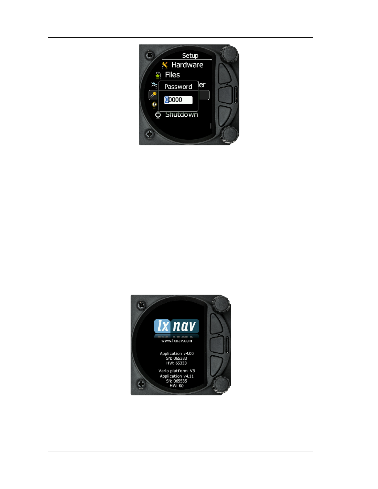
Go to Setup screen and select the password option.
Enter the password 89891, this will bring you to the firmware update menu.
Choose the right firmware for vario part and press update.
To update display part, S80 must be restarted.
Firmware fro vario has name NINB, firmware for display part has name V80C.
Page 61

S80 Version 4.92 November 2014
Page 61 of 61
10 Revision History
October 2014
Initial release
ver 4.9
November 2014
Updated chapters
8.5.1
,
8.5.2
,
8.5.3
 Loading...