

LXNAV LX90 Series, LX80 Series User Manual
LX90xx and
LX80xx
GPS-Navigation System with variometer
Version 5.00
LXNAV d.o.o. • Kidričeva 24a, 3000 Celje, Slovenia • tel +386 592 33 400 fax +386 599 33 522
info@lxnav.com • www.lxnav.com


LX90xx/LX80xx Version 5.0 June 2015
Page 3 of 166
1 Important Notices 8
1.1 Limited Warranty 8
2 Basics 9
2.1 The LX9xx/LX80xx series at a glance 9
2.1.1 Display Unit Features 9
2.1.2 V9 Vario Unit Features 10
2.1.3 V8 Vario Unit Features 11
2.1.4 V80 Vario Unit Features 11
2.1.5 Interfaces 12
2.1.6 Internal Options 12
2.1.7 External Options 12
2.1.8 Simulator 13
2.1.9 Technical Data 14
2.1.9.1 LX9000 System 14
2.1.9.2 LX9050 System 14
2.1.9.3 LX9070 System 14
2.1.9.4 LX8000 14
2.1.9.5 LX8080 15
2.1.10 Weight 15
3 Packing Lists 16
3.1 LX90xx with Flarm Option 16
3.2 LX90xx 16
3.3 LX90xxD 16
3.4 LX80xx with Flarm Option 16
3.5 LX80xx 16
3.6 LX80xxD 17
4 System Description 18
4.1 Rotary Switches and Buttons 18
4.1.1 Landscape orientation 18
4.1.2 Portrait orientation 20
4.1.3 Buttons 20
4.1.3.1 Power Button 20
4.1.4 Rotary Switches (Knobs) 20
4.2 Switching on the Unit 21
4.3 User Input 21
4.3.1 Text Edit Control 22
4.3.2 Masked Text Edit Control 22
4.3.3 Spin Control 23
4.3.4 Selection Control 23
4.3.5 Checkbox and Checkbox List 23
4.3.6 Colour Selector 23
4.3.7 Font Selector 24
4.3.8 Line pattern Selector 24
4.3.9 Pull down menu 25
4.4 Switching off 25
5 Operating Modes 27
5.1 Setup Mode 29
5.1.1 QNH and RES 29
5.1.1.1 QNH* 29
5.1.1.2 Safety Altitude 30
5.1.1.3 Altitude source 30
5.1.1.4 Magnetic Variation 30

LX90xx/LX80xx Version 5.0 June 2015
Page 4 of 166
5.1.1.5 ETA/ETE Calculation 30
5.1.1.6 Soaring Start* 30
5.1.2 Flight Recorder 31
5.1.3 Vario Parameters* 32
5.1.4 Display 33
5.1.5 Files and Transfers 34
5.1.5.1 Uploading User Airspace and Waypoints 34
5.1.5.2 Uploading Airspace and Airports Database 35
5.1.5.3 Managing Airspace 35
5.1.5.4 Managing Waypoints 37
5.1.5.5 Managing Airports 38
5.1.5.6 Managing Airports Using the LX Asapt editor 39
5.1.5.7 Managing Maps 40
5.1.5.8 Managing Flights 41
5.1.5.9 Flight Declaration 41
5.1.5.10 Formatting a SD Card 42
5.1.5.11 Managing PDF documents 42
5.1.6 Graphics 44
5.1.6.1 Terrain and Map 45
5.1.6.2 Airspace 46
5.1.6.3 Waypoints and Airports 47
5.1.6.4 Glider and Track 48
5.1.6.5 Thermal mode 50
5.1.6.6 Optimization 50
5.1.6.7 Task 51
5.1.6.8 Flarm 52
5.1.6.9 Statistics 53
5.1.7 Sounds* 54
5.1.7.1 Audio Settings* 55
5.1.7.2 Voice* 56
5.1.7.3 Alarms* 56
5.1.8 Observation Zones 58
5.1.9 Optimization 60
5.1.10 Warnings 60
5.1.10.1 Airspace Warnings 61
5.1.10.2 Altitude Warning 62
5.1.10.3 Flarm Warnings 63
5.1.10.4 Time Alarm 64
5.1.11 Units 65
5.1.12 Hardware* 66
5.1.12.1 Vario unit settings – TE compensation* 66
5.1.12.2 Vario Indicator Setup* 69
5.1.12.3 Indicator I9* 69
5.1.12.4 Indicator I8/I80* 70
5.1.12.5 LCD and USB-D Vario indicator* 72
5.1.12.6 Bridge 232* 72
5.1.12.7 Flarm* 73
5.1.12.8 Compass* 74
5.1.12.9 Rear Seat or Front Seat 76
5.1.12.10 Remote stick* 77
5.1.12.11 AHRS* 78
5.1.12.12 NMEA Output 78

LX90xx/LX80xx Version 5.0 June 2015
Page 5 of 166
5.1.12.13 Engine * 79
5.1.12.14 Network* 79
5.1.12.15 Flaps* 81
5.1.12.16 Battery Types* 81
5.1.13 Polar and Glider* 82
5.1.14 Profiles and Pilots 83
5.1.15 Language 86
5.1.16 Passwords 86
5.1.17 Admin mode 87
5.1.18 About 88
5.2 Information Mode 89
5.2.1 GPS Status Page 89
5.2.2 Position Report 90
5.2.3 Satellite Sky View 90
5.2.4 Network status 91
5.3 Near Mode 91
5.4 Statistics Mode 92
5.4.1 Logbook 93
5.4.2 Statistics during flight 94
5.4.2.1 General statistics 94
5.4.2.2 Detailed task statistics 95
5.4.2.3 OLC statistics 95
5.5 Airport Mode 96
5.5.1 Initial Navigation Page 96
5.5.1.1 Final Glide Symbol 97
5.5.1.2 Thermal Assistant 97
5.5.2 Second Navigation Page 98
5.5.3 Third Navigation Page 98
5.5.4 Fourth Navigation Page 99
5.5.5 Fifth Navigation Page 99
5.5.6 Button Actions 100
5.5.6.1 Select an Airport 102
5.5.6.2 MacCready, Ballast and Bugs Settings 105
5.5.6.3 Map Settings 105
5.5.6.4 Wind 107
5.5.6.5 Airspace 108
5.5.6.6 Mark 108
5.5.6.7 Xpdr 109
5.5.6.8 Radio 110
5.5.6.9 Team 110
5.5.6.10 Flarm 111
5.5.6.11 Pan 112
5.5.6.12 Rotate FAI Area 113
5.5.6.13 Layout 113
5.6 Waypoint Mode 114
5.6.1 Editing Waypoints 115
5.6.2 New Waypoint 116
5.7 Task Mode 117
5.7.1 Task Edit 119
5.7.2 Task Creation 120
5.7.2.1 Map mode 122
5.7.3 Multiple start points 123

LX90xx/LX80xx Version 5.0 June 2015
Page 6 of 166
5.7.4 Modifying Zones 123
5.7.5 Task Options 124
5.7.5.1 Gate Time 125
5.7.5.2 Below Altitude Start Procedure 125
5.7.5.3 Maximum Start Speed and/or Maximum Start Altitude 126
5.7.6 Saving a Task 127
5.7.7 Loading a Task 127
5.7.8 Moving a Task Point 128
6 Navigational page layout 129
6.1 Edit page layout 129
6.2 Creating new symbol 130
6.2.1 Navboxes 131
6.2.2 Aircraft symbol 133
6.2.3 Final glide symbol 133
6.2.4 Zoom 133
6.2.5 Wind Arrow 133
6.2.6 Artificial Horizon 134
6.2.7 Altitude Tape 134
6.2.8 Airspeed Tape 134
6.2.9 Flap tape® 135
6.2.10 Flarm radar 135
6.2.11 Side view 135
6.2.12 History 136
6.2.13 GPS indicator 136
6.2.14 Battery indicator 136
6.2.15 Wi-Fi indicator 136
6.2.16 Magnetic roses 136
6.2.17 Vario Indicator 136
6.2.18 G-meter 137
6.2.19 Wind profile 137
6.3 Navigational page settings 137
7 Thermal mode 139
8 Flying with the System 140
8.1 On the Ground 140
8.1.1 Power on Procedure 140
8.1.2 Profile Selection 140
8.1.3 Set Elevation and QNH 141
8.1.4 Preflight Check 141
8.1.5 Preparing a Task 142
8.1.5.1 Assigned Area Tasks (AAT) 142
8.2 Flying a Task 144
8.2.1 Starting a Task 144
8.2.2 Restarting Task 146
8.2.3 Over Turn Point 146
8.2.4 Entering Assigned Area 147
8.2.5 Moving Point Inside Assigned Area 147
8.2.6 Task Finish 148
8.3 Procedure after Landing 149
9 Firmware Update 150
9.1 Updating main display firmware 150
9.2 Updating vario unit or Vario indicator 151
10 IGC Barograph Recalibration Procedure 152

LX90xx/LX80xx Version 5.0 June 2015
Page 7 of 166
11 Options 153
11.1 Flarm 153
11.1.1 Installation 153
11.1.2 Flarm Update Procedure 154
11.1.3 Uploading Obstacles 154
11.1.4 Flarm update procedure with FLARMtool from PC 155
11.1.5 Uploading obstacles with FlarmTool from PC 156
11.1.6 Uploading FlarmNet Files 157
11.2 External Flarm or Power Flarm 157
11.2.1 Installation 158
11.3 Rear Seat Device 158
11.3.1 Data Exchange 158
11.4 Remote Control 160
11.4.1 Functions 161
11.4.2 Installation 161
11.5 Compass 162
11.6 Flap sensor® 163
11.7 Secondary Vario Indicators 163
12 Revision History 164
LX90xx/LX80xx Version 5.0 June 2015
Page 8 of 166
1 Important Notices
The system is designed for VFR use only as an aid to prudent navigation. All information is
presented for reference only. Terrain, airports and airspace data are provided only as an aid
to situation awareness.
Information in this document is subject to change without notice. LXNAV reserves the right
to change or improve their products and to make changes in the content of this material
without obligation to notify any person or organisation of such changes or improvements.
A Yellow triangle is shown for parts of the manual which should be read very
carefully and are important for operating the system.
Notes with a red triangle describe procedures which are critical and may result in
loss of data or any other critical situation.
A bulb icon is shown when a useful hint is provided to the reader.
1.1 Limited Warranty
This product is warranted to be free from defects in materials or workmanship for two years
from the date of purchase. Within this period, LXNAV will, at its sole option, repair or
replace any components that fail in normal use. Such repairs or replacement will be made
at no charge to the customer for parts and labour, provided that the customer shall be
responsible for any transportation cost. This warranty does not cover failures due to abuse,
misuse, accident, or unauthorised alterations or repairs.
THE WARRANTIES AND REMEDIES CONTAINED HEREIN ARE EXCLUSIVE AND IN LIEU OF
ALL OTHER WARRANTIES EXPRESSED OR IMPLIED OR STATUTORY, INCLUDING ANY
LIABILITY ARISING UNDER ANY WARRANTY OF MERCHANTABILITY OR FITNESS FOR A
PARTICULAR PURPOSE, STATUTORY OR OTHERWISE. THIS WARRANTY GIVES YOU
SPECIFIC LEGAL RIGHTS, WHICH MAY VARY FROM STATE TO STATE.
IN NO EVENT SHALL LXNAV BE LIABLE FOR ANY INCIDENTAL, SPECIAL, INDIRECT OR
CONSEQUENTIAL DAMAGES, WHETHER RESULTING FROM THE USE, MISUSE, OR
INABILITY TO USE THIS PRODUCT OR FROM DEFECTS IN THE PRODUCT. Some states do
not allow the exclusion of incidental or consequential damages, so the above limitations may
not apply to you. LXNAV retains the exclusive right to repair or replace the unit or software,
or to offer a full refund of the purchase price, at its sole discretion. SUCH REMEDY SHALL
BE YOUR SOLE AND EXCLUSIVE REMEDY FOR ANY BREACH OF WARRANTY.
To obtain warranty service, contact your local LXNAV dealer or contact LXNAV directly.
June 2015 © 2015 LXNAV. All rights reserved.
LX90xx/LX80xx Version 5.0 June 2015
Page 9 of 166
2 Basics
2.1 The LX9xx/LX80xx series at a glance
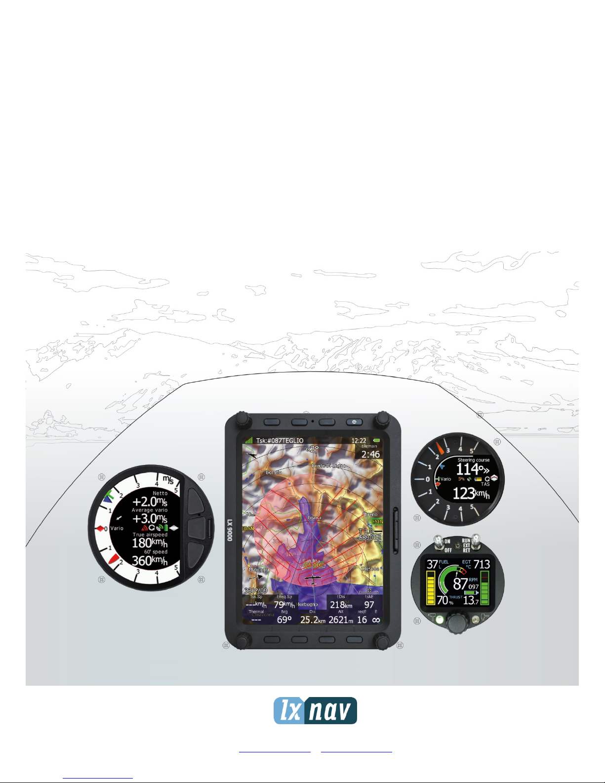
The system consists of two units; the main display unit and the vario unit. Within the main
display unit an integral 50-channel GPS receiver and a high brightness colour display are
fitted. An integrated SD card or USB interface is used for user friendly data exchange.
Some of the models are featuring also PDA port for easy connection on external PDA device.
The main display unit is equipped with a built-in flight recorder according to the most recent
IGC specification for all flights. Optionally the FLARM collision avoidance system can be
integrated into the main display unit.
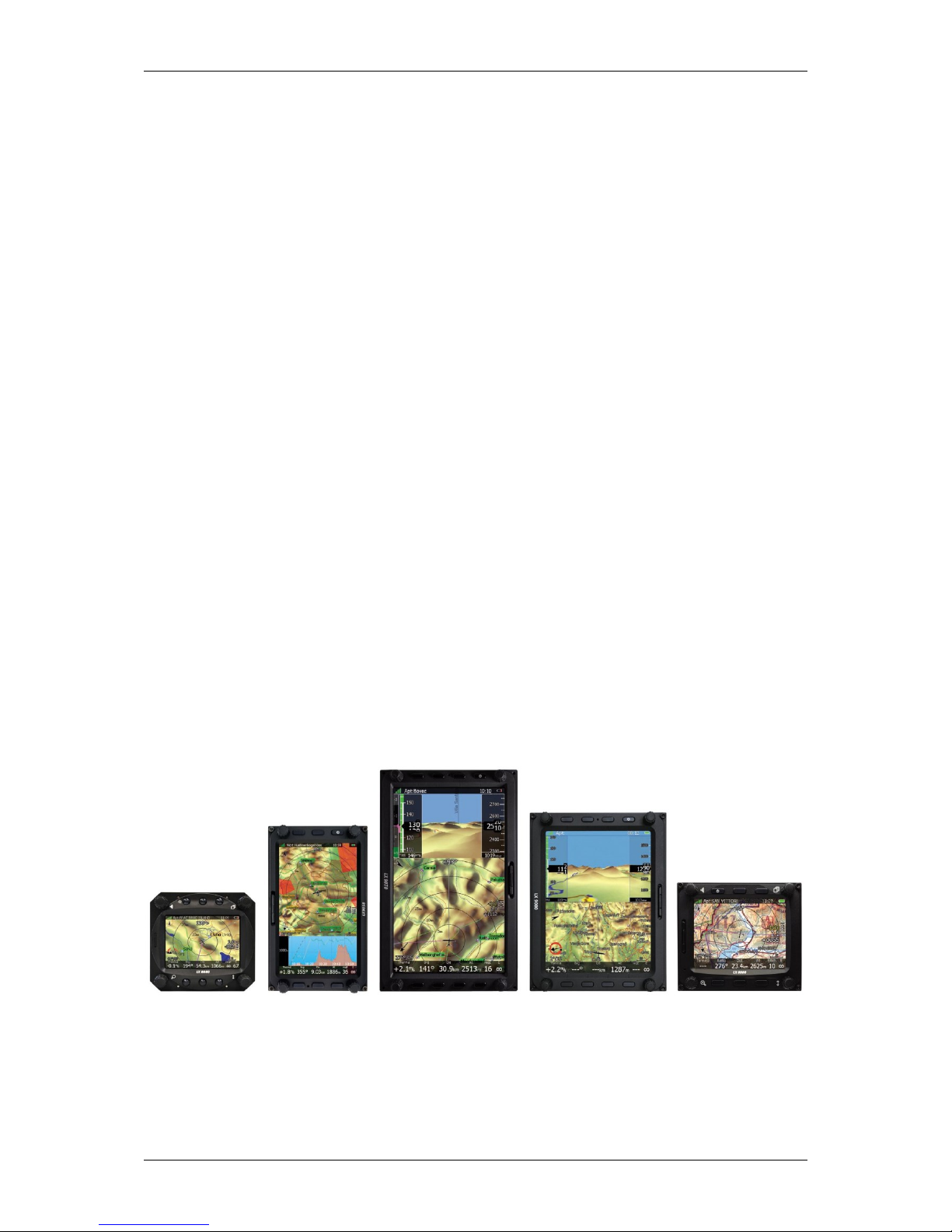
Main display unit came in different forms:
LX8080 model with 2.8” screen and 320x240 pixels resolution,
LX8000 model with 3.5” screen and 320x240 pixels resolution,
LX9050 model with 5.0” screen and 800x480 pixels resolution,
LX9000 model with 5.6” screen and 640x480 pixels resolution
and
LX9070 model with 7.0” screen and 800x480 pixels resolution.
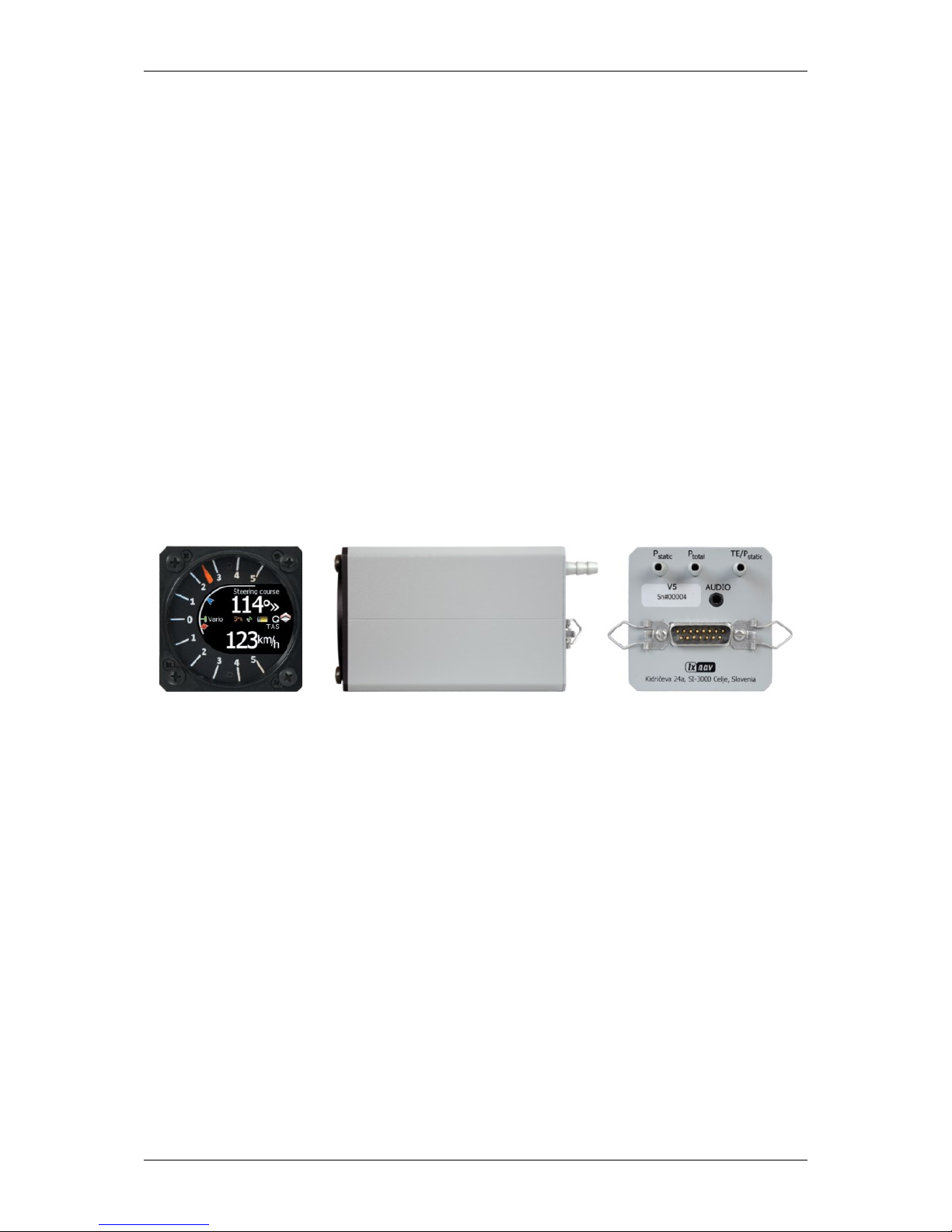
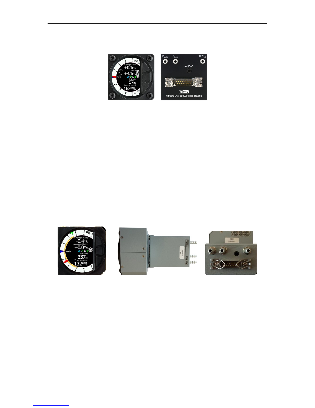
Standard part of system is also the V9 vario unit. It is a most modern variometer running
on very powerful processor with inertial platform using 3 axis accelerometer, 4 gyroscopes
(for inertial vario, AHRS and wind calculation), smooth audio output with audio equalizer and
integrated synthesized speech output. The unit communicates with the main display unit
over the RS485 system bus. V9 vario features 57 mm diameter (2¼") indicator with
mechanical needle and colour display for additional data.
Optional vario units are available:
V80 vario features 80 mm diameter (3”) colour screen and three additional buttons or V8
vario with 57 mm diameter (3”) colour screen and three additional buttons. Sensors in both
options are same as in V9 variometer.
Optionally additional vario indicators and a wide range of interface devices can be daisychained using the RS485 bus.
2.1.1 Display Unit Features
Extremely bright colour display readable in all sunlight conditions with backlight
automatically adapted using an ambient light sensor (ALS).
Using Linux operating system (not CE Windows) ensures fast and stable operation of the
firmware.
LX90xx/LX80xx Version 5.0 June 2015
Page 10 of 166
6 or 8 push buttons and 4 rotary switches (knobs) are used for input, which comprise
the well-known LX user interface. Optionally a remote stick is available for more
comfort.
Portrait or landscape orientation. (Portrait orientation is not available on LX80xx models)
Pre-loaded with worldwide terrain maps, airspace and airport databases.
Unlimited number of waypoints.
Unlimited number of tasks (with assigned area support).
Comprehensive flight and task statistics.
Display of nearest airports and out-landing fields.
Unlimited number of pilots/profiles.
Integrated flight recorder according to high-level IGC specification.
Real-time flight optimisation according to FAI and OLC rules.
Flights stored in IGC format are downloadable using the integrated SD Card.
Flight recorder functions include an integral pressure transducer based on 1013 mbar
level for altitude recording, engine noise level sensor, memory to store more than 1000
hours of flights and digital and mechanically security devices to ensure high level of
security.
Integrated FLARM collision avoidance system with graphic, sound and voice (optional)
presentation.
2.1.2 V9 Vario Unit Features
ARM Cortex-M4 processor running on 160MHz
Mechanical needle driven by stepper motor
QVGA (320*240pixels) sunlight readable display
Digital temperature compensated pressure sensors for altitude and airspeed
inertial platform 3 axis digital +-6g accelerometer, 3 axis gyroscopes (for inertial
vario, AHRS and wind calculation)
Smooth audio output
Audio equalizer
integrated synthesized speech output
audible thermal assistant
6 digital inputs - SC, VP + 4 custom defined
Multilanguage user interface
LX90xx/LX80xx Version 5.0 June 2015
Page 11 of 166
2.1.3 V8 Vario Unit Features
ARM Cortex-M4 processor running on 160MHz
2.5'' QVGA sunlight readable screen with 1200nits
QVGA (320*240pixels) sunlight readable display
Digital temperature compensated pressure sensors for altitude and airspeed
inertial platform 3 axis digital +-6g accelerometer, 4 gyroscopes (for inertial vario,
AHRS and wind calculation)
Smooth audio output
Audio equalizer
integrated synthesized speech output
audible thermal assistant
External SD card for configuration, FlarmNet and firmware update
push buttons for setting adjustments
ALS (ambient light sensor)
2.1.4 V80 Vario Unit Features
Dual ARM Cortex-M4 processor
Extremely bright 3.5" (8.8 cm) colour display with 320x240 pixels is used to display
vario needle and additional information such as average, thermal vario, time, speed
etc…
No mechanical parts and fast refresh rate allows extremely fast response time of needle.
Additional Flarm radar screen and artificial horizon.
Three buttons for toggling between screen and target selection
digital temperature compensated pressure sensors for altitude and airspeed
inertial platform 3 axis digital +-6g accelerometer, 4 gyroscopes
Smooth audio output with audio equalizer and many custom audio settings
Integrated voice module
100Hz sampling rate for very fast response.
Speed to fly indication.
LX90xx/LX80xx Version 5.0 June 2015
Page 12 of 166
TE compensation can be selected to be either pneumatic TE probe or digital
compensation.
2.1.5 Interfaces
The RS232 interface has NMEA output for external devices.
An SD Card interface.
A USB slot for data transfer using USB memory stick.
2.1.6 Internal Options
Flarm module can be built into the main display unit. All necessary connectors are
available on the rear side of the unit (Flarm external indicator, Flarm antenna), which
guaranties the same comfort as with the original Flarm devices. It is very important to point
out that the whole system uses only one GPS receiver and therefore offers a low power
solution.
Artificial horizon can be enabled on main display unit. Vario sensor box is constantly
using data from inertial platform in order to make vario signal smoother, however if pilot
would like to see artificial horizon and software option to do so must be purchased.
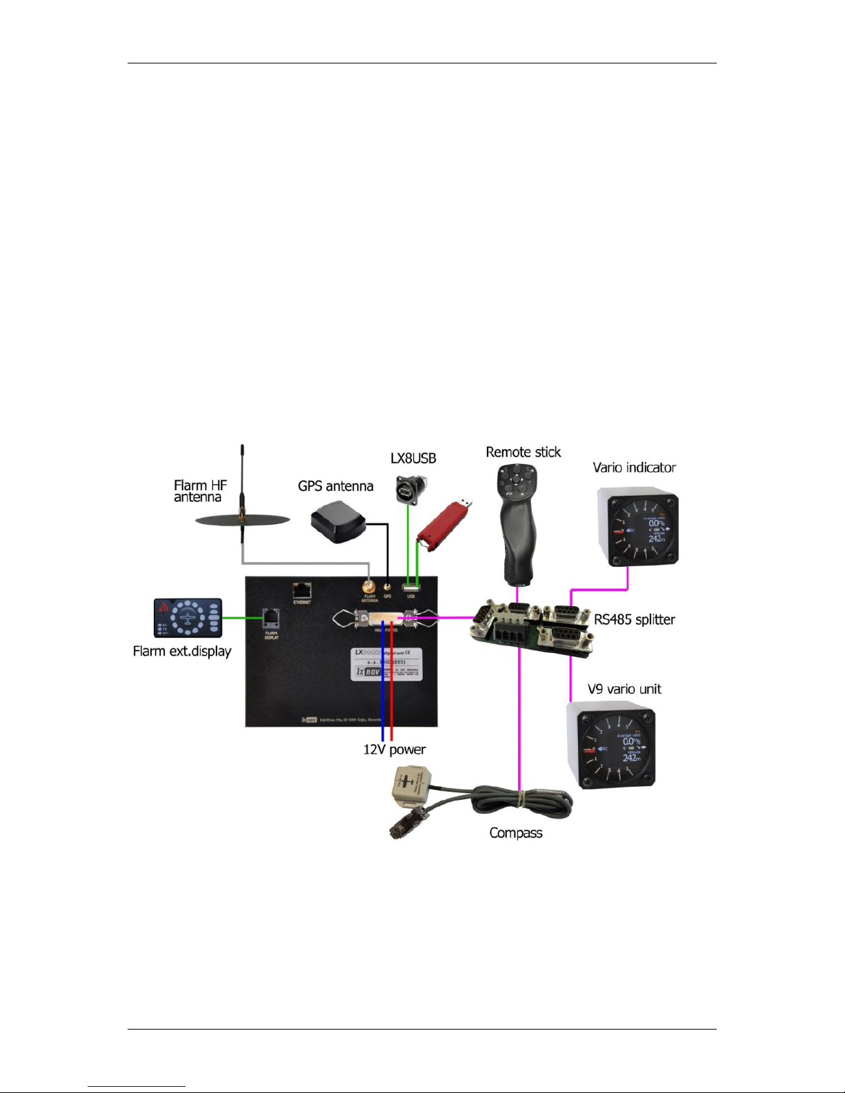
2.1.7 External Options
By using a RS485 bus system a wide range of optional interfaces can be easily connected to
the basic configuration with minimal installation work. The LXNAV bus system can be
extended easily by use of RS485 splitting units, which allow plug and play connection of
optional devices. The following units can be connected to the main system:
Second Seat Device (LX9000D, LX9050D LX9070D LX8000D or LX8080D):
The unit installed in the rear seat of the glider is powered and receives all necessary

LX90xx/LX80xx Version 5.0 June 2015
Page 13 of 166
data from the main unit. The communication between both units is exclusively via the
RS485 bus system.
Remote Control: An extremely ergonomic leather-coated handle which includes 8
push buttons to operate the main display unit and also two additional buttons with open
wires. These two buttons can be used for instance as PTT for radio and SC/Vario
changeover command. A second remote control can be installed to control second seat
device or for side by side operation.
Electrical Compass Device
Secondary Vario Indicators (I8,I9 or I80 indicator)
Flap sensor
MOP box for jet engines
2.1.8 Simulator
There are two options to stay in condition and familiar with your system. LXSim is free of
charge program, which you can download from www.lxnav.com or data from the Condor PC
flight simulator (www.condorsoaring.com) can be received via the RS232 port after entering
suitable passwords (see Chapter 5.1.15).
These features are extremely useful for pilots who want to learn about the system and also
wish to refresh their knowledge after a winter break. Please note that altitude data will be
sent from the simulator which means that real final glide training will be possible.

LX90xx/LX80xx Version 5.0 June 2015
Page 14 of 166
2.1.9 Technical Data
2.1.9.1 LX9000 System
Power input 10-16 V DC
Consumption at 12 V:
o 250 mA - minimum brightness without audio and options.
o 260 mA - minimum brightness without audio and with Flarm.
o 470 mA - maximum brightness without audio and options.
o 480 mA - maximum brightness without audio and with Flarm.
o 160 mA – additional for V9 vario unit
Cut-out dimensions of the LX9000 display unit are 109 x 143 mm; outline dimensions:
113 x 145 x 38 mm exclusive connector.
57 mm (2¼") standard aircraft cut-out for the V9 vario unit; length 92 mm (exclusive
connector).
80 mm (3") standard aircraft cut-out for the V80 vario unit; length 130 mm (exclusive
connector).
2.1.9.2 LX9050 System
Power input 10-16 V DC
Consumption at 12 V:
o 250 mA - minimum brightness without audio and options.
o 260 mA - minimum brightness without audio and with Flarm.
o 470 mA - maximum brightness without audio and options.
o 480 mA - maximum brightness without audio and with Flarm.
o 160 mA – additional for V9 vario unit
Cut-out dimensions of the LX9050 display unit are 134 x 79 mm; outline dimensions:
136 x 83 x 61 mm exclusive connector.
57 mm (2¼") standard aircraft cut-out for the V9 vario unit; length 92 mm (exclusive
connector).
80 mm (3") standard aircraft cut-out for the V80 vario unit; length 130 mm (exclusive
connector).
2.1.9.3 LX9070 System
Power input 10-16 V DC
Consumption at 12 V:
o 250 mA - minimum brightness without audio and options.
o 260 mA - minimum brightness without audio and with Flarm.
o 470 mA - maximum brightness without audio and options.
o 480 mA - maximum brightness without audio and with Flarm.
o 160 mA – additional for V9 vario unit
Cut-out dimensions of the LX9070 display unit are 109 x 179 mm; outline dimensions:
113 x 181 x 38 mm exclusive connector.
57 mm (2¼") standard aircraft cut-out for the V9 vario unit; length 92 mm (exclusive
connector).
80 mm (3") standard aircraft cut-out for the V80 vario unit; length 130 mm (exclusive
connector).
2.1.9.4 LX8000
Power input 10-16 V DC
Consumption at 12 V:

LX90xx/LX80xx Version 5.0 June 2015
Page 15 of 166
o 290 mA - minimum brightness without audio and options.
o 300 mA - minimum brightness without audio and with Flarm.
o 380 mA - maximum brightness without audio and options.
o 390 mA - maximum brightness without audio and with Flarm.
o 160 mA – additional for V9 vario unit
Cut-out dimensions of the LX8000 digital unit are 93.5 x 81.5 mm; outline dimensions:
98 x 88 x 115 mm exclusive connector.
57 mm (2¼") standard aircraft cut-out for the V9 vario unit; length 92 mm (exclusive
connector).
80 mm (3") standard aircraft cut-out for the V80 vario unit; length 130 mm (exclusive
connector).
2.1.9.5 LX8080
Power input 10-16 V DC
Consumption at 12 V:
o 160mA at 50% LCD brightness (600nits still readable under sunlight)
o 260mA with integrated Flarm at 100% LCD brightness (1200nits)
o 160 mA – additional for V9 vario unit
Cut-out dimension of the LX8080 digital unit is 80 mm (3") standard aircraft cut-out;
outline dimensions are 81mm x 81mm x 65mm exclusive connector.
57 mm (2¼") standard aircraft cut-out for the V9 vario unit; length 92 mm (exclusive
connector).
80 mm (3") standard aircraft cut-out for the V80 vario unit; length 130 mm (exclusive
connector).
2.1.10 Weight
LX9000 display unit: 650 g
LX9050 display unit: 515 g
LX9070 display unit: 650 g
LX8000 digital unit: 580 g
LX8080 digital unit: 400 g
V9 vario unit: 300 g

LX90xx/LX80xx Version 5.0 June 2015
Page 16 of 166
3 Packing Lists
3.1 LX90xx with Flarm Option
LX9000, LX9050 or LX9070 main display unit
V9 vario unit (optional V80 or V8)
Main power cable for main display unit
Cable for vario unit
SD card
Barogram calibration chart
GPS antenna
Flarm Antenna
Hex key “Inbus”
3.2 LX90xx
LX9000, LX9050 or LX9070 main display unit
V9 vario unit (optional V80 or V8)
Main power cable for main display unit
Cable for vario unit
SD card
Barograph calibration chart
GPS antenna
Hex key “Inbus”
3.3 LX90xxD
LX9000D or LX9050 or LX9070D
Main power cable
RS485 cable – 4 meter
RS485 splitting unit
Vario indicator I9 (Optional I80 or I8)
SD card
Hex key “Inbus”
3.4 LX80xx with Flarm Option
LX8000 or LX8080 main display unit
V9 vario unit (optional V80 or V8)
Main power cable for main display unit
Cable for vario unit
SD card
Barogram calibration chart
GPS antenna
Flarm Antenna
Hex key “Inbus”
3.5 LX80xx
LX8000 or LX9080 main display unit

LX90xx/LX80xx Version 5.0 June 2015
Page 17 of 166
V9 vario unit (optional V80 or V8)
Main power cable for main display unit
Cable for vario unit
SD card
Barograph calibration chart
GPS antenna
Hex key “Inbus”
3.6 LX80xxD
LX8000D or LX8080
Main power cable
RS485 cable – 4 meter
RS485 splitting unit
Vario indicator I9 (Optional I80 or I8)
SD card
Hex key “Inbus”
LX90xx/LX80xx Version 5.0 June 2015
Page 18 of 166
4 System Description
The main display unit of LX90xx series can be mounted at portrait or landscape orientation.
Only After installing the main display unit, the orientation must be defined via the Display
menu (see Chapter 5.1.4).
The main display unit of LX80xx series can be mounted only in landscape mode.
In this manual all screenshots are given for portrait orientation of the LX9000
system, which is most commonly used. However all functionality is the same in
any other configuration of system. Small differences are going to be marked
further in manual.
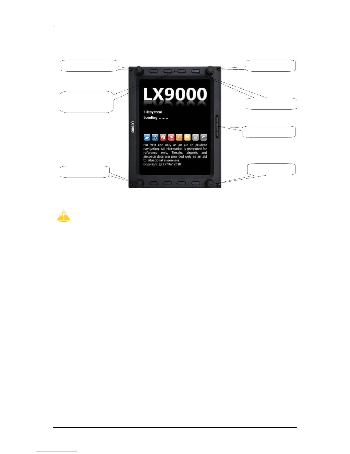
4.1 Rotary Switches and Buttons
The following controls are mounted on the front face of the main display unit:
Four rotary selector knobs
Eight (lx90xx) or six (lx80xx) push-buttons
SD card reader
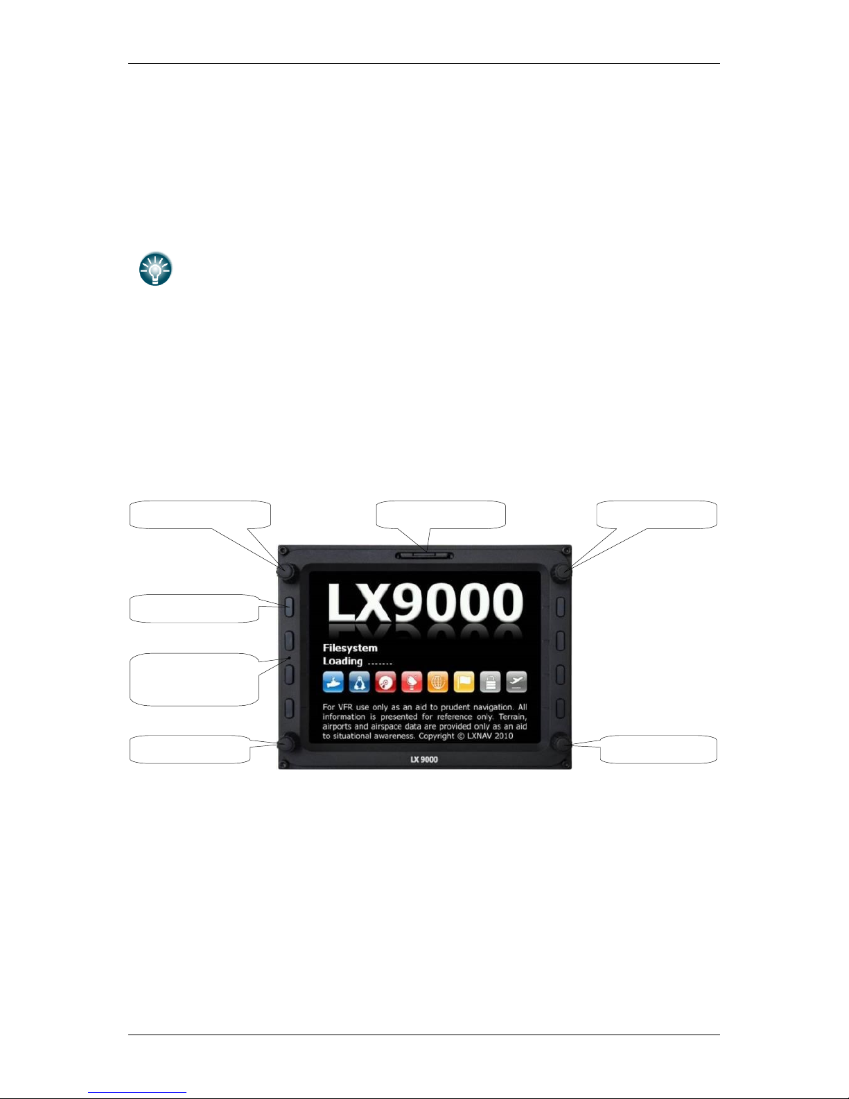
4.1.1 Landscape orientation
VOLUME selector
MODE selector
SD Card reader
ZOOM selector
PAGE selector
POWER button
Ambient light
sensor
LX90xx/LX80xx Version 5.0 June 2015
Page 19 of 166
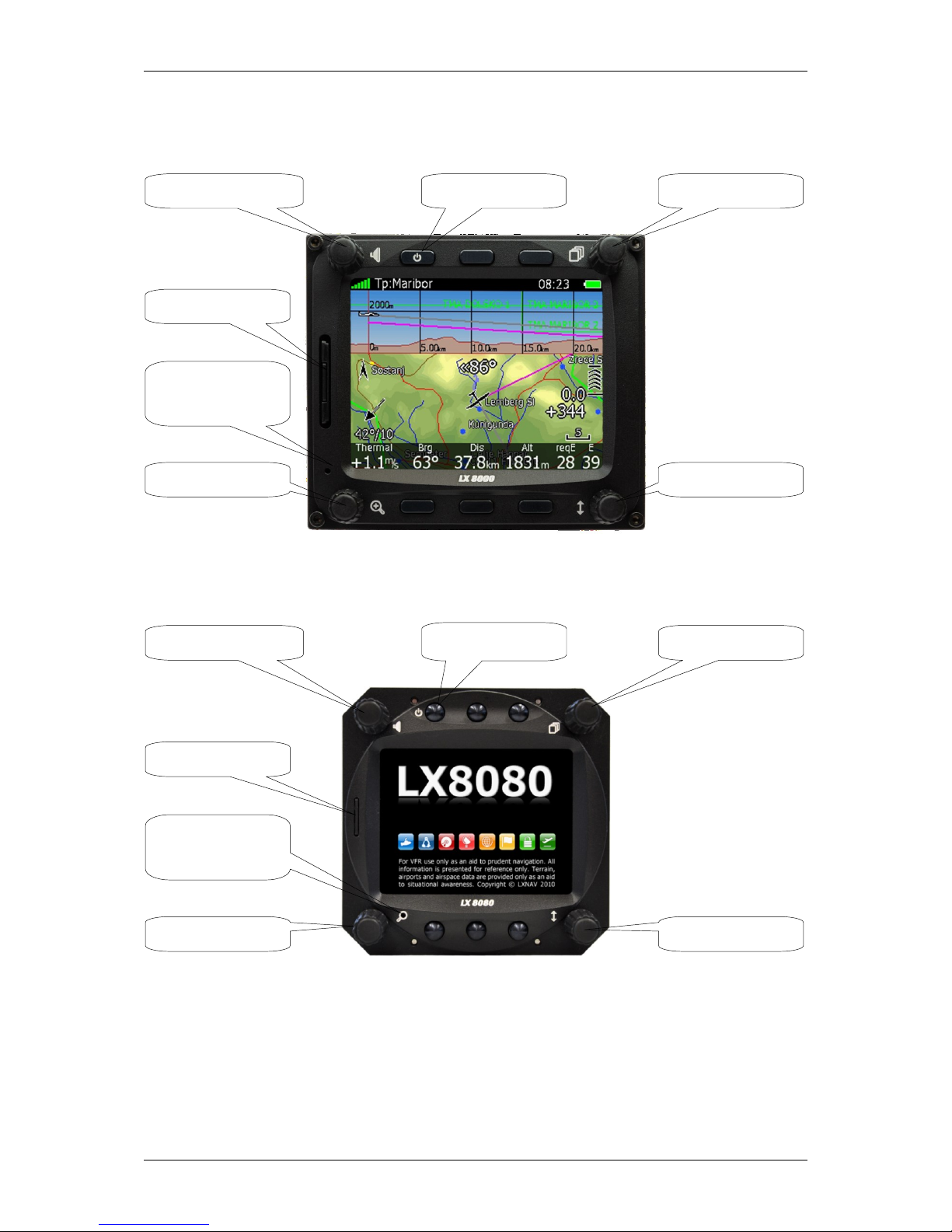
VOLUME selector
MODE selector
POWER button
ZOOM selector
PAGE selector
SD Card reader
Ambient light
sensor
VOLUME selector
MODE selector
POWER button
ZOOM selector
PAGE selector
SD Card reader
Ambient light
sensor
LX90xx/LX80xx Version 5.0 June 2015
Page 20 of 166
4.1.2 Portrait orientation
The V9 vario unit is an indicator only and has no controls. Information displayed
is controlled by the main display unit.
The V80 vario unit is having three buttons to toggle between screens. More
information is given in chapter 5.1.12.4.
4.1.3 Buttons
All buttons have a dynamic function; the first time one presses each button, it displays its
function without executing any action. Not all buttons have a function on every page. In
some cases buttons have a long press function.
4.1.3.1 Power Button
The power button is marked with the ON/OFF symbol. It has multiple functions. Primarily it
is used to switch the system on and off.
4.1.4 Rotary Switches (Knobs)
The main display unit has four rotary knobs. Each has a single function with the exception
of the zoom knob which has, in some cases, a function other than zoom. With the upperleft rotary knob the volume can be adjusted. The upper-right rotary switch is the mode
selector (it changes the mode of the operation). At the lower-right is the up/down knob
which is used for selecting sub-pages, sub-menus and editing menus. At the lower-left is
the zoom knob which is multifunctional. While its main function is to change the zoom level
within graphic mode, it can also be used if an error is made during editing; it is possible to
move the cursor back by rotating this knob. However this can only be done if 'editing' is
active which is shown by the cursor blinking.
VOLUME selector
MODE selector
SD Card reader
ZOOM selector
PAGE selector
POWER button
Ambient light
sensor
LX90xx/LX80xx Version 5.0 June 2015
Page 21 of 166
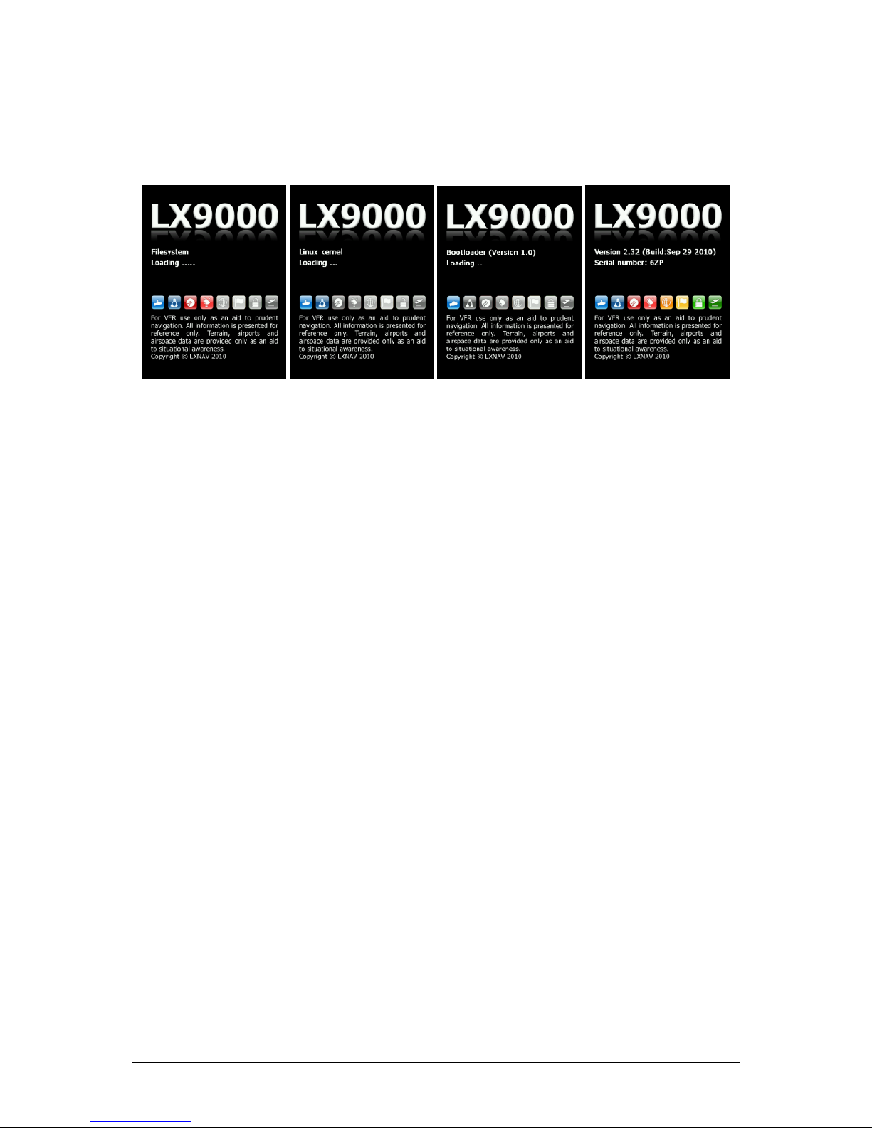
4.2 Switching on the Unit
After a short press of the power-on button the main display unit and vario unit will turn on
and a welcome screen will appear. The first screen shows the boot loader screen followed
by the Linux kernel screen and then the file system screen.
The boot procedure normally takes up to 20 seconds but in the case of a firmware update or
system check it can take more time. The final boot screen displays information about the
LX90xx system firmware and the IGC serial number. When the boot procedure is completed
the profile selection dialogue is shown. Please refer to Chapter 8.1 for more details about
starting up the system.
4.3 User Input
The main display unit user interface consists of many dialogues which have different input
controls. They are designed to make input of names, parameters, etc., as easy as possible.
Input controls can be summarised as:
Text editor
Masked text editor
Spin controls
Selection control
Checkboxes
Colour selector
Line width selector
To move the function from one control to another, rotate the PAGE selector knob (page
selector) as follows:
Clockwise rotation will select the next control.
Counter clockwise rotation will select the previous control. Press the SELECT button
(usually lower-right) to enter control input.
LX90xx/LX80xx Version 5.0 June 2015
Page 22 of 166
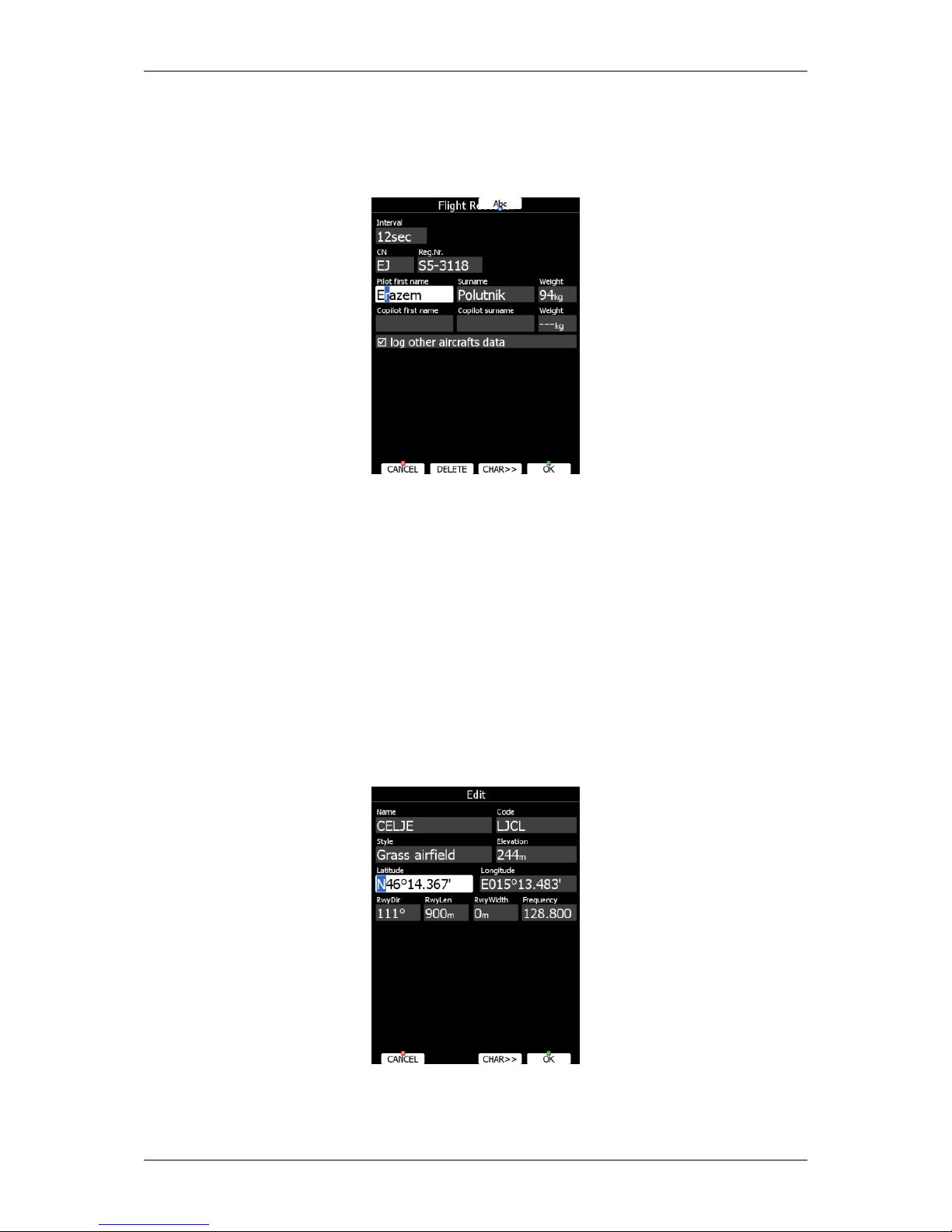
4.3.1 Text Edit Control
The Text Editor is used to input an alphanumeric string of arbitrary length; the picture below
shows typical options when editing text. Use the bottom-right knob to change the value at
the current cursor position.
Press the CHAR>> button to advance the cursor to the next position. The cursor can also
be moved to next position using the bottom-left knob. Rotate it clockwise to move forward.
The Abc button is a toggle button and will change the letter case. Press it to toggle modes.
Abc mode will start every new word with a capital letter; subsequent letters will be
lower case.
ABC mode will enter only upper case letters.
abc mode will enter only lower case letters.
Pressing the DELETE button will delete the character at current cursor position. Continually
press the DELETE button to delete all characters after the current cursor position.
Press OK to confirm changes and leave control. Press CANCEL to abandon changes and
revert back to the values before entering this screen.
4.3.2 Masked Text Edit Control
The masked editor is a similar control to the text editor but only limited characters can be
entered at any particular position. It is designed to enter latitude, longitude and passwords.
LX90xx/LX80xx Version 5.0 June 2015
Page 23 of 166
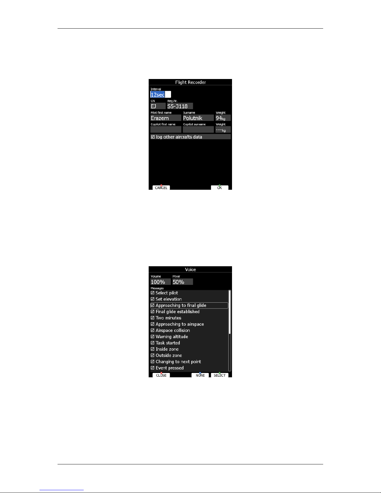
4.3.3 Spin Control
Spin controls are designed for numeric parameters. Rotate the bottom-right knob (page
selector) to increase/decrease the selected value. The bottom-left (zoom) knob will
increase/decrease the value with a different step compared to the page selector.
4.3.4 Selection Control
Selection boxes, also known as combo boxes on Windows operating system, are used to
select a value from list of predefined values. Use the page selector to scroll through the list.
4.3.5 Checkbox and Checkbox List
A checkbox enables or disables a particular parameter. Press SELECT to toggle the value.
If an option is enabled a check mark will be shown, otherwise an empty rectangle will be
displayed.
Use page selector to scroll through the checkbox list. Press the ALL to enable all options.
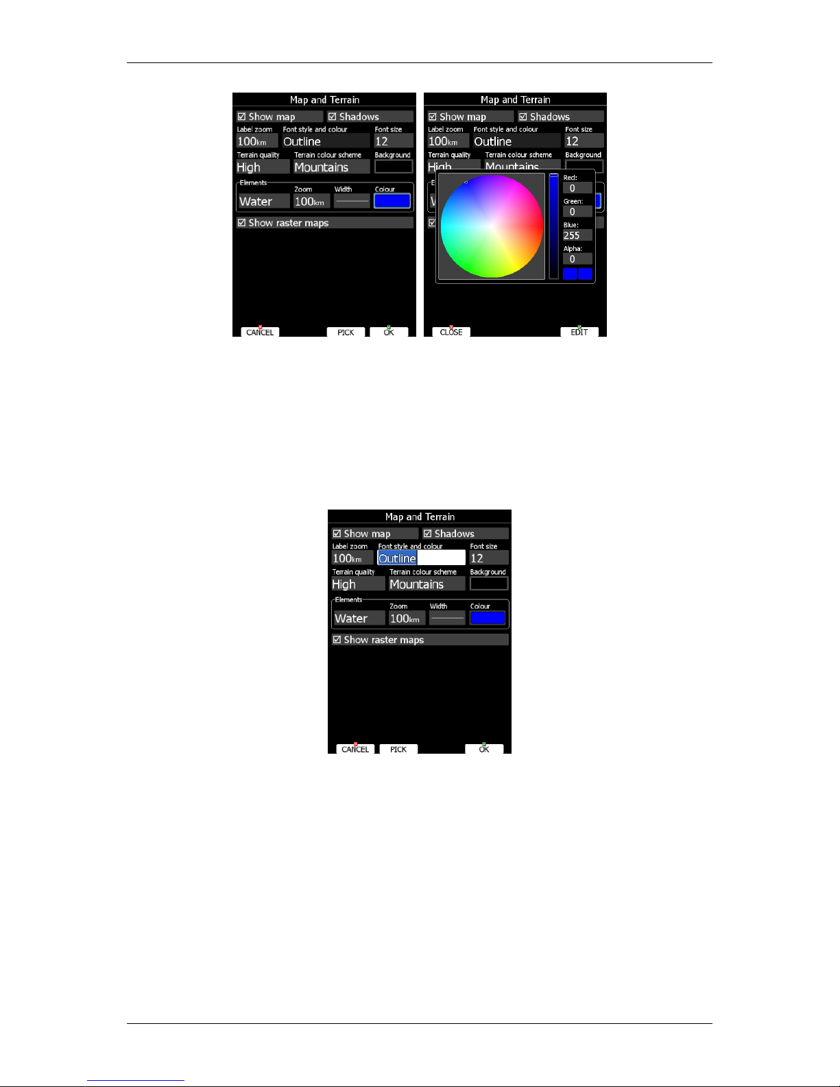
4.3.6 Colour Selector
Colours and fills are set via the colour selector control. Rotate the page selector to change a
colour.
LX90xx/LX80xx Version 5.0 June 2015
Page 24 of 166
Rotating the zoom selector changes colour transparency. Transparency is very important for
fill colours which are used for airspace zones, observation zones and FAI area. If a fill
colour is not transparent (0%), all other map items will not be seen through it. If a fill
colour is 100% only the solid border will be drawn.
Press PICK button to define colour more precisely. A colour dialog will open, where you can
select colour from HSV circle or enter values for red, green and blue colour.
4.3.7 Font Selector
Using the font selector it is possible to define a font colour and style for a selected item.
Turn the PAGE selector knob (page-selector) to change the font style. Text is also rendered
in the selected font style. Turn the ZOOM selector knob (zoom-selector) to change the font
colour.
Press PICK button to define colour more precisely. A colour dialog will open, where you can
select colour from HSV circle or enter values for red, green and blue colour.
4.3.8 Line pattern Selector
Using line pattern selector it is possible to define width and pattern of line. Turn the PAGE
selector knob (page-selector) to change the width of line. Turn the ZOOM selector knob
(zoom-selector) to change the line pattern. Results are immediately visible on selected
item.
LX90xx/LX80xx Version 5.0 June 2015
Page 25 of 166
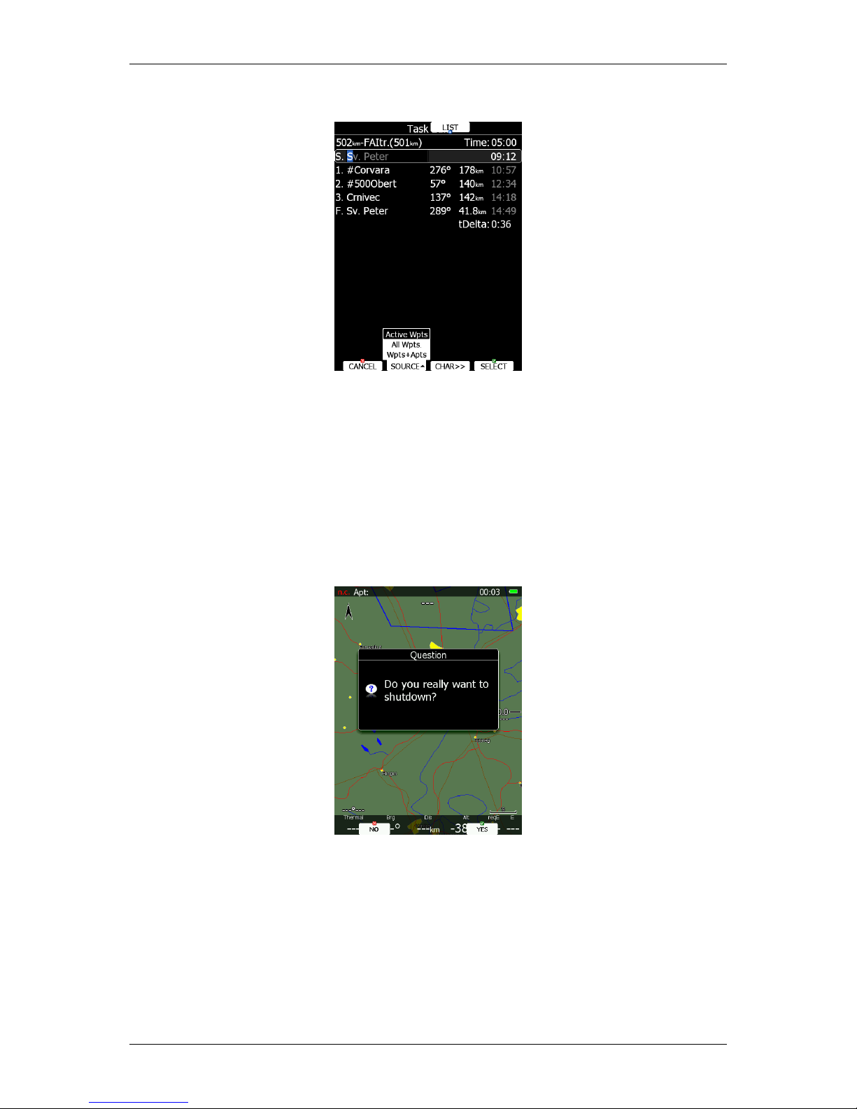
4.3.9 Pull down menu
Pull down menu is used to select one of the options. Press button several times to select
appropriate item of turn PAGE selector knob. Pull down menu will automatically close after
few seconds.
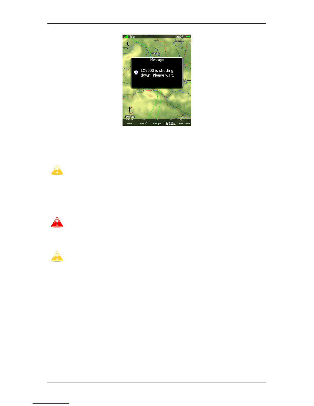
4.4 Switching off
Please use one of the following recommended methods for shutting down the LX90xx
system:
Method 1
Press the button with the OFF label which is displayed in navigational modes. See Chapter
5.5 for more details. A message to confirm shutdown will be shown.
Method 2
Press the button with the OFF symbol for approximately 4 seconds. The OFF message will
be displayed and the instrument will shut down. When the message appears you must
release the power button.
LX90xx/LX80xx Version 5.0 June 2015
Page 26 of 166
Method 3
When the button with the OFF symbol is pressed for more than 8 seconds the system will
perform an unconditional shutdown. This method is recommended only in case that the
program hangs and it is not possible to shutdown with methods 1 or 2.
If you are using method 2 to switch off the system it is necessary to release the
button when you see the shutting down message. If you continue to press the off
button the main display unit may shut down by method 3.
If the request for OFF is made during flight the instrument will ask for confirmation so that
the system cannot be switched off by mistake.
It is important that the main display unit is switched off via software. Never
power down the system using the main power switch. The main display unit is
running the Linux operating system and sudden power loss may corrupt the file
system.
If main power is lost for a few seconds during flight the flight recorder will not
produce two flights. The most important flight parameter (altitude) will remain
which means that the final glide calculations are not affected.
LX90xx/LX80xx Version 5.0 June 2015
Page 27 of 166
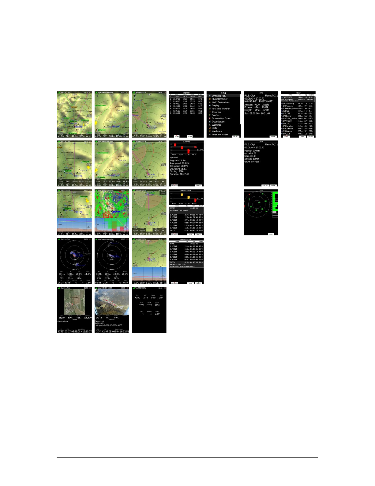
5 Operating Modes
The main display unit has seven modes or main menus. All of them are selectable by
rotating the upper-right knob which is also called MODE selector. The diagram below
shows the mode structure of the LX9000 running in portrait screen.
Airport Mode, navigation and selection airports.
Waypoint Mode, navigation, selection and editing waypoints.
Task Mode, Navigation, selection and editing task.
Statistics Mode shows statistical data for flight in progress or logbook.
Setup mode is used to configure the whole system.
Information Mode displays GPS status, altitude, flight level and height, sunrise and
sunset or position report to selectable point or satellite sky view.
Near Mode displays a list of all landable waypoints and airports.
The Navigation modes and statistics mode have additional pages which are accessible by
rotating the bottom-right knob also called the PAGE selector.

LX90xx/LX80xx Version 5.0 June 2015
Page 28 of 166
Three main navigational modes airport, waypoint and task mode are selected by
rotating the upper-right knob. All three options are similar and have similar basic navigation
data screens accessed by rotating the bottom-right knob.
It is possible to fully customise all three main navigational pages using the
program LXStyler. This program can be downloaded from our webpage
www.lxnav.com. Refer to Chapter 5.1.14 for more details.
It is also possible to customise selected navigational pages using STYLE menu
option. Refer to Chapter 6 for more details.
In airport navigation mode the user can navigate only to airports stored in LXNAV's Airports
database. This database cannot be edited on device itself and is available at no charge on
our web pages. See Chapter 5.1.5.2 for more details how to obtain the latest databases.
Database can be modified using program LXAsapt editor. This program can be
downloaded from our webpage www.lxnav.com
In waypoint navigation mode the user is navigating to waypoints that were previously
loaded and selected in the Files and Transfer menu (see Chapter 5.1.5.4).
Task navigation mode is used for task creation and manipulation. Navigation in this page is
exclusively to task points.
LX90xx/LX80xx Version 5.0 June 2015
Page 29 of 166
5.1 Setup Mode
In the setup menu users can configure the main display unit and connected devices. Turn
the bottom-right knob - PAGE selector - or press the UP/DOWN arrow on the remote stick to
select the appropriate setup item. Turn the bottom-left knob - ZOOM selector - or press the
LEFT/RIGHT arrow on the remote stick to move faster over menu. Press the SELECT
button or push middle multi-directional button on the remote stick to enter a menu. A
dialogue or sub-menu will open.
The setup menu is slightly different on the rear seat device as not all options are applicable.
Items which are marked with an asterisk (*) are available only in the front seat setup menu.
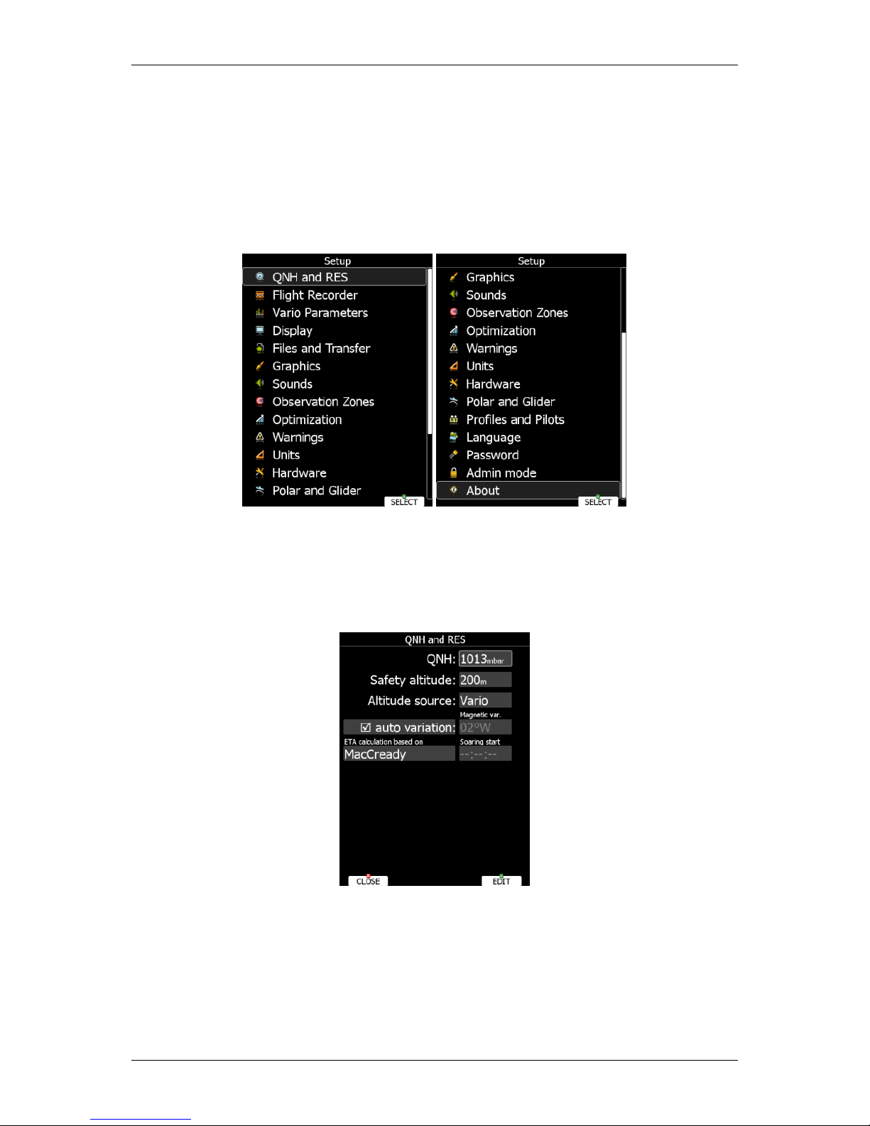
5.1.1 QNH and RES
Turn the bottom-right knob to select the required entry field. Press the EDIT button and
start editing the value.
5.1.1.1 QNH*
Using this feature it is possible to offset the altitude datum which could have changed due
to pressure changes during the flight. Since changing the QNH influences the indicated
altitude, care should be taken when changing the value as an incorrect setting can upset the
final glide calculation.

LX90xx/LX80xx Version 5.0 June 2015
Page 30 of 166
5.1.1.2 Safety Altitude
This setting is the altitude reserve or safety altitude and is the height that the instrument
adds to the final glide altitude required so that the glider arrives over the final glide
destination at the selected safety altitude. Once the safety altitude has been specified, the
pilot has to keep the final glide indicator on 0 to arrive at the safety altitude.
5.1.1.3 Altitude source
The system has two pressure altitude sensors. One is built into the main display unit and is
used for the IGC recorder and the second one is built into the vario unit and is connected to
the glider pitot-static system. Changing the altitude source defines which sensor is used for
pressure altitude used in program.
5.1.1.4 Magnetic Variation
The main display unit has a built-in Earth magnetic field model. If Auto variation is checked
the magnetic variation is derived from this model, otherwise the user can enter a custom
value.
5.1.1.5 ETA/ETE Calculation
In changing this value you may choose from four different methods to calculate the
estimated time of arrival to the navigational point. Calculation is always divided into straight
flight and climb time calculations.
MacCready uses the Polar data and MacCready setting to calculate speed to fly and
climb rate.
Vario uses the last four thermals average to compute climb rate and uses this value to
calculate speed to fly.
Avg.Speed & Vario uses the average ground speed over the last 5 minutes for
distance and Vario statistics for climb rate.
Avg.Speed & MC uses the average ground speed over the last 5 minutes for distance
and MacCready.
All four methods of calculating ETA and ETE (Estimate Time of Arrival & Estimate Time
Elapsed) take into account glider altitude, wind and safety (arrival) altitude thus ensuring
that the calculation made is the best possible.
Suggested methods for competition pilots are Avg.Speed & Vario or
Avg.Speed & Mc.
5.1.1.6 Soaring Start*
Soaring start is the time when the glider starts soaring (released from tow, engine switched
off). A soaring start time is needed to start the flight optimization.
 Loading...