

Page 1
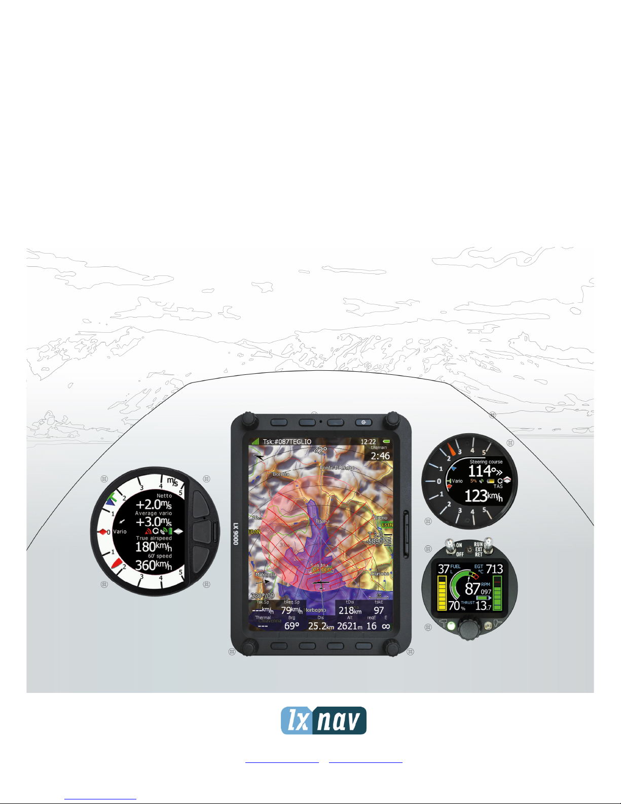
LX90xx and
LX80xx
System installation manual
LXNAV d.o.o. • Kidričeva 24a, 3000 Celje, Slovenia • tel +386 592 33 400 fax +386 599 33 522
info@lxnav.com
•
www.lxnav.com
Page 2

Page 3

1 Important Notices 5
1.1 Limited Warranty 5
2 Introduction 6
3 System planning 7
3.1 Power consumption 7
3.2 Power supply 9
3.3 Sizes and weights 10
3.4 Temperature specifications 11
3.5 Location requirements 11
3.5.1 LX9000 and Lx9070 11
3.5.2 Lx9050 12
3.5.3 LX8080 12
3.5.4 LX8000 12
3.5.5 V5, V9 vario 12
3.5.6 V8 vario 12
3.5.7 V80 vario 12
3.5.8 I9 and I8 vario indicators 12
3.5.9 I80 vario indicator 12
3.5.10 Flap sensor 13
3.5.11 Magnetic compass 13
3.5.12 FlarmLED and FlarmView 13
3.5.13 FlarmView57 13
3.5.14 Wi-Fi module 13
3.5.15 Bluetooth module 13
3.5.16 MOP sensor (for jet engine) 13
3.5.17 MOP sensor (for electric propulsion gliders) 13
3.5.18 Bridges 13
3.6 Cooling requirements 13
3.7 Mounting requirements 13
4 Overview of the system 14
4.1 Overview 14
4.2 Communication BUS 14
4.3 Harness and Cables 14
4.4 Splitters 15
4.5 Ethernet port 15
4.6 Available Cables and Harnesses 15
4.7 Examples of systems 17
5 Installation and Configuration 20
5.1 Main unit and repeater unit 20
5.1.1 Installation of Options 20
5.1.2 Cut-outs 21
5.1.2.1 Lx9000 cut-out 21
5.1.2.2 Lx9070 cut-out 22
5.1.2.3 Lx9050 cut-out 23
5.1.2.4 Lx8080 cut-out 23
5.1.2.5 Lx8000 cut-out 24
5.1.3 Dimensions 25
5.1.3.1 LX9000 dimensions 25
5.1.3.2 LX9070 dimensions 26
5.1.3.3 LX9050 dimensions 27
5.1.3.4 LX8080 dimensions 28
5.1.3.5 LX8000 dimensions 29
Page 4

5.1.3.6 V5, V9 dimensions 30
5.1.3.7 V8 dimensions 31
5.1.3.8 V80 dimensions 32
5.1.3.9 I5, I8 dimensions 32
5.1.3.10 I80 dimensions 32
5.1.1 Ports 33
5.1.1.1 LX9000 33
5.1.1.2 LX9050 33
5.1.1.3 LX9050 simple 34
5.1.2 LX8000 Digital unit 34
5.1.3 LX8000 Digital unit Version 2 35
5.1.4 LX8080 Digital unit 35
5.1.5 LX8080 Digital unit Version 2 36
5.1.6 LX8080 Digital unit Simple Version 36
5.1.7 Flarm Port (for LX8000 Versions 1 – no 12V output) 37
5.1.7.1 Flarm port on LX9xxx 37
5.1.7.2 PDA port (RJ45 38
5.1.7.3 GPS ports (RJ11) only on Simple version 39
5.1.1 Wirings 39
5.2 Connection and Functionality Check of All Peripheral Units 39
5.2.1 Vario Unit 40
5.2.1.1 Connecting vario unit 40
5.2.1.2 Cut-outs 40
5.2.1.1 Wirings 41
5.2.1.2 Connection to the bus 42
5.2.1.3 Pneumatics 42
5.2.1.4 Audio 44
5.2.1.5 Inputs 44
5.2.2 Installation of Options 45
5.2.2.1 Remote Sticks 45
5.2.2.2 Flarm 46
5.2.2.3 External Flarm or Power Flarm 46
5.2.2.4 ADSB receiver 47
5.2.2.5 Additional indicators 50
5.2.2.6 Flap Sensor 50
5.2.2.7 485 to 232 bridge 50
5.2.2.8 Wi-Fi___33 53
5.2.2.9 Compass 53
5.2.2.10 AHRS 54
5.2.2.11 FES Bridge 54
5.2.2.12 JDU Bridge 54
5.2.2.13 FlarmLED display 55
5.2.2.14 FlarmView display 56
5.2.2.15 FlarmView57 display 57
5.2.2.16 Flarm ACL 59
5.2.2.17 Bluetooth module 60
6 Firmware updates 61
7 Troubleshooting 62
7.1 Export Diagnostic Files 62
8 Revision History 63
Page 5

Important Notices Version 1.0, June 2015
Page 5 of 65
1 Important Notices
The LXNAV system is designed for VFR use only as an aid to prudent navigation. All
information is presented for reference only. Terrain, airports and airspace data are provided
only as an aid to situation awareness.
Information in this document is subject to change without notice. LXNAV reserves the right
to change or improve their products and to make changes in the content of this material
without obligation to notify any person or organisation of such changes or improvements.
A Yellow triangle is shown for parts of the manual which should be read very
carefully and are important for operating the system.
Notes with a red triangle describe procedures which are critical and may result in
loss of data or any other critical situation.
A bulb icon is shown when a useful hint is provided to the reader.
1.1 Limited Warranty
This LXNAV product is warranted to be free from defects in materials or workmanship for
two years from the date of purchase. Within this period, LXNAV will, at its sole option,
repair or replace any components that fail in normal use. Such repairs or replacement will
be made at no charge to the customer for parts and labour, provided that the customer shall
be responsible for any transportation cost. This warranty does not cover failures due to
abuse, misuse, accident, or unauthorised alterations or repairs.
THE WARRANTIES AND REMEDIES CONTAINED HEREIN ARE EXCLUSIVE AND IN LIEU OF
ALL OTHER WARRANTIES EXPRESSED OR IMPLIED OR STATUTORY, INCLUDING ANY
LIABILITY ARISING UNDER ANY WARRANTY OF MERCHANTABILITY OR FITNESS FOR A
PARTICULAR PURPOSE, STATUTORY OR OTHERWISE. THIS WARRANTY GIVES YOU
SPECIFIC LEGAL RIGHTS, WHICH MAY VARY FROM STATE TO STATE.
IN NO EVENT SHALL LXNAV BE LIABLE FOR ANY INCIDENTAL, SPECIAL, INDIRECT OR
CONSEQUENTIAL DAMAGES, WHETHER RESULTING FROM THE USE, MISUSE, OR
INABILITY TO USE THIS PRODUCT OR FROM DEFECTS IN THE PRODUCT. Some states do
not allow the exclusion of incidental or consequential damages, so the above limitations may
not apply to you. LXNAV retains the exclusive right to repair or replace the unit or software,
or to offer a full refund of the purchase price, at its sole discretion. SUCH REMEDY SHALL
BE YOUR SOLE AND EXCLUSIVE REMEDY FOR ANY BREACH OF WARRANTY.
To obtain warranty service, contact your local LXNAV dealer or contact LXNAV directly.
June 2015 © 2015 LXNAV. All rights reserved.
Page 6

Introduction Version 1.0, June 2015
Page 6 of 65
2 Introduction
The printed version of this installation manual is in grayscale. Some figures and diagrams
are in colour information. Please refer to electronic version to see colours. The latest
electronic version of this manual can be downloaded on http://www.lxnav.com section
downloads-manuals.
This manual will guide you through installation process of all systems, components, basic
setup and check of the system.
Before use of any part of the system, please read and understand installation and
user manual!
Inside unit is not any serviceable part, so the unit must be taken to service at the
factory.
Opening unit by user will void warranty and airworthy
Page 7

System planning Version 1.0, June 2015
Page 7 of 65
3 System planning
In this chapter, installer will be informed, how and where can be installed particular parts of
equipment. Some parts have environmental and location requirements, some not.
3.1 Power consumption
Some modules get power supply from the main unit. These modules do not need a circuit
breaker. It is calculated for main unit. Other parts of equipment that are having its own
power supply, should have installed specified circuit breakers.
Page 8

System planning Version 1.0, June 2015
Page 8 of 65
Appro
ximate Current
consumption at 12V DC
Recommended circuit
breaker
LX9000 main unit
500mA (at max. brightness)
3A
LX9000F main unit
520mA (at max. brightness)
3A
LX9000D repeater unit
480mA (at max. brightness)
3A
LX9070 main unit
660mA (at max. brightne
ss) 3A LX9070F main unit
680mA (at max. brightness)
3A
LX9070D repeater unit
640mA (at max. brightness)
3A
LX9050 main unit
590mA (at max. brightness)
3A
LX9050F main unit
610mA (at max. brightness)
3A
LX9050D repeater unit
570mA (at max. brightness)
3A
LX8080 main unit
250mA (at max. brightness)
3A
LX8080F main unit
270mA (at max. brightness)
3A
LX8080D repeater unit
230mA (at max. brightness)
3A
LX8000 main unit
300mA (at max. brightness)
3A
LX8000F main unit
350mA (at max. brightness)
3A
LX800
0D repeater unit
250mA (at max. brightness)
3A
V5 Vario
150mA (no audio)
-
V9 Vario
130mA (no audio)
-
V80 Vario
180mA (no audio)
-
V8 Vario
150mA (no audio)
-
Vario indicator (57mm I5)
80mA
-
Vario indicator (57mm I8)
110mA
-
Vario indicator (80mm
I80) 100mA
-
Remote stick
20mA
-
Flap sensor
30mA
-
Magnetic compass
70mA
-
Radio bridge
20mA
-
Transponder bridge
20mA
-
NMEA bridge
20mA
-
PDA port *
800mA
- Wi-Fi
module
20mA
-
FES bridge
40mA
-
JDU bridge
40mA
-
Flarm LED display
30mA (with
out beeper)
-
FlarmView display
70mA
-
FlarmView
57 display
70mA
-
Flarm ACL
30mA (without current for
driving LEDs)
3A Bluetooth
module
10mA
-
MOP sensor
100mA
-
* Not on all types of devices
Page 9

System planning Version 1.0, June 2015
Page 9 of 65
3.2 Power supply
Min.
voltage
Nominal
voltage
Max
. Voltag
e LX9000 main unit
10V 12V 16V LX9000F main unit
10V 12V 16V LX9000D repeater unit
10V 12V 16V LX9070 main unit
10V 12V 16V LX9070F main unit
10V 12V 16V LX9070D repeater unit
10V 12V 16V LX9050 main unit
10V 12V 16V LX9050F main unit
10V 12V 16V LX9050D repeater unit
10V 12V 16V LX8080 main unit
10V 12V 16V LX8080F main unit
10V 12V 16V LX8080D repeater unit
10V 12V 16V LX8000 main unit
10V 12V 16V LX8000F main unit
10V 12V 16V LX8000D repeater unit
10V 12V 16V V5 Vario
12V (from RS485)
V9 Vario
12V (from RS485)
V80 Vario
12V (from RS485)
V8 Vario
12V (from RS485)
Vario indicator (57mm
I5) 12V (from RS485)
Vario indicator (57mm
I8) 12V (from RS485)
Vario indicator (80mm
I
80)
12V (from RS485)
Remote stick
12V (from RS485
)
Flap sensor
12V (from RS485)
Magnetic compass
12V (from RS485)
Radio bridge
12V (from RS485)
Transponder bridge
12V (from RS485)
NMEA bridge
12V (from RS485)
Wi-Fi___33
module
5V (from USB)
FES bridge
12V (from RS485)
JDU bridge
12V
(from RS485)
Flarm LED display
3.2V
3.3V (from Flarm port)
3.4V
FlarmView display
9V
12V (from Flarm port)
16V FlarmView
2 display
9V
12V (from Flarm port)
16V FlarmView
57 display
9V
12V (from Flarm port)
16V Flarm ACL
9V
12V 18V Bluetooth
module
5V (from PDA)
MOP sensor
12V
Page 10

System planning Version 1.0, June 2015
Page 10 of 65
3.3 Sizes and weights
Dimensions
Weight
LX9000 main unit
113 x 145 x 38 mm 615 g
LX9000F main unit
113 x 145 x 38 mm 635 g
LX9000D repeater unit
113 x 145 x 38 mm 615 g
LX9070 main unit
113 x 181 x 38 mm 630 g
LX9070F main unit
113 x 181 x 38 mm 650 g
LX9070D repeater unit
113 x 181 x 38 mm 630 g
LX9050 main unit
136 x 83 x 61 mm
515 g
LX9050F main unit
136 x 83 x 61 mm
535 g
LX9050D repeater unit
136 x 83 x 61 mm
515 g
LX8080 main unit
82 x 82 x
60 mm
435 g
LX8080F main unit
82 x 82 x
60 mm
454 g
LX8080D repeater unit
82 x 82 x
60 mm
435 g
LX8000 main unit
98 x 88 x
65 mm
500 g
LX8000F main unit
98 x 88 x
65 mm
520 g
LX8000D repeater unit
98 x 88 x
65 mm
500 g
V5 Va
rio 61 x 61 x 92 mm
300 g
V9 Vario
61 x 61 x 92 mm
310 g
V80 Vario
81 x 81 x 130 mm
400 g
V8 Vario
61 x 61 x 92 mm
305 g
Vario indicator (57mm V5)
61 x 61 x
42 mm 200 g
Vario indicator (57mm V8)
61 x 61 x
48 mm 200 g
Vario indicator (80mm V80)
81 x 81 x 44 mm
270 g
Remote stick
Approx. 150
mm App
rox. 290 g
Flap sensor
52 x 23 x 16 mm
Approx. 190 g
Magnetic compass
56 x 40 x 15 mm
Approx. 100 g
Radio bridge
52 x 32 x 16 mm
45 g
Transponder bridge
52 x 32 x 16 mm
45 g
NMEA bridge
52 x 32 x 16 mm 45 g Wi-Fi module
40 x 20 x 9 mm
16 g
FES bridge
61 x
32 x 16 mm
20 g
JDU bridge
61 x
32 x 16 mm
20 g
Flarm LED display
42mm x 25mm x 5mm
10 g
FlarmView display
65 x 42 x 11 mm 27 g FlarmView
57 display
60 x 60 x 26 mm 98 g FlarmView
2 display
65 x 42 x 18 mm 36 g
Flarm ACL
76
x 63 x 26 mm 75 g
Bluetooth
module
64 x 18 x 10 mm 8 g MOP sensor
66 x 50 x 25 mm 71 g
Page 11

System planning Version 1.0, June 2015
Page 11 of 65
3.4 Temperature specifications
Storage temperature
Operating temperature
LX9000 main unit
-40°C to +80°C
-30°C to +
60°C
LX9000F main unit
-40°C to +80°C
-30°C to +60°C
LX9000D repeater unit
-40°C to +80°C
-30°C to +60°C
LX9070 main unit
-40°C to +80°C
-30°C to +60°C
LX9070F main unit
-40°C to +80°C
-30°C to +60°C
LX9070D repeater unit
-40°C to +80°C
-30°C to +60°C
LX9050 main unit
-40°C
to +80°C
-30°C to +60°C
LX9050F main unit
-40°C to +80°C
-30°C to +60°C
LX9050D repeater unit
-40°C to +80°C
-30°C to +60°C
LX8080 main unit
-40°C to +80°C
-30°C to +60°C
LX8080F main unit
-40°C to +80°C
-30°C to +60°C
LX8080D repeater unit
-40°C to
+80°C
-30°C to +60°C
LX8000 main unit
-40°C to +80°C
-30°C to +60°C
LX8000F main unit
-40°C to +80°C
-30°C to +60°C
LX8000D repeater unit
-40°C to +80°C
-30°C to +60°C
V5 Vario
-40°C to +80°C
-2
0°C to +60°C
V9 Vario
-40°C to +80°C
-2
0°C to +60°C
V80
Vario
-40°C to +80°C
-2
0°C to +60°C
V8 Vario
-40°C to +80°C
-2
0°C to +60°C
Vario indicator (57mm I5)
-40°C to +80°C
-30°C to +60°C
Vario indicator (57mm I8)
-40°C to +80°C
-30°C to +60°C
Vario indicator (80mm I80)
-40°C to +80°C
-30°C to +60°C
Remote
stick
-40°C to +80°C
-30°C to +60°C
Flap sensor
-40°C to +80°C
-30°C to +60°C
Magnetic compass
-40°C to +80°C
-2
0°C to +60°C
Radio bridge
-40°C to +80°C
-30°C to +60°C
Transponder bridge
-40°C to +80°C
-30°C to +60°C
NMEA bridge
-40°C to +80°C
-30°C t
o +60°C
PDA port *
-40°C to +80°C
-30°C to +60°C
Wi-
Fi___33
module
-40°C to +80°C
-30°C to +60°C
FES bridge
-40°C to +80°C
-30°C to +60°C
JDU bridge
-40°C to +80°C
-30°C to +60°C
Flarm LED display
-40°C to +80°C
-2
0°C to +60°C
FlarmView display
-40°C
to +80°C
-30°C to +60°C
Flarm ACL
-40°C to +80°C
-30°C to +60°C
Bluetooth
module
-40°C to +80°C
-30°C to +60°C
3.5 Location requirements
3.5.1 LX9000 and Lx9070
- Requires 35 mm of space behind the panel
- main unit harness needs additionally 45 mm of the space
- Choose position, that display will be viewable
Page 12

System planning Version 1.0, June 2015
Page 12 of 65
3.5.2 Lx9050
- Requires 65 mm of space behind the panel
- main unit harness needs additionally 45 mm of the space
- Choose position, that display will be viewable
3.5.3 LX8080
- Requires 60 mm of space behind the panel
- main unit harness needs additionally 45 mm of the space
- Choose position, that display will be viewable
3.5.4 LX8000
- Requires 65 mm of space behind the panel
- main unit harness needs additionally 45 mm of the space
- Choose position, that display will be viewable
3.5.5 V5, V9 vario
- Requires 92 mm of space behind the panel
- V5 and V9 vario unit harness needs additionally 45 mm of the space
- Some space should be taken in account also for pitostatic tubes connection
- Choose position, that display will be viewable
- If the instrument panel is not at right angle, additional AHRS alignment is required
(V9)
3.5.6 V8 vario
- Requires 94 mm of space behind the panel
- V8 vario unit harness needs additionally 45 mm of the space
- Some space should be taken in account also for pitostatic tubes connection
- Choose position, that display will be viewable
- If the instrument panel is not at right angle, additional AHRS alignment is required
3.5.7 V80 vario
- Requires 130 mm of space behind the panel
- V80 vario unit harness needs additionally 45 mm of the space
- Some space should be taken in account also for pitostatic tubes connection
- Choose position, that display will be viewable
- If the instrument panel is not at right angle, additional AHRS alignment is required
3.5.8 I9 and I8 vario indicators
- Requires 43 mm of space behind the panel
- Cable connection needs additionally 45 mm of the space
- Some space should be taken in account also for pitostatic tubes connection
- Choose position, that display will be viewable
3.5.9 I80 vario indicator
- Requires 45 mm of space behind the panel
- Cable connection needs additionally 45 mm of the space
- Some space should be taken in account also for pitostatic tubes connection
- Choose position, that display will be viewable
Page 13

Version 1.0, June 2015
Page 13 of 65
3.5.10 Flap sensor
- Is connected to flap rod – please consult with glider manufacturer about installation
3.5.11 Magnetic compass
- The location should be magnetically benign.
- As far as possible of metal parts, power cables
- In case of small magnetic interferences is available user calibration
- Very important is orientation of the magnetic compass (compass has marked TOP
position and flight direction position)
3.5.12 FlarmLED and FlarmView
- Flarm display should be placed on visible place on panel
- They requires 15 mm of space behind the panel
- Cable will take additional 10 mm of space
3.5.13 FlarmView57
- FlarmView57 should be placed on visible place on panel
- It requires 28 mm of space behind the panel
- Cable will take additional 10 mm of space
3.5.14 Wi-Fi module
- It is plugged in USB port of main unit
- It will take additional 62 mm of space behind the panel
3.5.15 Bluetooth module
- It is plugged in PDA port of main unit (not available at all types)
- It will take additional 55 mm of space behind the panel
3.5.16 MOP sensor (for jet engine)
- It is installed in the engine compartment, so it can easily detect engine noise
3.5.17 MOP sensor (for electric propulsion gliders)
- It is installed near main power lines that are coming out of the battery and measures
the current from batteries.
3.5.18 Bridges
Bridges are designed to be installed into any convenient place of the glider.
3.6 Cooling requirements
In the moment there is no cooling requirements, if possible ventilation should pass through
instrument panel to exchange some warm air. That will drop the temperature behind the
panel for few degrees.
3.7 Mounting requirements
Most of LXNAV units are fastened with screws.
Page 14

Overview of the system Version 1.0, June 2015
Page 14 of 65
4 Overview of the system
4.1 Overview
LXNAV system consists of many different displays, units and sensors, which talk to each
other via LXNAV RS485 bus.
4.2 Communication BUS
Most devices in LXNAV system talk to each other via RS485 bus. We are using standard
SUBD-9 pin connectors. Bus signals can be split via RS485 splitters. More splitters can be
bridged together with RS485 bridge cables.
Another way of communication with peripheral devices is RS232 serial interface. This
interface is mostly used to connect 3rd party devices into LXNAV system (external Flarm,
ADSB, radio, transponder, PDA). For each device we have specially designed cable.
4.3 Harness and Cables
Main unit cable has two power supply wires (red for positive +12V DC and blue for ground
potential), RS485 bus cable with DB9 connector and serial RS232 cable with rounded 5 pin
connector. This rounded 5 pin connector is designed to be mounted in to the panel. It can
be used for connection with PDA device.
Vario harness has also one DB9 RS485 connector, which can be directly plugged in RS485
connector from main unit. In case, we need to connect additional RS485 device (Remote
stick, flap sensor, Magnetic compass, Radio Bridge,), we need to have RS485 splitter. If
splitter has not enough sockets, we must expand RS485 bus to another RS485 splitter
Page 15
Overview of the system Version 1.0, June 2015
Page 15 of 65
through RS485 bridge cable. Compass and Flap sensor have DB9 connectors that can be
plugged directly into the RS485 splitter.
Flarm displays are using standard cables that fit’s to IGC/Flarm standard RJ11 connectors.
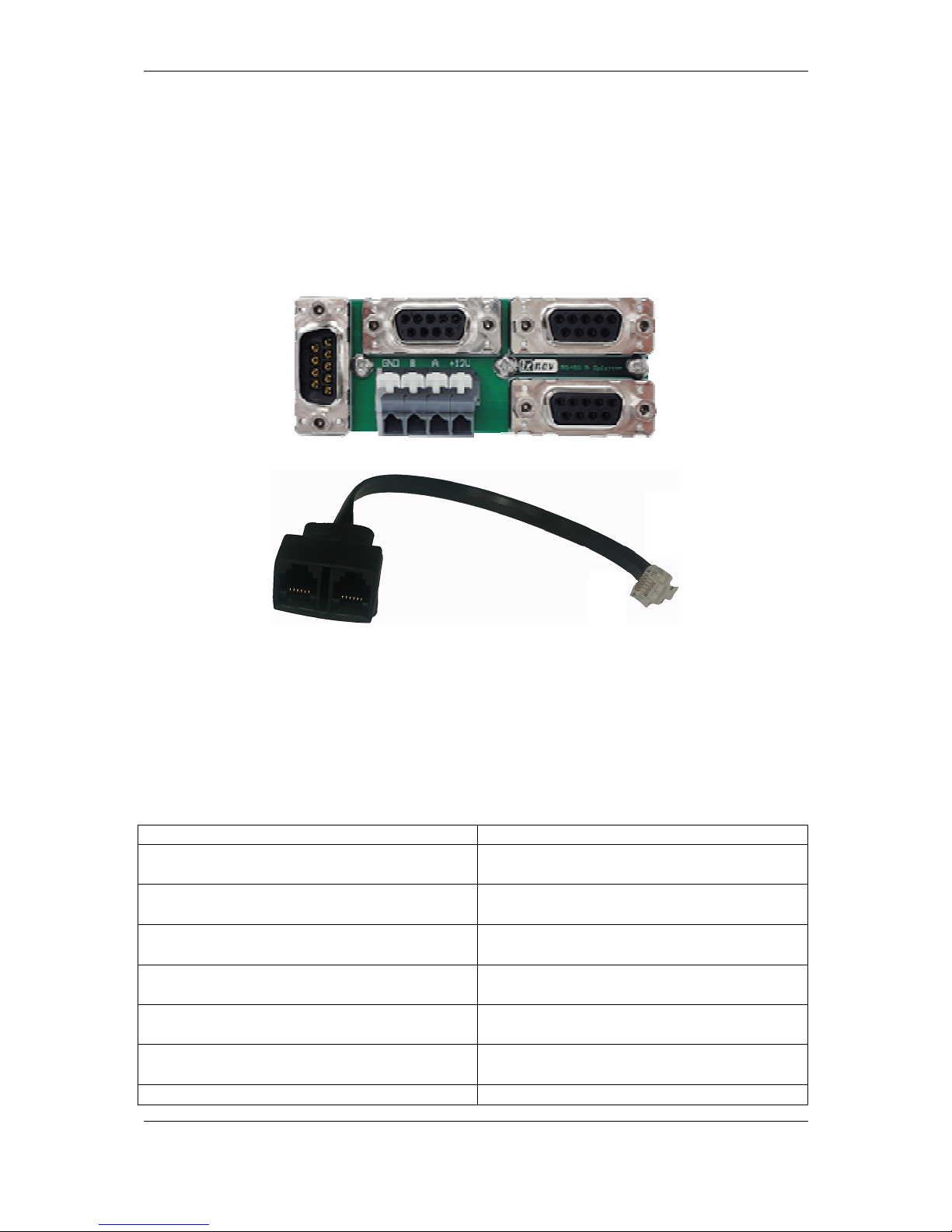
4.4 Splitters
LXNAV system can use two types of splitters
- RS485 splitter
- Flarm splitter
RS485 splitter is detailed described in chapters above.
Flarm splitter is used, when we want to connect more than one Flarm display to Flarm port.
4.5 Ethernet port
Almost all devices having Ethernet port which is in the moment used only for development
purposes.
4.6 Available Cables and Harnesses
Cable Part Number
Description
Connection cable NANO power/V7PDA - OUDIE
Order Nr.:CC-NP-OUDIE1
Cable
for connection between
O
udie and
PDA port
Connection cable NANO power/V7PDA
-
standard RS232
Order Nr.:CC-NP-232
Cable for connection between PDA port and
standard RS232 (DB9) connector
Connection cable NANO power/V7PDA
- IPAQ
38xx
Order Nr.:CC-NP-38
Cable
for connection between
PDA and
IPAQ with 38xx family connector
Connection cable NANO power/V7PDA
- PNA
V2, IPAQ 31x
Order Nr.:CC-NP-IPAQ310
Cable
for connection between PDA and
IPAQ with 310 family connector
Connection cable NANO power/V7PDA
-
V7/LX16x/LX16xx
Order Nr.:CC-NP-LX
Cable
fo
r connection between PDA and
LX
device with standard RJ11 port
Connection cable NANO power/V7PDA
-
Lx7xxx
Order Nr.:CC-NP-IGC
Cable for connection between PDA and LX
device with standard IGC RJ11 port
Connection cable NANO power/V7PDA
-
Cable
for connection between PDA and LX
Page 16

Overview of the system Version 1.0, June 2015
Page 16 of 65
Butterfly Connect
Order Nr.:CC-NP-BFC
device with
butterfly connect
Cable Digital Unit (for LX90
xx
/LX80
xx
)
Order
Nr.:du-ca
Main unit harness
Cable Vario Unit (for V5/V9
/V80/V8
)
Order Nr.:vu-
ca
Harness for vario units
Cable Double Seat (for LX90xx/LX80xx)
Order
Nr.:ds-ca
Harness for repeater units, includes 4m
RS485 cable
Cable USB or USB
-
D
Order Nr.: usb-ca
Harness for old types of vario units
Cable RS485 extension cable (4m)
Order Nr.: 485-
4m-ca
Extension cable for connection to
the rear
repeater unit
Cable RS485 bridge (30cm)
Order Nr.: 485-bridge-ca
RS485 bridge cable to bri
d
ge two RS485
splitters
Cable Instrument panel (5P) – PC
Order Nr.: lx5pc-ca
PC communication cable with rounded 5pin
connector. Used for RS232 communication
between PC and main unit. It can be used
also for Flarm firmware update, if update
via DS card is not successful
Cable LX8000/8080/9000 (5P) – FLARM (RJ11)
Order Nr.: lx5flarm-ca
Serial cable for external
Flarm
connection
between rounded 5pin connector and
standard Flarm RJ11 plug, including power
supply.
Cable LX8000/8080/9000 (5P)
PowerFLARM(RJ45)
Order Nr.:lx5PF-ca
Serial cable for external
PowerFLARM
connection between rounded 5pin
connector and standard Flarm RJ45 plug,
including power supply.
Cable LX8000/8080/9000 (5P) – PowerFLARM
Core (DB9)
Order Nr.:lx5pfcore-ca
Serial cable for external
PowerFLARM
connection between rounded 5pin
connector and standard DB9 plug for Power
Flarm Core including power supply.
Cable Flarm (RJ11) FlarmView/
FlarmL
ED
(RJ11)
(cca. 3.5m) Order Nr.:FlarmView3.5m-ca
Standard cable for Flarm displays 3.5m long
Cable Flarm (RJ11) FlarmView/FlarmLED(RJ11)
(cca. 40cm) Order Nr.:FlarmView-ca
Standard cable for
Flarm
displays 40cm
long
Cable PowerFLARM (RJ45)
FlarmView/FlarmLED(RJ11)
(cca. 40cm) Order
Nr.:FlarmViewPF-ca
Standard cable for
Flarm
displays 40cm
long on one side with RJ45 (PowerFLARM)
and another side with RJ11 (FlarmView)
Cable LX9000 TRX1090
Order Nr.:lx9000-TRX-ca (lx5pf-
ca + FlarmView-ca)
This is a cable set to connect ADSB receiver
Page 17
Overview of the system Version 1.0, June 2015
Page 17 of 65
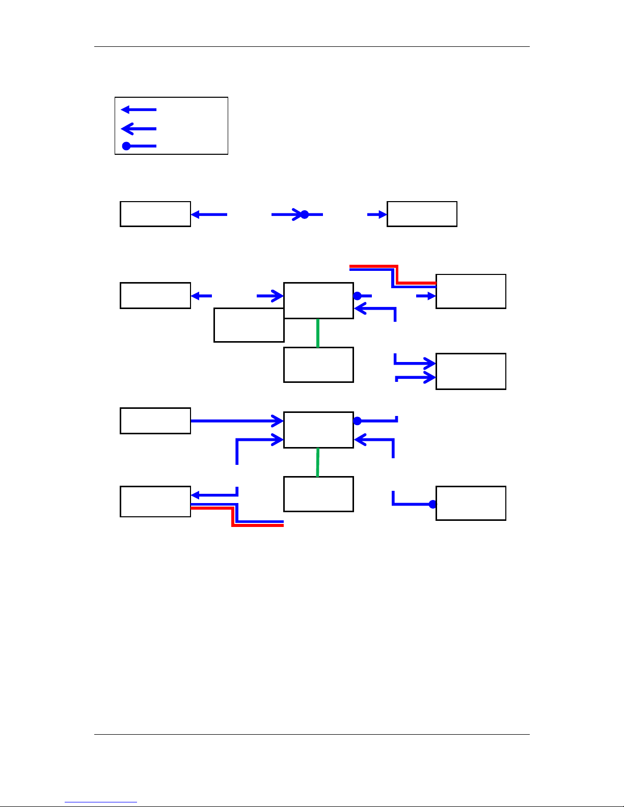
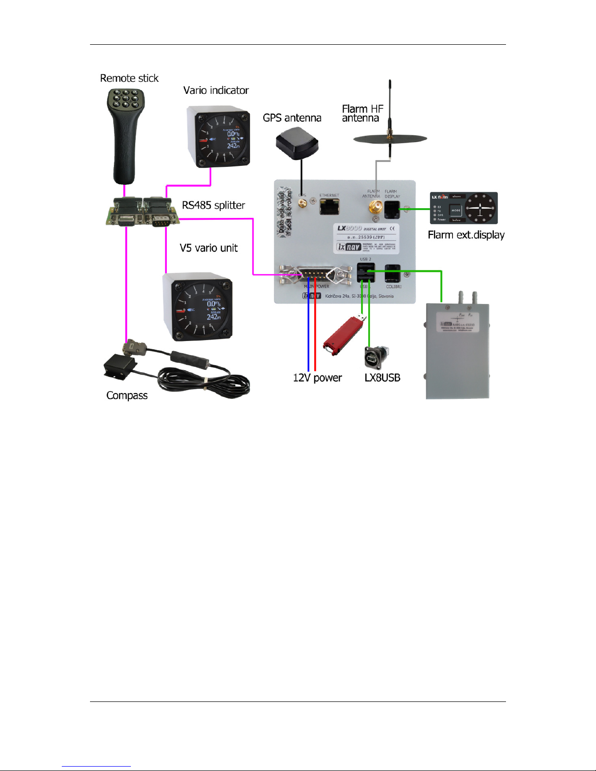
4.7 Examples of systems
Basic installation
More complex installation
DB15 Male
DB9 Female
DB9 Male
RS485
splitter
RS485
splitter
RS485
4m
MOP
sensor
Vario
indicator
RS48
5
MOP
Remote
stick 1
Flap sensor
LX90xxD
DS-CA RS485
Bridge
Radio
Bridge
Remote
stick 2
LX90xx Vario
VU-CA DU-CA
Vario
VU-CA
LX90xx
DU-CA
Power
Power
Page 18
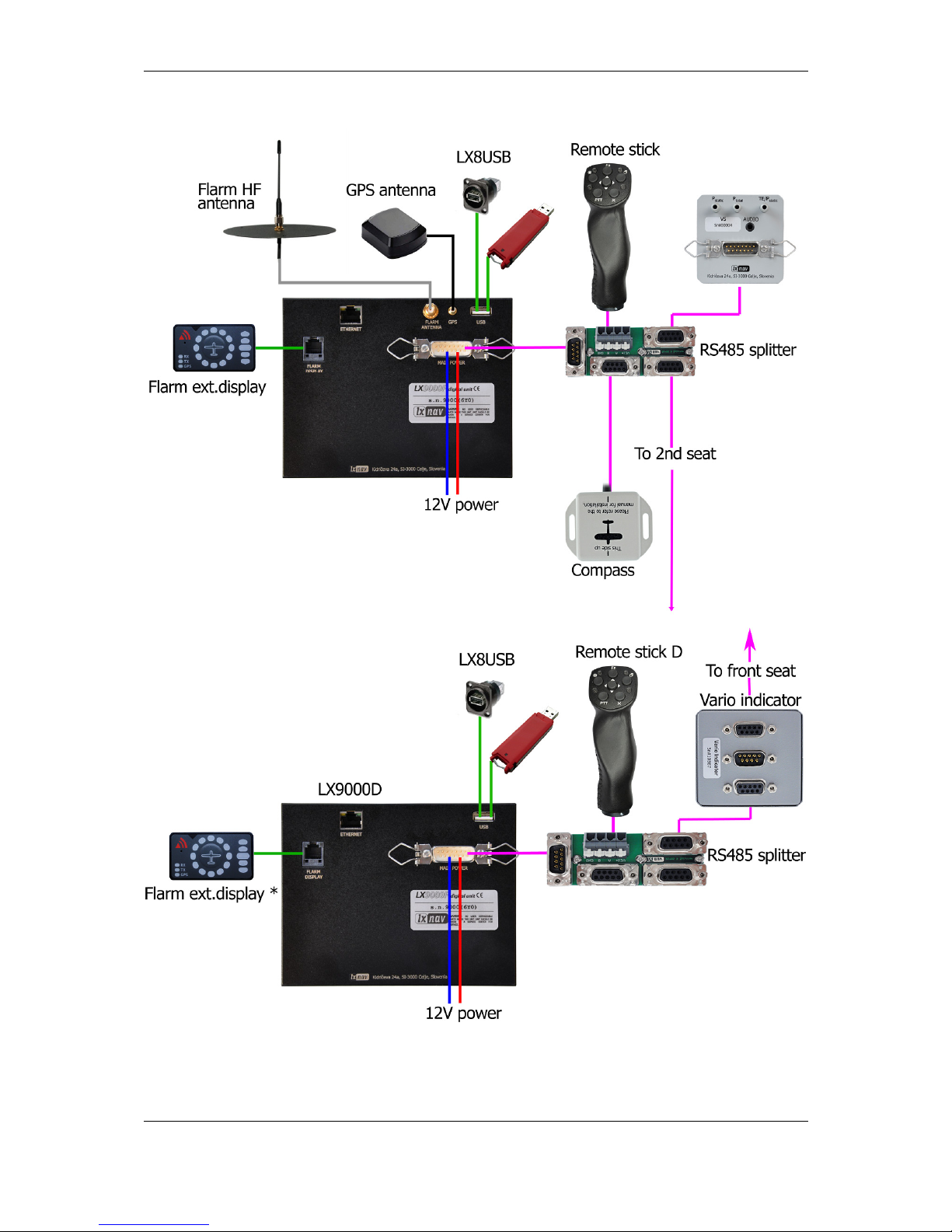
Overview of the system Version 1.0, June 2015
Page 18 of 65
General connection options
* This function may not work on older types of LX9000D
Page 19
Overview of the system Version 1.0, June 2015
Page 19 of 65
Page 20
Installation and Configuration Version 1.0, June 2015
Page 20 of 65
5 Installation and Configuration
5.1 Main unit and repeater unit
Before cutting out the panel, the whole cutting plan of the panel, including all indicators,
must be prepared. Next figure shows the cut-outs for the all types of the units that can be
installed into the panel.
Prepare the cut-out in the instrument panel according to the drilling template. Position the
Main display unit in the cut-out in the instrument panel. Tighten the main display unit with
attached 2.5 mm screws.
When installing the main display unit (LX90xx, LX8000) it is not necessary to
remove the rotary knobs. To install LX8080, is necessary to remove rotary knobs.
Position the main unit in the cut-out in the instrument panel. Tighten the main digital unit
with attached 2.5 mm screws.
When installing the LX8000, LX90xx it is not necessary to remove the rotary
knobs. Only by LX8080 is necessary to remove rotary knobs.
For LX8080 please remove the press
-
in covers from the four main rotary switches
on the LX8080. While holding the knobs, slacken t
he screws with a screwdriver.
Now the knobs can be removed (never use power to remove the knobs, you can
damage rotary switches). Remove the four M6 screws. Position the LX8080 in the
cut-out in the instrument panel. Tighten the LX8080. Tighten the knobs and fix
the covers
5.1.1 Installation of Options
All options except AHRS (LX8000D, LX8080D, Remote Control, Compass Module &
secondary vario indicators) are prepared to be connected to the RS485 system bus by use of
RS485 splitting units. Installation of any option is plug-and-play and therefore requires only
mechanical installation work. The LX8000 digital unit also powers all devices connected to
the bus. An automatic fuse built into the LX8000 digital unit prevents damage to the digital
unit should a short circuit in the wiring or in some attached device occurs.
Page 21

Installation and Configuration Version 1.0, June 2015
Page 21 of 65
5.1.2 Cut-outs
5.1.2.1 Lx9000 cut-out
Drawing is not to scale
Page 22

Installation and Configuration Version 1.0, June 2015
Page 22 of 65
5.1.2.2 Lx9070 cut-out
Drawing is not to scale
Page 23

Installation and Configuration Version 1.0, June 2015
Page 23 of 65
5.1.2.3 Lx9050 cut-out
Drawing is not to scale
5.1.2.4 Lx8080 cut-out
Drawing is not to scale
Page 24

Installation and Configuration Version 1.0, June 2015
Page 24 of 65
5.1.2.5 Lx8000 cut-out
Drawing is not to scale
Page 25

Installation and Configuration Version 1.0, June 2015
Page 25 of 65
5.1.3 Dimensions
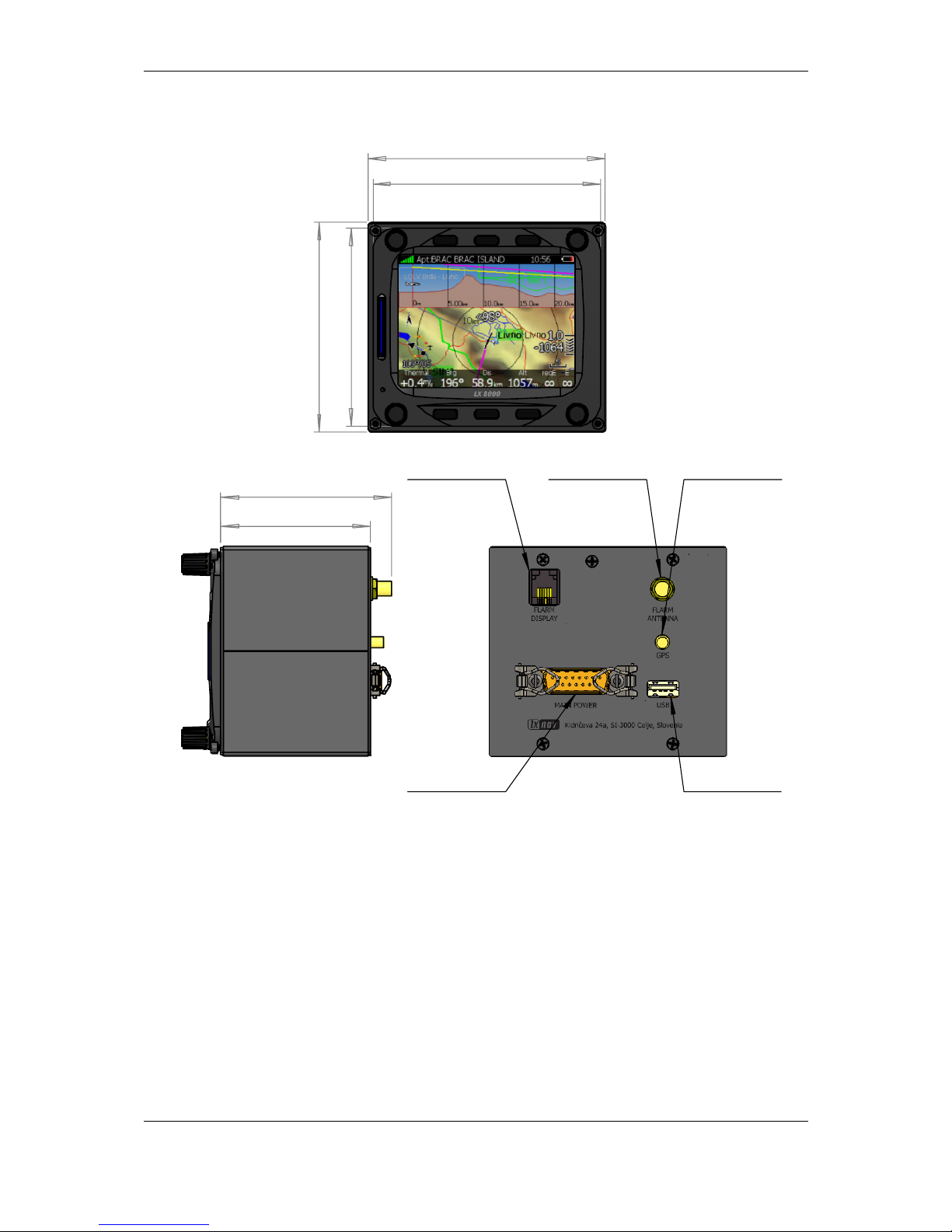
5.1.3.1 LX9000 dimensions
113
145,18
107
139
37,11
46,08
Flarm port
GPS antenna
Flarm antenna
USB port
Main port
Page 26
Installation and Configuration Version 1.0, June 2015
Page 26 of 65
5.1.3.2 LX9070 dimensions
113,50
180,70
174,70
107
46,08
37,11
Flarm port
GPS antenna
Flarm antenna
USB port
Main port
Page 27
Installation and Configuration Version 1.0, June 2015
Page 27 of 65
5.1.3.3 LX9050 dimensions
83
136
130
77
71,05
61,57
Flarm port
GPS antenna
Flarm antenna
USB port
Main port
PDA port
Page 28

Installation and Configuration Version 1.0, June 2015
Page 28 of 65
5.1.3.4 LX8080 dimensions
82
82
63
63
R
3
9
,
8
5
68,35
59,61
Page 29
Installation and Configuration Version 1.0, June 2015
Page 29 of 65
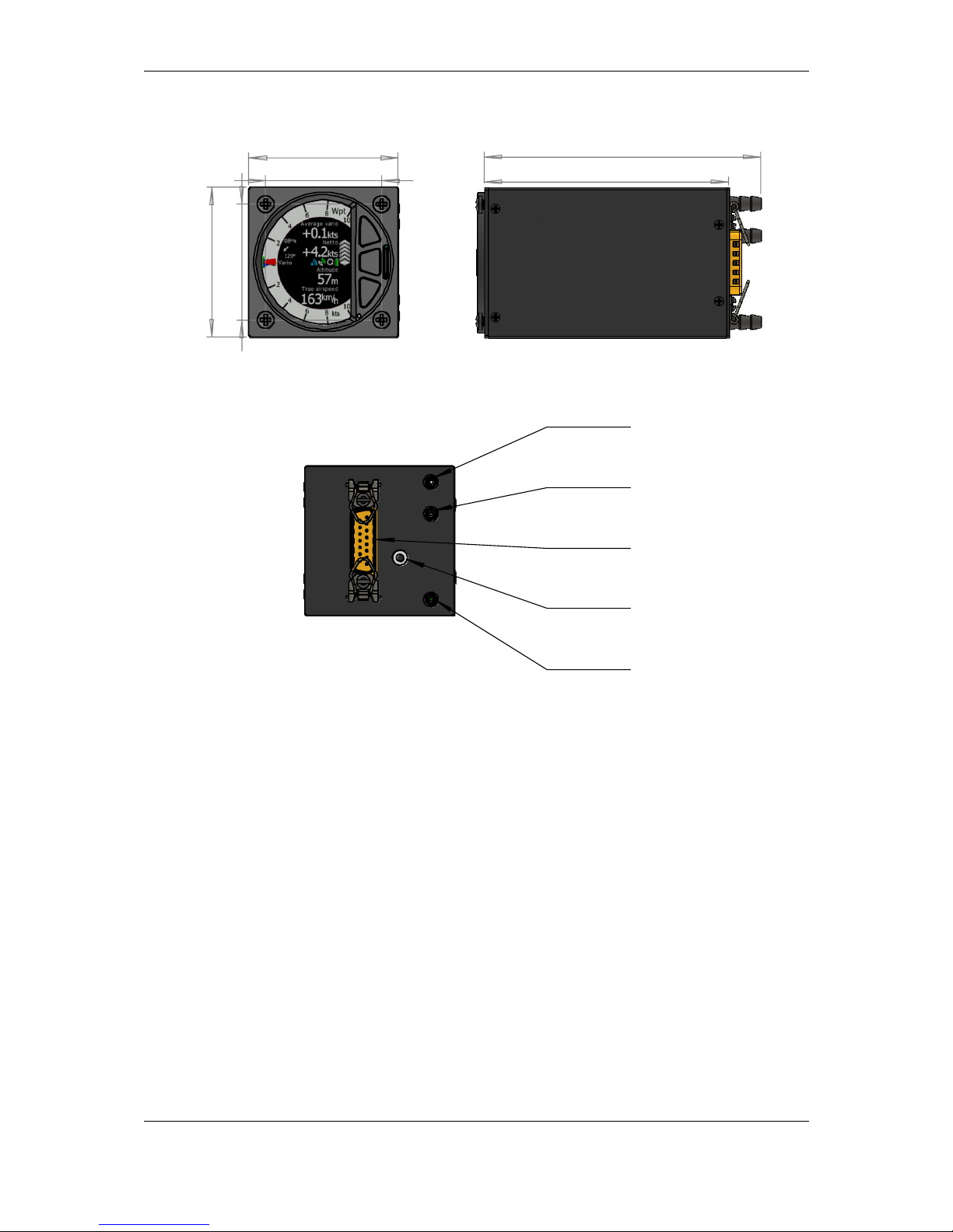
5.1.3.5 LX8000 dimensions
69,85
61,11
97
93
85,60
81
Page 30

Installation and Configuration Version 1.0, June 2015
Page 30 of 65
5.1.3.6 V5, V9 dimensions
93,51
107,01
61
61
23,58
13,50
15
13,50
52
47,38
47,38
R56,30
Page 31
Installation and Configuration Version 1.0, June 2015
Page 31 of 65
5.1.3.7 V8 dimensions
61
47,38
61
47,38
112,90
99,70
Page 32

Installation and Configuration Version 1.0, June 2015
Page 32 of 65
5.1.3.8 V80 dimensions
80,20
80,90
63
63
131,65
148,52
5.1.3.9 I5, I8 dimensions
TBD
5.1.3.10 I80 dimensions
TBD
Page 33

Installation and Configuration Version 1.0, June 2015
Page 33 of 65
5.1.1 Ports
5.1.1.1 LX9000
5.1.1.2 LX9050
GPS antenna
Flarm HF
antenna
Network connector
DO NOT USE IT!
Flarm external
indicators, splitters
USB memory stick
Main power supply
(LX9000DU wiring)
Flarm external
indicators, splitters
PDA port
Flarm HF antenna
GPS antenna
USB memory s
tick Main power supply
(LX9000DU wiring)
Page 34

Installation and Configuration Version 1.0, June 2015
Page 34 of 65
5.1.1.3 LX9050 simple
5.1.2 LX8000 Digital unit
PDA port
GPS input port
USB memory stick
Main power supply
(LX9000DU wiring)
GPS antenna
Network connector
DO NOT USE IT!
Flarm HF
antenna
Flarm external
indicators, splitters
USB memory sticks
Connector to USB1 port
Colibri or any other IGC
Flight recorder
Main power supply
(LX8000DU wiring)
Page 35

Installation and Configuration Version 1.0, June 2015
Page 35 of 65
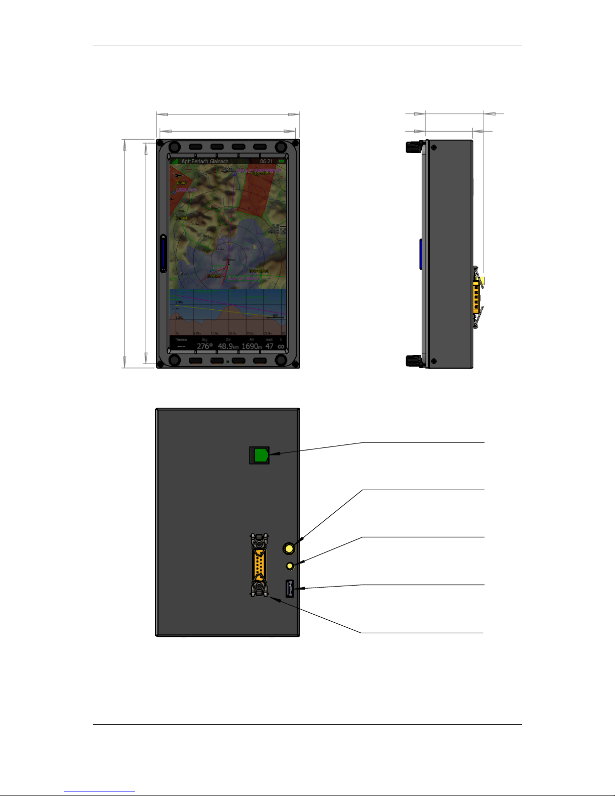
5.1.3 LX8000 Digital unit Version 2
5.1.4 LX8080 Digital unit
GPS antenna
Flarm HF
antenna
PDA port
Read manual
Flarm external
indicators, splitters
USB memory stick
Main power supply
(DU wiring)
GPS antenna
Flarm HF
antenna
Flarm external
indicators, splitters
USB memory sticks
Connector to USB1 port
Main power supply
(LX8080DU wiring)
Page 36

Installation and Configuration Version 1.0, June 2015
Page 36 of 65
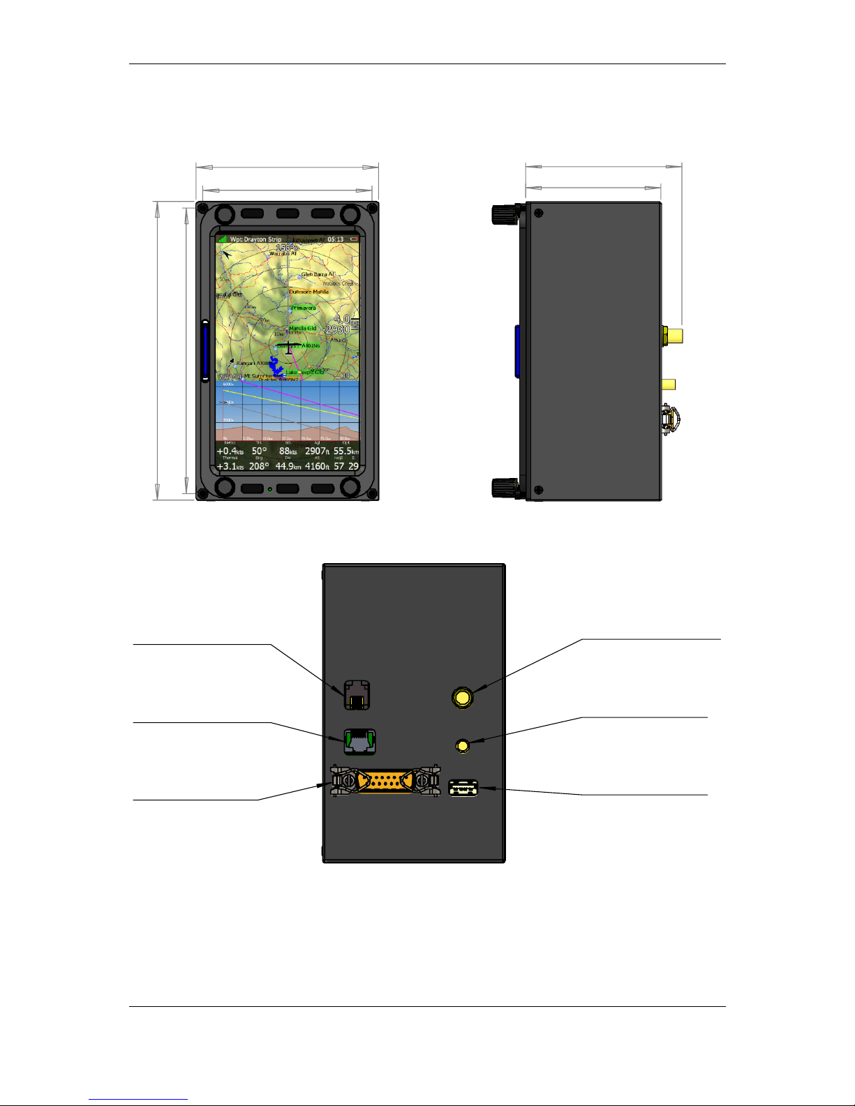
5.1.5 LX8080 Digital unit Version 2
5.1.6 LX8080 Digital unit Simple Version
GPS antenna
Flarm HF
antenna
Flarm external
indicators, splitters
PDA port
Read manual
USB memory stic
ks
Connector to USB1 port
Main power supply
(LX8080DU wiring)
GPS port
Read manual
PDA port
Read manual
USB memory sticks
Connector to USB1 port
Main power supply
(LX8080DU wiring)
Page 37

Installation and Configuration Version 1.0, June 2015
Page 37 of 65
5.1.7 Flarm Port (for LX8000 Versions 1 – no 12V output)
LX8080 LX8000
1 2 3 4 5 6 6 5 4 3 2 1
Pin numbers
Pin number Description
1 open
2 3.3V DC (max 100mA)
3 GND
4 Flarm Data Out
5 Flarm Data In
6 Ground
5.1.7.1 Flarm port on LX9xxx
1 2 3 4 5 6
Pin numbers
Pin number Description
1 (output) 12V DC, to supply GPS
2 (output) 3.3V DC (max 100mA)
3 GND
4 Flarm Data Out
5 Flarm Data In
6 Ground
Page 38

Installation and Configuration Version 1.0, June 2015
Page 38 of 65
Flarm port can be also configured on newer types of LX9000D. It can be enabled
in Setup-NMEA Output with selecting FLARM
5.1.7.2 PDA port (RJ45
Newer types of units have also expansion port called PDA (RJ45). On this port can be
connected different types of PDA devices.
1 2 3 4 5 6 7 8 8 7 6 5 4 3 2 1
Pin numbers Pin numbers
Pin number Description
1,2 Ground
3 (output) Transmit from LXNAV RS232 (e.g. Computer, IPAQ38/39xx)
4 (input) Receive to LXNAV RS232 (e.g. Computer, IPAQ38/39xx)
5 (output) Transmit from LXNAV V7 LV-TTL (3.3V) (e.g. Oudie, HP302,
HP31x)
6 (input) Receive to LXNAV LV-TTL (3.3V) (e.g. Oudie, HP302, HP31x)
7,8 5V OUTPUT (maximum 1A)
RJ45 plug is NOT designed in accordance with IGC standard. It can be used only
with dedicated cable. Do not plug unknown cable to it as it may damage unit or
PDA port.
On PDA port can be connected following connection cables:
Device
Cable code
OUDIE
CC-NP-
OUDIE1
Generic RS232 with female DB9
CC-NP-
232 IPAQ 310/314
CC-NP-
IPAQ310
IPAQ 38/39xx/47xx
CC-NP-38
Page 39
Installation and Configuration Version 1.0, June 2015
Page 39 of 65
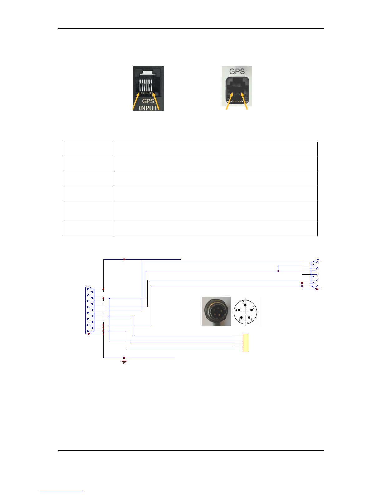
5.1.7.3 GPS ports (RJ11) only on Simple version
1 2 3 4 5 6 1 2 3 4 5 6
Pin numbers Pin numbers
Pin number Description
1 (output) 12V DC, to supply GPS
2,3 N.C.
4 (input) Receive to main display unit RS232 (e.g.: NANO power 232)
5 (output) Transmit from LXNAV main display unit RS232 (e.g.: NANO power
232)
6 Ground
5.1.1 Wirings
1
6
2
7
3
8
4
9
5
SUBD15 Connector / female
LX9000 DIGITAL UNIT
+12V DC OUT
white
red
shield
black
yellow
GND
+12V
B
A
RS485 - OUT
SUBD9 / female
GND
LABEL: +12V DC IN
1
9
2
10
3
11
4
12
5
13
6
14
7
15
8
Data Out
Data In
B
A
1
2
3
4
5
BINDER 5Pin Male
PC-RS232C
09 0097 00 05
White - Data In
Black - Data Out
Shield GND
1
3
5
30 cm
50cm
Red +12V 2
GND
GND
GND
shield
shield
LABEL:RS232
LABEL:RS485
5.2 Connection and Functionality Check of All Peripheral Units
The main display unit is connected to 12 Volt power via the 15-pin SUB-D connector. The
main display unit, vario unit and other vario indicators are connected via the RS485 bus and
the connectors are labelled with “RS485” at each end.
Please ensure that both units are connected correctly before the first power on. The power
wires (red and blue) should be connected to the main display unit.
Page 40

Installation and Configuration Version 1.0, June 2015
Page 40 of 65
Even though there is an automatic fuse in the instrument it is VERY IMPORTANT
to use an external fuse (max. 3A). Power supply cables should use a minimum of
0.5 mm² AWG20 wires.
When main unit is connected to vario and other peripheral units, we can make functionality
test. After power up, vario unit should turn on. Other peripheral units have on visual
indication, so they will be tested on main unit.
5.2.1 Vario Unit
5.2.1.1 Connecting vario unit
Vario unit is connected to main unit through RS485 bus. SC cable is used for external switch,
for switching between climb and cruise mode. In case that SC is connected to flaps switch,
VP (vario priority) is connected to switch on stick. Inputs IN1...4 are used to connect to gear
switch, airbrakes, etc...
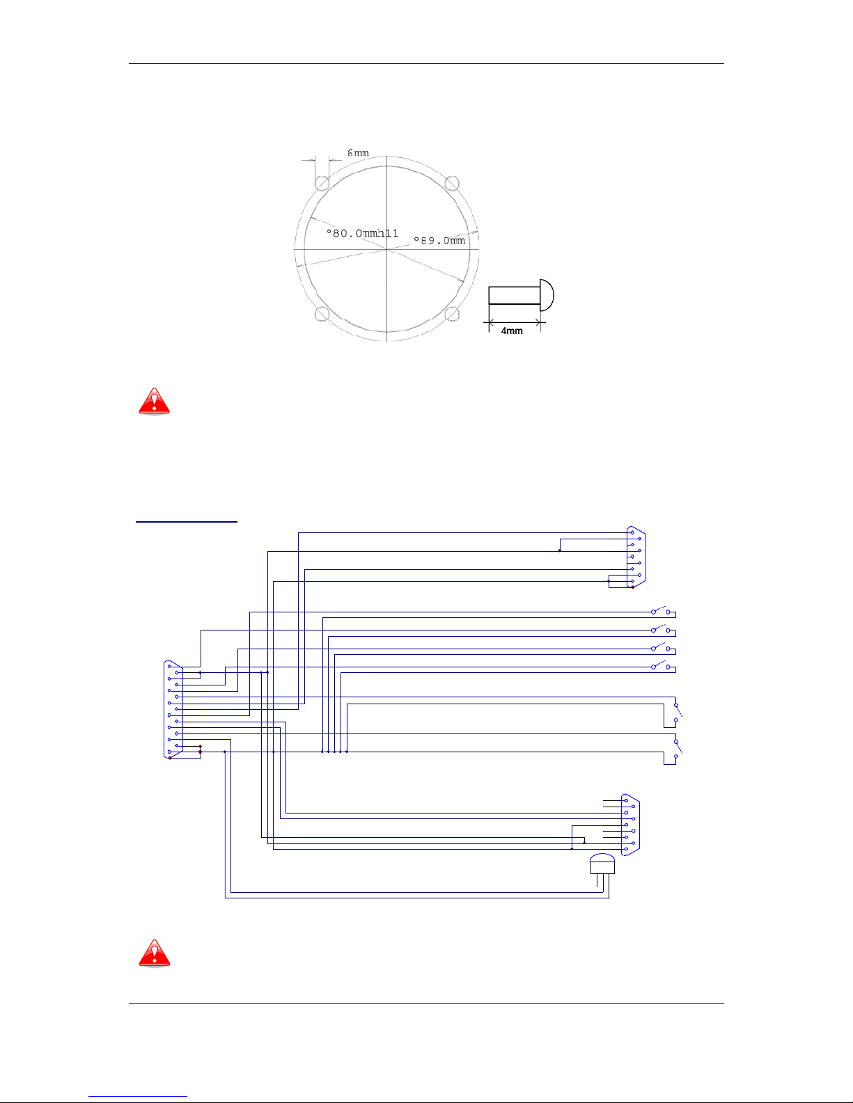
5.2.1.2 Cut-outs
5.2.1.2.1 Cut-out for V5 and V9
Drawing is not to scale
5.2.1.2.2 Cut-out for V8
Drawing is not to scale
Length of screw is limited to max 4mm!
Page 41
Installation and Configuration Version 1.0, June 2015
Page 41 of 65
5.2.1.2.3 Cut-out for V80
Drawing is not to scale
Length of screw is limited to max 4mm!
5.2.1.1 Wirings
5.2.1.1.1 V5 Ver1 wiring with CAN bus (discontinued)
1
6
7
4
9
5
SUBD15 Connector / female
SBOX
white
red
shield
black
yellow
GND
+12V
B
A
GND SHIELD
SC
1
9
2
10
3
11
4
12
5
13
6
14
7
15
8
B
A
SC switch
30 cm
30 cm
50 cm
V5 V1.0 Wiring
VP switch
VP
50 cm
(green)
(Brown)
OAT
1.5m
OAT
LABEL:OAT
LABEL: VARIO PRIORITY
LABEL:SC
LABEL:RS485
shield
Reserved for CAN BUS
SUBD9 / female
CAN H
CANH
CANL
INPUT2
INPUT1
INPUT3
INPUT4
12V IN
IN1
IN3
IN2
IN0
LABEL:IN-1
LABEL:IN-2
LABEL:IN-3
LABEL:IN-4
1
6
2
7
3
8
4
9
5
J3
CAN L
CAN GND
CAN GND
12V
LABEL: CAN BUS
50 cm
50 cm
50 cm
50 cm
1 2 3
GND
LM335Z
GND SHIELD
GND SHIELD
GND SHIELD
GND SHIELD
GND SHIELD
GND SHIELD
4 zilni tasker
RS485 - IN
SUBD9 / male
There is also CAN bus connector, which is prepared for future.
DO NOT CONNECT IT ANYWHERE
Page 42

Installation and Configuration Version 1.0, June 2015
Page 42 of 65
5.2.1.1.2 V5/V8/V9/V80 vario unit wiring
1
6
7
4
9
5
SUBD15 Connector / female
V5
white
red
shield
black
yellow
GND
+12V
B
A
GND SHIELD
SC
1
9
2
10
3
11
4
12
5
13
6
14
7
15
8
B
A
SC switch
30 cm
50 cm
VP switch
VP
50 cm
(green)
(Brown)
OAT
1.5m
OAT
LABEL:OAT
LABEL: VARIO PRIORITY
LABEL:SC
LABEL:RS485
(pusti olupljen pospajkan kabel)
shield
CANH
CANL
INPUT2 - AIRBRAKES
INPUT1 - GEAR
INPUT3 - WATER BALLAST - VALVE
INPUT4 - FREE
12V IN
IN1
IN3
IN2
IN0
LABEL:IN-1
LABEL:IN-2
LABEL:IN-3
LABEL:IN-4
Free
Closed, when valve is closed
Closed, when Airbrakes are closed
Closed, when gear is down
50 cm
50 cm
50 cm
50 cm
1 2 3
GND
LM335Z
GND SHIELD
GND SHIELD
GND SHIELD
GND SHIELD
GND SHIELD
GND SHIELD
RS485 - IN
SUBD9 / male
5.2.1.1.3 USB-D or Analog unit wiring (discontinued)
1
6
7
4
9
5
SUBD15 Connector / female
LX9000 VARIO UNIT
white
red
shield
black
yellow
GND
+12V
B
A
RS485 - IN
SPEAKER
SUBD9 / male
GND
+12V DC IN
SC
1
9
2
10
3
11
4
12
5
13
6
14
7
15
8
Data Out
Data In
B
A
RCA Jack Receptacle (CHINCH/Female)
SC switch
Speaker
30 cm
30 cm
50 cm
LABEL:AUDIO OUT
LX 9000 VARIO UNIT Wiring
VP switch
VP
50 cm
(green)
(Brown)
DS1820 OAT
1.5m
OAT
LABEL:OAT
LABEL: VARIO PRIORITY
LABEL:SC
LABEL:RS485
shield
shield
5.2.1.2 Connection to the bus
Vario is connected to main instrument via RS485 bus directly or via RS485 splitter, if there
will be more units connected to the system.
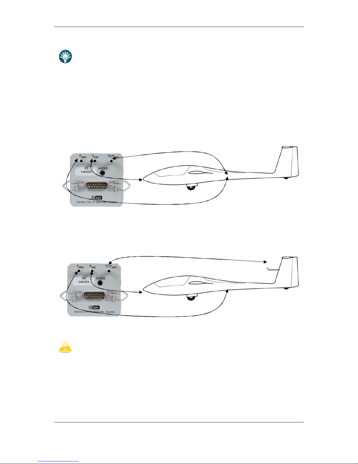
5.2.1.3 Pneumatics
Please carefully connect tubes to the right port of vario unit.
Three pressure connectors are fitted to the back of the vario unit. A label shows their
functions.
Page 43
Installation and Configuration Version 1.0, June 2015
Page 43 of 65
V9 vario has same functionality than V5, the only difference is, that has built in
inertial platform (AHRS)
• P
static
means static pressure connector.
• P
total
means pitot or total pressure connector.
• TE means total energy TE connector.
If the unit is to be configured for electronic TE compensation the connections are as follows:
• P
static
Static
• P
total
Pitot or Total pressure
• TE/P
static
Static
If the unit is to be configured for pneumatic TE compensation using a TE tube, then the
connections are:
• TE/P
static
TE tube
• P
static
Static
• P
total
Pitot or Total pressure
If the P
total
and Static are connected the wrong way around there will be no
integrator reading (average climb) during the flight.
The main display unit is connected to 12 Volt power via the 15-pin SUB-D connector. The
main display unit, vario unit and other vario indicators are connected via the RS485 bus and
the connectors are labelled with “
RS485
” at each end.
Please ensure that both units are connected correctly before the first power on. The power
wires (red and blue) should be connected to the main display unit.
Page 44

Installation and Configuration Version 1.0, June 2015
Page 44 of 65
It is VERY IMPORTANT to use an external fuse (max. 3A). Power supply cables
should use a minimum of 0.5 mm² wires.
5.2.1.4 Audio
Audio speaker is plugged on vario unit Audio port. Audio port has standard 3.5mm phonojack (mono).
5.2.1.5 Inputs
V9, V8, V80 and V5 variometers are having 6 programmable digital inputs. They are labelled
with SC, VP, IN1, IN2, IN3 and IN4 on V5/V9 cable-set. In the moment digital input can
represent the state of following actions:
• SC
• Vario priority
• Gear down and lock
• Airbrakes open
• Water ballast open
• Mute vario sound
Digital input shall be wired via switch to ground and it shall open or close, when selected
action is performed. A green light will light.
If necessary, check
Invert
check box, to reverse the operation of digital input.
Once digital inputs are connected the system will warn pilot, if airbrakes are open on takeoff and when gear is not locked prior to landing.
Page 45

Installation and Configuration Version 1.0, June 2015
Page 45 of 65
5.2.2 Installation of Options
All options (Rear Seat Device, Remote Control, Compass Module & secondary vario
indicators) are prepared to be connected to the RS485 system bus by use of RS485 splitting
units. Installation of any option is plug-and-play and therefore requires only mechanical
installation work. The main display unit also powers all devices connected to the bus. An
automatic fuse built into the main display unit prevents damage to the digital unit should a
short circuit in the wiring or in some attached device occurs.
5.2.2.1 Remote Sticks
LXNAV remote stick is connected to RS485 bus through RS485 splitter.
Be careful, that connect correct colour wire to pin, which is marked with same colour.
PTT wires are connected to radio, SC is connected to Speed to fly input of vario unit.
If you are installing remote stick into double seater gliders or aircraft, be careful.
Stick for rear seat is marked as DS. DS remote stick is programming to control
Page 46

Installation and Configuration Version 1.0, June 2015
Page 46 of 65
repeater unit, which is installed on 2
nd
seat.
5.2.2.2 Flarm
Mostly Flarm is built inside main display unit. In this case we need to connect Flarm
antenna to the connector marked with Flarm.
Flarm antenna connector is SMA type. Normally we supply dipole antenna on approx. 1m
long cable.
For good Flarm reception, Flarm antenna must be positioned vertically, as far as possible
from metal parts, cables and instruments.
We had very good experience installing Flarm antenna in the tail of the glider.
5.2.2.3 External Flarm or Power Flarm
If main display unit has no internal Flarm, user has a possibility to connect to it external
Flarm or Power Flarm. All Flarm/Power Flarm items will be displayed on the navigation map,
with same functionality as is with built-in Flarm.
External Flarm/Power Flarm can be connected to the main display unit with
LX5FLARM
cable.
On main display unit side LX5FLARM is connected to 5 pin rounded connector. On the other
side of LX5FLARM cable is 6 pin standard IGC RJ12 plug connector, which is plugged into
Flarm/Power Flarm port.
Using improper type of cable may harm your display unit or Flarm/Power Flarm
units.
For connection to the power Flarm is prepared special cable LX5PF, with RJ45 on
Flarm side.
Page 47

Installation and Configuration Version 1.0, June 2015
Page 47 of 65
5.2.2.4 ADSB receiver
It is possible to connect to the system with build in Flarm an ADSB-receiver TRX-1090 from
Garrecht Avionics (www.garrecht.com).
TRX-1090 can only be connected to the system with integrated Flarm option.
The TRX-1090 has been developed to upgrade the FLARM collision avoidance system, which
is installed in more than 13.000 aircraft worldwide. The unit will be connected between
FLARM and a FLARM compatible external display unit and will simultaneously show FLARM
targets and Mode-S transponder equipped aircraft with ADS-B output capability. The
presence of transponder equipped aircraft not broadcasting ADS-B output will be detected
and indicated on the connected display as a non-directional target. The TRX-1090 comes
with a high sensitivity low distortion receiver unit and a highly complex and powerful signal
processing unit with multi-level error correction algorithms to provide data with a very high
accuracy.
5.2.2.4.1 TRX tool
Using the TRX-Tool program you should configure also TRX-1090 to be used together with
the system. TRX-Tool can be downloaded on the web (http://www.garrecht.com) under
Support/Downloads/Software section. Run the TRX-Tool program and connect the TRX1090 to PC using a USB cable. Select Port4 tab and change connected equipment to LX8000
(or FLARM without RX line connected).
Page 48

Installation and Configuration Version 1.0, June 2015
Page 48 of 65
Select Port2 tab and change
Baud rate
to 19200bps.
The LX90xx system and TRX-1090 are now ready for operation. On the info page you
should see the TX sign and number of received objects.
Page 49

Installation and Configuration Version 1.0, June 2015
Page 49 of 65
5.2.2.4.2 Connecting TRX-1090 to the system
Disconnect cable from the Flarm external display and connect the free cable to Port4 on the
TRX-1090. Use the LX9000-TRX cable (not-included, must be ordered separately) and
connect it between PORT2 and PC port on the main display unit.
On the main display unit go to the setup menu and choose Hardware->Flarm menu item.
Change mode to
Ext. (PC)
.
Port on LX9000 Cable Port on TRX 1090
LX9000 FLARM -> via cable (Flarm-TRX1090) -> TRX Port4 (Flarm original or
compatible)
LX9000PC (5pin
rounded
connector)
<- via cable (TRX LX9000) <- TRX Port2 (Flarm Compatible
display, set to 19200)
Page 50

Installation and Configuration Version 1.0, June 2015
Page 50 of 65
5.2.2.5 Additional indicators
Indicators are coupled on RS485 bus via supplied RS3485 cables and additional RS485
splitters.
5.2.2.6 Flap Sensor
Flap sensor is also communicating with main system through RS485 bus. Installation of flap
sensor may be complicated for particular gliders. Please contact glider manufacturer for
more details.
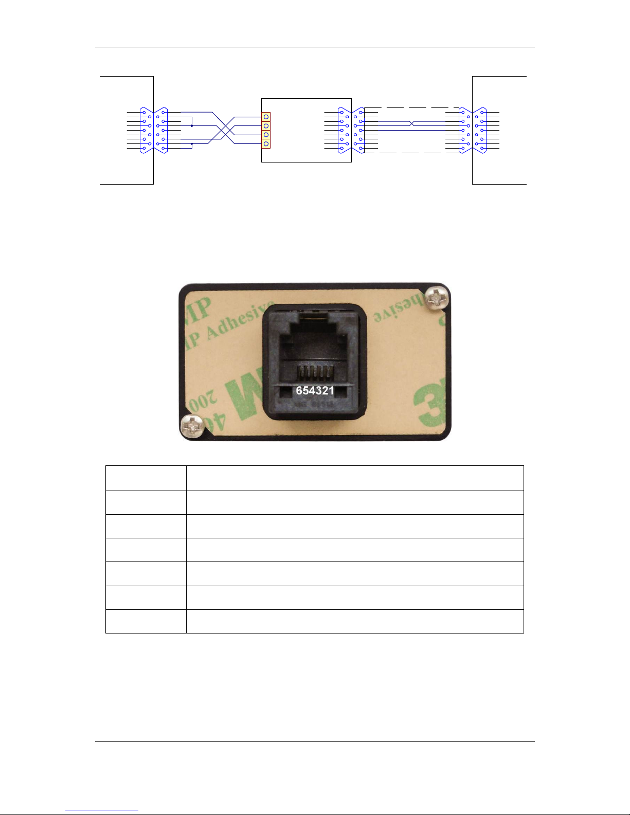
5.2.2.7 485 to 232 bridge
LXNAV RS485toRs232 Bridge (Bridge) is connected to RS485 bus through RS485 splitter DB9
connector. RS485 splitter is not part of package. If you don’t have spare port on RS485
splitter, you must order it.
5.2.2.7.1 Installation
RS485 splitter needs small modification, the Bridge can be fitted. It's necessary to remove
two HEX screws, where Bridge will be connected and screw bask two spring locks that are in
package.
After that fixing Bridge to RS485 splitter will be very easy.
On the other side of Bridge is RJ12 connector with standard IGC/FLARM pinout
1 2 3 4 5 6
Pin numbers
Pin number Description
1 (output) 12V DC, to supply GPS
2 3.3V DC (max 100mA)
3 GND
4 Flarm Data Out
Page 51

Installation and Configuration Version 1.0, June 2015
Page 51 of 65
5 Flarm Data In
6 Ground
By default Bridge is programmed to stream NMEA data on 4800bps. It streams standard
GPS and Flarm data. 485 to 232 bridges can be configured as NMEA Bridge, Radio Bridge or
Transponder Bridge.
5.2.2.7.2 NMEA Bridge
NMEA Bridge has been designed to expand number of NMEA ports in the system. It can be
used as classic NMEA output for PDA device, to feed Mode-S transponder with NMEA.
5.2.2.7.3 Radio Bridge
Radio Bridge is same part of hardware as NMEA Bridge. On the main unit it can be
configured as Radio Bridge, which can communicate with following radios.
DEVICE TYPE DEVICE NAME
TESTED WITH PHYSICAL
DEVICE?
NOTES
RADIO
BECKER CM4201
NO Physical device needed to test.
RADIO
FUNKWERK ATR833
YES
RADIO
DITTEL KRT2
YES
RADIO
GARMIN SL40
NO Physical device needed to test.
RADIO
BECKER
- AR6201
- RT6201
- RCU6201
- AR6203
NO
Physical device needed to test.
(18.2.2015)
5.2.2.7.4 Transponder Bridge
Transponder Bridge is same part of hardware as NMEA Bridge. On the main unit it can be
configured as Transponder Bridge, which can communicate with following radios.
DEVICE TYPE DEVICE NAME
TESTED WITH
PHYSICAL DEVICE?
NOTES
TRANSPONDER
BECKER BXP6402
YES
TRANSPONDER
FUNKWERK
TRT800
NO
The status interface is a TX
-
only connection, not possible
to control it.
TRANSPONDER TRIG TT 21/22 YES
Page 52

Installation and Configuration Version 1.0, June 2015
Page 52 of 65
5.2.2.7.5 Wirings for radio and Transponder Bridge
5.2.2.7.5.1 Radios
5.2.2.7.5.1.1 Funkwerk ATR833
5.2.2.7.5.1.2 Dittel KRT2
5.2.2.7.5.2 Transponders
5.2.2.7.5.2.1 Becker BXP6402
Page 53

Installation and Configuration Version 1.0, June 2015
Page 53 of 65
5.2.2.7.5.2.2 Trig TT 21/22
5.2.2.8 Wi-Fi___33
Wi-Fi___33 dongle must be plugged in USB port. Wi-Fi___33 will be operative, when unit
will have enabled that option and wireless network is available.
5.2.2.9 Compass
Compass module must be connected to RS485 bus. It must be installed to the place where
is no strong magnetic fields (Irons or ferromagnetic materials), cables with AC current or not
constant DC currents.
When installing magnetic compass use screws made of non-ferromagnetic
materials (plastic or brass)
Page 54

Installation and Configuration Version 1.0, June 2015
Page 54 of 65
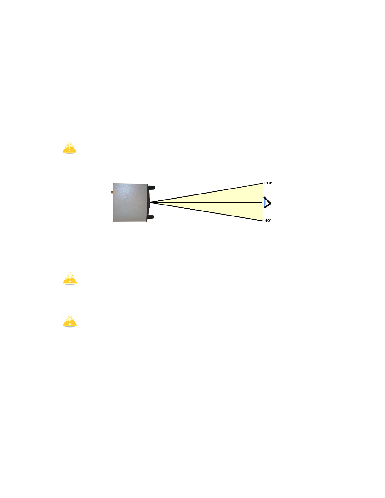
Orientation of compass module marked on housing as on picture above.
5.2.2.10 AHRS
AHRS hardware is built in each V9 unit, to see artificial horizon, is necessary to activate that
option.
It’s recommended, to install V9 vario as horizontally as possible. Small corrections
can be adjusted with pitch correction.
5.2.2.11 FES Bridge
FES Bridge is device which connects together FCU CAN bus and system RS485 bus.
Indication gauges can be created with LXStyler or LAYOUT function. On RS485 side is the
easiest way to connect on RS485 splitter on Remote Stick pins (parallel). Just connect
correct colour to the right pin. On the other side it should be connected to CAN bus (DB9)
of FCU. On this side 3 wires need to be soldered to the right pins.
1
6
2
7
3
8
4
9
5
DB9 Female
1
6
2
7
3
8
4
9
5
DB9 Female
1
6
2
7
3
8
4
9
5
DB9 Male
FCU
CAN Female-Female
CAN_HCAN_L
CAN_H CAN_L
GNDGND
No additional termination resistors needed
1
6
2
7
3
8
4
9
5
DB9 Male
FES bridge
1
6
2
7
3
8
4
9
5
DB9 Male
1
6
2
7
3
8
4
9
5
DB9 Female
LX9000
RS485-B
RS485-A
or
RS485 Splitter
12V
GND
RS485-A
RS485-B
12V
GND
(view from top)
5.2.2.12 JDU Bridge
JDU Bridge is device which connects together JDU CAN bus and system RS485 bus.
Indication gauges can be created with LXStyler or LAYOUT function. On RS485 side is the
easiest way to connect on RS485 splitter on Remote Stick pins (parallel). Just connect
correct colour to the right pin. On the other side it should be connected to CAN bus (DB9)
of FCU. On this side 3 wires need to be soldered to the right pins.
Page 55
Installation and Configuration Version 1.0, June 2015
Page 55 of 65
1
6
2
7
3
8
4
9
5
DB9 Female
1
6
2
7
3
8
4
9
5
DB9 Female
1
6
2
7
3
8
4
9
5
DB9 Male
JDU
CAN Female-Female
CAN_HCAN_L
CAN_H CAN_L
GNDGND
No additional termination resistors needed
1
6
2
7
3
8
4
9
5
DB9 Male
JDU bridge
(view from top)
1
6
2
7
3
8
4
9
5
DB9 Male
1
6
2
7
3
8
4
9
5
DB9 Female
LX9000
RS485-B
RS485-A
or
RS485 Splitter
12V
GND
RS485-A
RS485-B
12V
GND
5.2.2.13 FlarmLED display
FlarmLED display is used to display Flarm warnings. It must be installed on visible place,
that pilot can immediately see collision warning. Flarm led is connected via standard Flarm
cable with RJ12 (6 pin connectors). It is supplied over 3V pin
5.2.2.13.1 Pinout
Pin number Description
1 N.C.
2 (output) Transmit from LXNAV FLARM LED RS232 Level
3 (input) Receive to LXNAV FLARM LED RS232 Level
4 Ground
5 3.3V power supply (input)
6 N.C.
Page 56

Installation and Configuration Version 1.0, June 2015
Page 56 of 65
5.2.2.13.2 Cut-out
Front view
Drawing is not to scale
5.2.2.14 FlarmView display
FlarmView is similar display like FlarmLED, it has graphics display and provides to the pilot
more information, like Flarm radar screen and information about all visible targets. It must
be installed on visible place, where pilot can see collision warning immediately. FlarmView is
connected via standard Flarm cable with RJ12 (6 pin connectors). It is supplied over 12V
pin
5.2.2.14.1 Pinout
1 2 3 4 5 6
Pin numbers
Pin number Description
1 (Power input) 12VDC (On version 2)
2 (Power input) 3.3VDC (On version 1)
3 GND
4 (input) Data in RS232 – receive line
5 (output) Data out RS232 – transmit line
Page 57

Installation and Configuration Version 1.0, June 2015
Page 57 of 65
6 Ground
5.2.2.14.2 Cut-out
The LXNAV FlarmView cut-out is very simple. A square hole with dimensions 14mm x 15mm,
need to be cut.
Drawing is not to scale
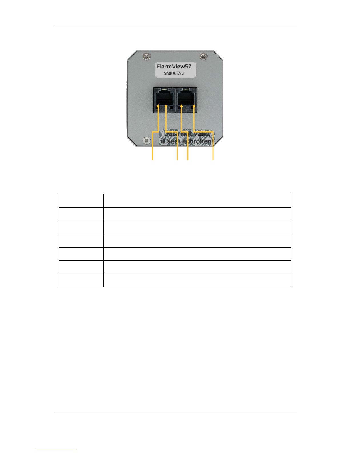
5.2.2.15 FlarmView57 display
FlarmView57 is same display like FlarmView, only different housing. FlarmView57 is
connected via standard Flarm cable with RJ12 (6 pin connectors). It is supplied over 12V
pin
5.2.2.15.1 Cut-out
The FlarmView57 is installed in one standard 57mm (2, 5’’) cut-out. If there is none, prepare
it according to the picture below.
Drawing is not to scale
Page 58
Installation and Configuration Version 1.0, June 2015
Page 58 of 65
5.2.2.15.2 Pinout
1 2 3 4 5 6 1 2 3 4 5 6
Pin numbers Pin numbers
Pin number Description
1 (Power input) 12VDC (On version 2)
2 (Power input) 3.3VDC (On version 1)
3 GND
4 (input) Data in RS232 – receive line
5 (output) Data out RS232 – transmit line
6 Ground
Page 59
Installation and Configuration Version 1.0, June 2015
Page 59 of 65
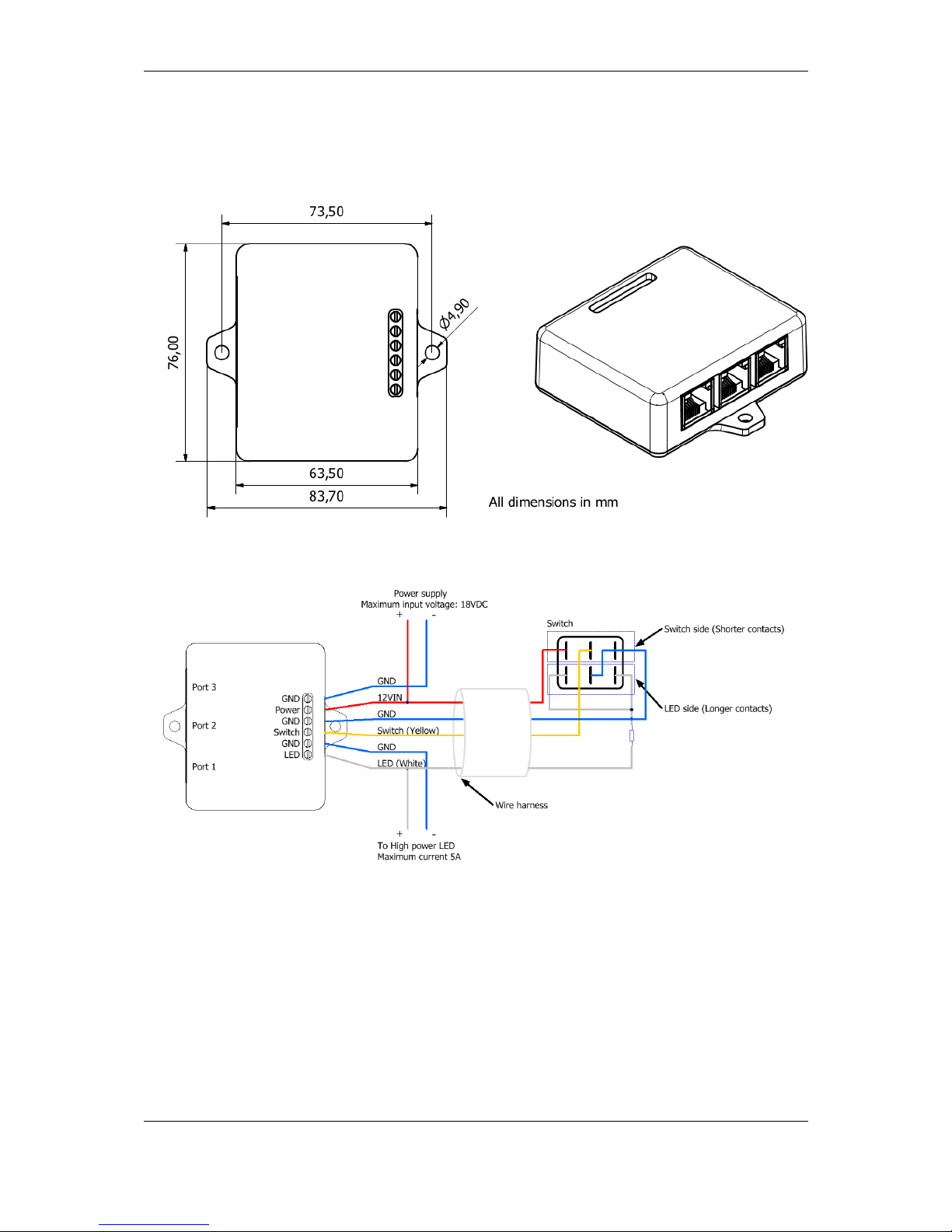
5.2.2.16 Flarm ACL
FlarmACL is a box which can switch on or off Anti Collision light. This switching can be
automatically or manually.
5.2.2.16.1 Wiring
Page 60

Version 1.0, June 2015
Page 60 of 65
5.2.2.16.2 Ports and Pinouts
FlarmACL connects together Pin 1 from Port 1-3, Pin 2 from Port 1-3, etc. Pin names are:
1- +12V
2- +12V
3- +3,3V (Flarm displays)
4- GND
5- Data Input (Output)
6- Data Output (Input)
7- GND
8- GND
5.2.2.17 Bluetooth module
LXNAV Bluetooth module is special device, which can be used only in combination with
LXNAV PDA port (RJ45). Connecting to other similar port will damage the unit.
Page 61

Firmware updates Version 1.0, June 2015
Page 61 of 65
6 Firmware updates
All firmware updates are performed entering password 89891 on the main unit. Next step is
to choose the firmware file. If main unit will detect right unit, firmware update will start.
In latest versions firmware for main unit includes also all firmwares for peripheral units.
Page 62

Troubleshooting Version 1.0, June 2015
Page 62 of 65
7 Troubleshooting
7.1 Export Diagnostic Files
Diagnostic file can be downloaded on main unit under Setup-About. If SD card is in the SD
socked, user can copy diagnostic file to SD card. If Wi-Fi module is plugged in and wireless
network is available, user can send this file over email directly to LXNAV.
Page 63

Revision History Version 1.0, June 2015
Page 63 of 65
8 Revision History
June
2015
Initial release of
installation
manual
Page 64

Page 65

The Pilot’s Choice
LXNAV d.o.o. • Kidričeva 24a, 3000 Celje, Slovenia • tel +386 592 33 400 fax +386 599 33 522
info@lxnav.com
•
www.lxnav.com
 Loading...