

Page 1
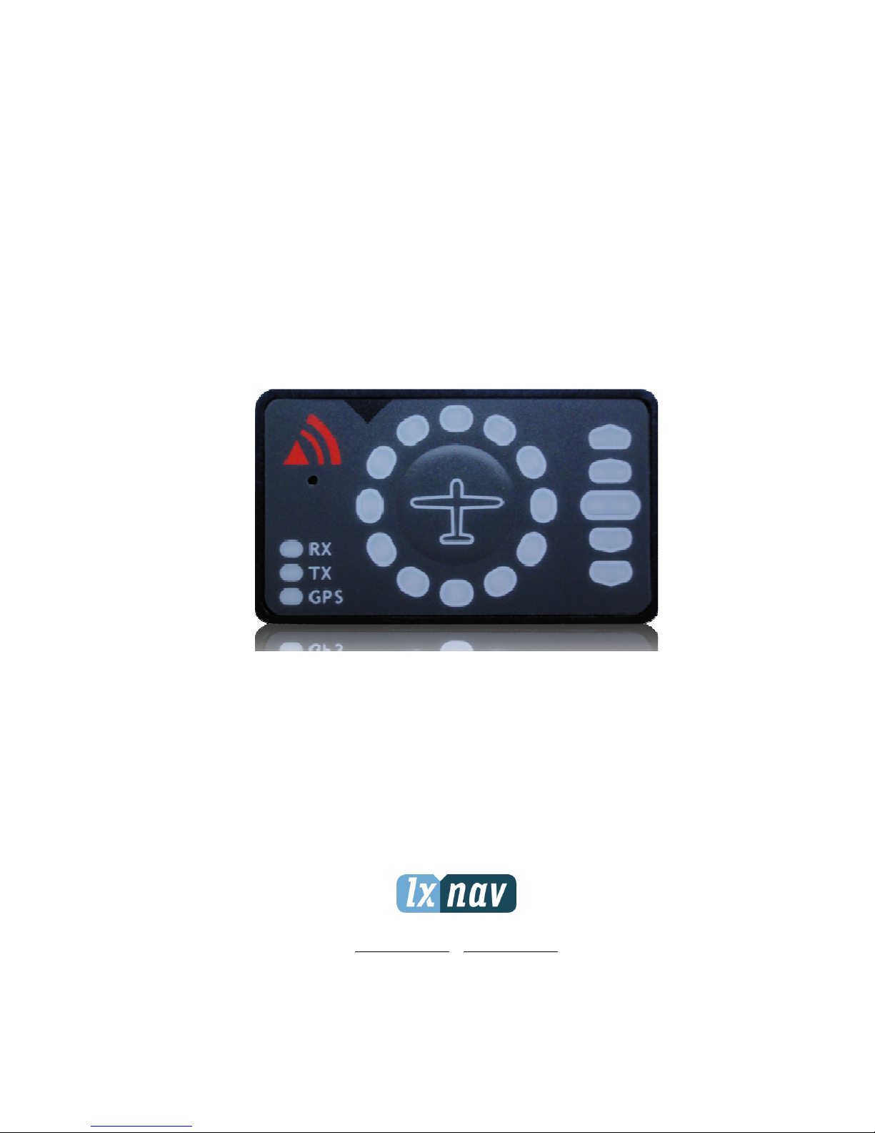
Flarm LED indicator
Version 1.1
LXNAV d.o.o. • Kidričeva 24a, 3000 Celje, Slovenia • tel +386 592 33 400 fax +386 599 33 522
info@lxnav.com • www.lxnav.com
Page 2

FlarmLed display Version 1.0 October 2013
Page 2 of 15
1 Important Notices 3
1.1 Limited Warranty 3
2 Packing Lists 4
3 Basics 5
3.1 LXNAV FlarmLed display at a Glance 5
3.1.1 LXNAV FlarmLed display features 5
3.1.2 Interfaces 5
3.1.3 Technical Data 5
4 System Description 6
4.1 Description of Flarm Led Display 6
4.1.1 Status LEDs 6
4.1.2 Horizontal direction LEDs 6
4.1.3 Vertical direction LEDs 6
4.1.4 Push Button 6
4.2 Normal operation 7
4.2.1 WARNING Modus: 7
4.2.2 NEAREST Modus: 7
4.2.3 Obstacle warning 7
4.2.4 Undirected PCAS warning 7
4.3 Powering up FlarmLed display 8
4.4 Setting up FlarmLed display 8
4.5 Other indications 8
4.5.1 Copying the IGC-file onto SD-card: 8
4.5.2 Running Flarm firmware update from SD-card 8
4.5.3 Copying the obstacle database from SD-card 9
4.5.4 Error codes from flarm 9
4.6 Wiring 13
4.6.1 FlarmLed pinout 13
4.6.2 FlarmMouse - FlarmLED 13
4.7 Cutout 14
5 Revision History 15
Page 3

FlarmLed display Version 1.0 October 2013
Page 3 of 15
1 Important Notices
The LXNAV FlarmLed display is designed for VFR use only as an aid to prudent navigation.
All information is presented for reference only.
Information in this document is subject to change without notice. LXNAV reserves the right
to change or improve their products and to make changes in the content of this material
without obligation to notify any person or organization of such changes or improvements.
A Yellow triangle is shown for parts of the manual which should be read carefully
and are important for operating the LXNAV FlarmLed display
Notes with a red triangle describe procedures that are critical and may result in
loss of data or any other critical situation.
A bulb icon is shown when a useful hint is provided to the reader.
1.1 Limited Warranty
This LXNAV FlarmLed display product is warranted to be free from defects in materials or
workmanship for two years from the date of purchase. Within this period, LXNAV will, at its
sole option, repair or replace any components that fail in normal use. Such repairs or
replacement will be made at no charge to the customer for parts and labour, the customer
shall be responsible for any transportation cost. This warranty does not cover failures due to
abuse, misuse, accident, or unauthorized alterations or repairs.
THE WARRANTIES AND REMEDIES CONTAINED HEREIN ARE EXCLUSIVE AND IN LIEU OF
ALL OTHER WARRANTIES EXPRESSED OR IMPLIED OR STATUTORY, INCLUDING ANY
LIABILITY ARISING UNDER ANY WARRANTY OF MERCHANTABILITY OR FITNESS FOR A
PARTICULAR PURPOSE, STATUTORY OR OTHERWISE. THIS WARRANTY GIVES YOU
SPECIFIC LEGAL RIGHTS, WHICH MAY VARY FROM STATE TO STATE.
IN NO EVENT SHALL LXNAV BE LIABLE FOR ANY INCIDENTAL, SPECIAL, INDIRECT OR
CONSEQUENTIAL DAMAGES, WHETHER RESULTING FROM THE USE, MISUSE, OR
INABILITY TO USE THIS PRODUCT OR FROM DEFECTS IN THE PRODUCT. Some states do
not allow the exclusion of incidental or consequential damages, so the above limitations may
not apply to you. LXNAV retains the exclusive right to repair or replace the unit or software,
or to offer a full refund of the purchase price, at its sole discretion. SUCH REMEDY SHALL
BE YOUR SOLE AND EXCLUSIVE REMEDY FOR ANY BREACH OF WARRANTY.
To obtain warranty service, contact your local LXNAV dealer or contact LXNAV directly.
May 2013 © 2013 LXNAV. All rights reserved.
Page 4

FlarmLed display Version 1.0 October 2013
Page 4 of 15
2 Packing Lists
• FlarmLed display
• cable
Page 5

FlarmLed display Version 1.0 October 2013
Page 5 of 15
3 Basics
3.1 LXNAV FlarmLed display at a Glance
FlarmLed display Flarm® compatible device, able to indicate horizontal and vertical direction
of a threat. Nearby traffic is displayed visually and acoustically. It’s extremely small size, low
power consumption, and has very bright bicolor LED’s.
3.1.1 LXNAV FlarmLed display features
• extremely bright bicolor LEDs
• pushbutton, to adjust beep volume
• near mode function
• adjustable baud rate
• slave mode
• Low current consumption
3.1.2 Interfaces
•
Serial RS232 input/output
•
pushbutton
•
12 bicolor LEDs for direction
•
5 LEDs for vertical angle
•
3 LEDs for GPS, Rx and Tx indication
3.1.3 Technical Data
• Power input 3.3V DC
• Consumption 10mA@12V (120mW)
• Weight 10 g
• 42mm x 25mm x 5mm
Page 6

FlarmLed display Version 1.0 October 2013
Page 6 of 15
4 System Description
4.1 Description of Flarm Led Display
Flarm led consist of 5 main parts:
• Status LEDs
• Horizontal direction LEDs
• Vertical direction LEDs
• Push button
• Beeper
4.1.1 Status LEDs
Status LEDs indicates if flarm receiver receives any data, transmits data and GPS status.
GPS status led has 3 different modes:
• Fast blinking mode, means, that FlarmLed does not receive anything over serial bus
(probably needs to set correct baud rate)
• Slow blinking means, that GPS status is BAD
• Solid light means, that GPS status is OK.
4.1.2 Horizontal direction LEDs
12 horizontal LEDs are indicating the direction of threat.
4.1.3 Vertical direction LEDs
5 LEDs are describing vertical angle of threat divided by 14°
4.1.4 Push Button
With push button we can adjust volume of beep, turning on/off near mode or adjust initial
settings of FlarmLed display.
Page 7

FlarmLed display Version 1.0 October 2013
Page 7 of 15
4.2 Normal operation
In normal operation with short press, we can cycle between three different volumes (Low,
Medium and High). With long press, is enabled or disabled near mode. Switching of mode is
also visually supported with moving light around circle. Red moving light means, that near
mode is enabled, yellow moving light means, that near mode is disabled.
4.2.1 WARNING Modus:
WARNING Mode will activate a red blinking diode, if another glider equipped with Flarm
will be close and a prediction for a collision risk is calculated. An audio warning will be also
executed. Higher collision risk will increase blinking frequency and audio beep rate. The
warnings are classified into three levels (See Flarm manual for details)
o First level approximately 18 seconds before predicted collision
o Second level approximately 13 seconds before predicted collision
o Third level approximately 8 seconds before predicted collision
4.2.2 NEAREST Modus:
Will show the direction to the nearest glider, which´s position is inside of radio range. One
yellow LED will light permanently and there will be no audio. The unit will change over to
Warning Mode automatically, if warning criteria will be fulfilled and will continue in
NEAREST after collision risk will disappear.
4.2.3 Obstacle warning
An obstacle warning will be activated, if an obstacle is to be found in the front of the glider
and a collision risk is predicted. The warning is shown with two red LEDs, symmetrical
around the 12 o´ clock LED at 10 and 2, they alternate with those at 11 and 1. As we
approach to the obstacle the frequency of the alternation increases.
4.2.4 Undirected PCAS warning
Is the FlarmLED connected to a device, which also translates transponder signals with ADS-B
data into Flarm warnings, you will receive them in the same logic as above. Transponder
signals without ADS-B data contain no direction for the thread therefore you will get an
undirected warning with the following alternating signals:
Page 8

FlarmLed display Version 1.0 October 2013
Page 8 of 15
4.3 Powering up FlarmLed display
LXNAV FlarmLed is powered directly from flarm device with 3.3Volts. When gets power it
passes boot up sequence with test of all LEDs and short beep, shows version of FlarmLed
display firmware (yellow led indicated major version, red indicates minor version).
4.4 Setting up FlarmLed display
If we hold push button, during power on, LXNAV FlarmLed will go in setup mode, where is
possible to adjust following settings:
• Communication speed
• Master/Slave mode
• Enable7disable PCAS warnings
Yellow led indicates mode that we are setting, Red LEDs indicates setting of each mode.
Red 12 Red 1 Red 2 Red 3 Red 4 Red 5
Yellow 12 Baud rate 4800bps 9600bps 19200bps 38400bps 57600bps 115200bps
Yellow 1 Master/Slave Master Slave / / / /
Yellow 2 PCAS Enabled Disabled
This setup is prepared because some FLARMs are set to different baud rates, so it’s
necessary also to set FlarmLed to same baud rate. Normally Flarm default baud rate is
19200bps, on that setting is also set FlarmLed display.
Master/Slave option is usable only if we have connected to flarm more than one Flarm led
display. In that case display can interfere each other. Only one can be set to Master, all
other must be set to slaves.
Last setting enables or disables PCAS warnings, which might be sometimes very annoying.
4.5 Other indications
The FlarmLED Display can indicated some further statuses:
4.5.1 Copying the IGC-file onto SD-card:
4.5.2 Running Flarm firmware update from SD-card
Page 9

FlarmLed display Version 1.0 October 2013
Page 9 of 15
4.5.3 Copying the obstacle database from SD-card
4.5.4 Error codes from flarm
Error
code
Description
Functionality
Display
0x11
Fault: Software
out of date
(needs GPS
reception)
No operation
0x12
Fault: Software
integrity violation
(only on IGCunits)
No operation
0x21
Fault: Low
Voltage
No operation
0x31
Fault:
Internal GPS
communication
No operation
0x32
Fault: Faulty GPS
configuration
No operation
Page 10

FlarmLed display Version 1.0 October 2013
Page 10 of 15
0x41
Fault: Internal
radio
communication
No operation
0x51
Fault: General
internal
communication
No operation
0x61
Fault: Flash
memory
No o
peration
0x71
Fault: Pressure
sensor
No operation
0xF1
Fault: Other fault
No operation
0x81
Indication: No
obstacle data
bank
Operation
possible
0x91
Indication: Flight
recording not
possible
Operation
possible
0x93
Indication:
Engine-noise
recording not
possible
(only on IGCunits)
Operation
possible
Page 11

FlarmLed display Version 1.0 October 2013
Page 11 of 15
0xA1
Indication: Error
with SD-card
configuration file
Operation
possible
0x2a
Indication:
Transponder
receiver mode
C/S/ADS-B
unserviceable.
Operation
possible
82 Indication:
Obstacle
database out of
date (alarms are
still
generated).
Operation
possible
B1 Indication:
Invalid
obstacle database
licence.
Operation
possible
B2 Indication:
Invalid
IGC feature
licence.
Operation
possible
B3 Indication:
Invalid
AUD feature
licence.
Operation
possible
B4 Indication:
Invalid
ENL feature
licence.
Operation
possible
B5 Indication:
Invalid
RFB feature
licence.
Operation
possible
Page 12

FlarmLed display Version 1.0 October 2013
Page 12 of 15
B6 I
ndication:
Invalid
TIS feature
licence.
Operation
possible
100 Indication:
Generic error.
Operation
possible
101 Indication:
Flash
File System error.
Operation
possible
110 Indication:
Failure
updating
firmware of
external display
(e.g.,Butterfly).
Operation
possible
120
Indication:
Device
is operated
outside
designated
region. Radio
performance may
be degraded.
Page 13

FlarmLed display Version 1.0 October 2013
Page 13 of 15
4.6 Wiring
4.6.1 FlarmLed pinout
Pin number Description
1 N.C.
2 (output) Transmit from LXNAV FLARM LED RS232 Level
3 (input) Receive to LXNAV FLARM LED RS232 Level
4 Ground
5 3.3V power supply (input)
6 N.C.
4.6.2 FlarmMouse - FlarmLED
Flarm Power
Supply Cable
FlarmLED
V7 Flarm
Splitter
FlarmMouse
Page 14

FlarmLed display Version 1.0 October 2013
Page 14 of 15
4.7 Cutout
Front view
Page 15

FlarmLed display Version 1.0 October 2013
Page 15 of 15
5 Revision History
May 2013
Initial release of owner manual
October 2013
Added chapters 4.2 and 4.
March 2014
Modified chapter 4.4
May 2014
Added error codes
 Loading...