

Page 1
FlarmACL
Installation manual
Version 1.15
LXNAV d.o.o. • Kidričeva 24, 3000 Celje, Slovenia • tel +386 592 33 400 • fax +386 599 33 52 2
info@lxnav.com
• www.lxnav.com
Page 2

FlarmACL Version 1.15 August 2018
Page 2 of 8
1 Important Notices 3
1.1 Limited Warranty 3
2 Packing list 4
3 Installation 5
3.1 Connection LXNAV FlarmACL 5
3.1.1 Wiring 5
3.1.2 Switch description 6
3.1.3 Unit operation 6
4 Automatic triggering of FlarmACL 7
5 Revision history 8
Page 3

FlarmACL Version 1.15 August 2018
Page 3 of 8
1 Important Noti ces
The LXNAV FlarmACL system is designed for VFR use only. All information is presented for
reference only. It is ultimately the pilot's responsibilit y to ensure the aircraft is being flown
in accordance with the manufacturer's aircraft flight manual. The FlarmACL must be
installed in accordance with applicable airworthiness standards according to the country of
registration of the aircraft.
Information in this document is subject to change without notice. LXNAV reserves the right
to change or improve their products and to make changes in the content of this material
without obligation to notify any person or organisation of such changes or improvements.
A Yellow triangle is shown for parts of the manual which should be read carefully
and are important for operating the LXNAV FlarmACL system.
Notes with a red triangle describe p rocedures that are critical and may result in
loss of data or any other critical situation.
A bulb icon is shown when a useful hint is provided to the reader.
1.1 Limited Warranty
This LXNAV FlarmACL product is warranted to be free from defects in materials or
workmanship for two years from the date of purchase. Within this period, LXNAV will, at its
sole option, repair or replace any components that fail in normal use. Such repairs or
replacement will be made at no charge to the customer fo r parts and labour, the customer
shall be responsible for any transportation cost. This warranty does not cover failures due to
abuse, misuse, accident, or unauthorised alterations or repairs.
THE WARRANTIES AND REMEDIES CONTAINED HEREIN ARE EXCLUSIVE AND IN LIEU OF
ALL OTHER WARRANTIES EXPRESSED OR IMPLIED OR STATUTORY, INCLUDING ANY
LIABILITY ARISING UNDER ANY WARRANTY OF MERCHANTABILITY OR FITNESS FOR A
PARTICULAR PURPOSE, STATUTORY OR OTHERWISE. THIS WARRANTY GIVES YOU
SPECIFIC LEGAL RIGHTS, WHICH MAY VARY FROM STATE TO STATE.
IN NO EVENT SHALL LXNAV BE LIABLE FOR ANY INCIDENTAL, SPECIAL, INDIRECT OR
CONSEQUENTIAL DAMAGES, WHETHER RESULTING FROM THE USE, MISUSE, OR
INABILITY TO USE THIS PRODUCT OR FROM DEFECTS IN THE PRO DUCT. Some states do
not allow the exclusion of incidental or consequential damages, so the above limitations may
not apply to you. LXNAV retains the exclusive right to repair or replace the unit or software,
or to offer a full refund of the purchase price, at its sole discretion. SUCH REMEDY SHALL
BE YOUR SOLE AND EXCLUSIVE REMEDY FOR ANY BREACH OF WARRANTY.
To obtain warranty service, contact your local LXNAV dealer or contact LXNAV directly.
March 2018 © 2018 LXNAV. All rights reserved.
Page 4

FlarmACL Version 1.15 August 2018
Page 4 of 8
2 Packing list
• LXNAV FlarmACL
• FlarmACL wiring harness
Page 5

FlarmACL Version 1.15 August 2018
Page 5 of 8
3 Installation
3.1 Connection LXNAV FlarmACL
3.1.1 Wiring
Page 6

FlarmACL Version 1.15 August 2018
Page 6 of 8
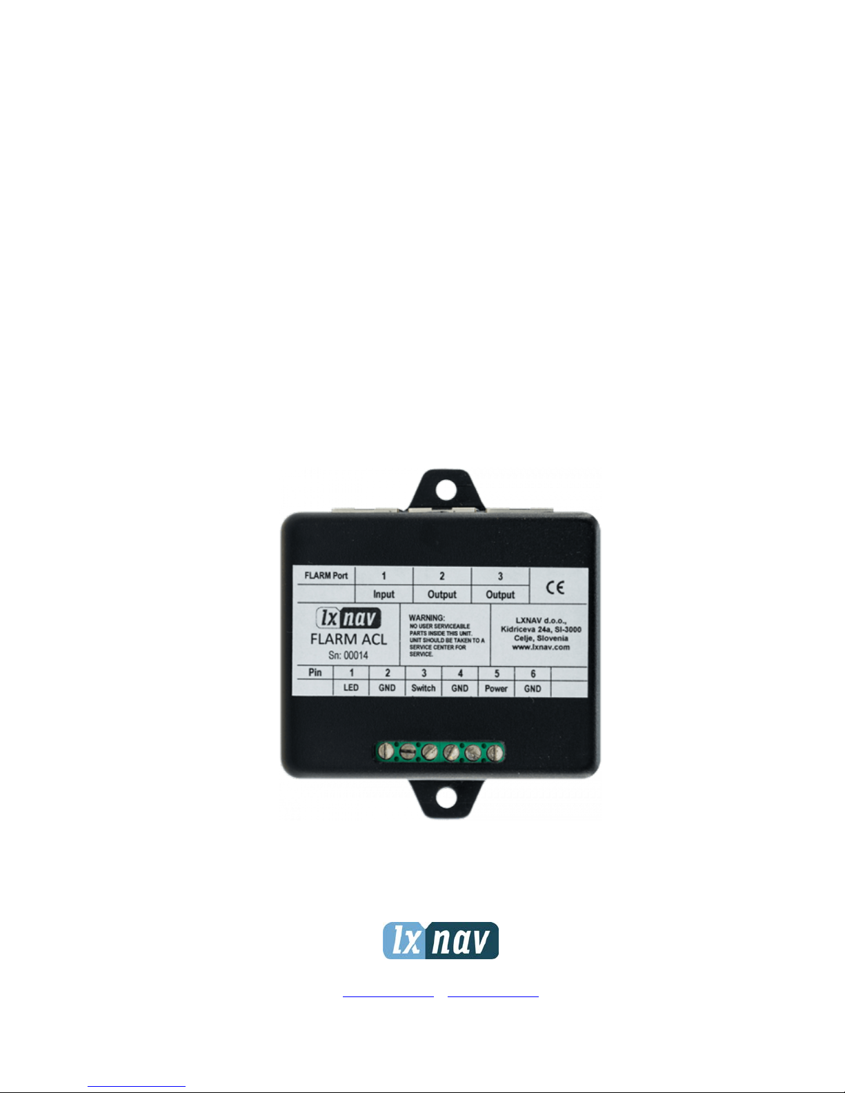
FlarmACL connects together Pin 1 from Port 1-3, Pin 2 from Port 1-3, etc. Pin names are:
1- +12V
2- +12V
3- +3,3V (Flarm displays)
4- GND
5- Data Input (Output)
6- Data Output (Input)
7- GND
8- GND
3.1.2 Switch description
3.1.3 Unit operation
The FlarmACL is powered via an external power connection (Screw terminal pin labelled
Power). Its own current draw is appr. 30 mA. The device list ens to any Flarm traffic (fixed
baudrate of 19200 – newer versions hav e an automatic baudrate detection) on any of the
three RJ45 connectors and switches on the connected strob e light via an internal solid-state
switch (Screw terminal pin labelled LED).
RJ45 connectors also act as a Flarm splitter device.
Control is done via the three-position switch with an integrated LED indicator:
• Top position: Output is switched ON, LED indicator is always ON and green
• Middle position: Output is switched OFF and disabled, LED indicator always
OFF
• Bottom position: Output is switched ON, the LED indicator is ON only when an
urgent alarm is detected, and red when this happens. If no alarm is issued
for 3 seconds the output is switched OFF.
Page 7

FlarmACL Version 1.15 August 2018
Page 7 of 8
4 Automatic triggering of FlarmACL
The FlarmACL will be automatically triggered under 2 conditions.
Condition 1:
• If the swi tch is set to AUTO and if any kind of flarm alarm is active
Condition 2:
• If the swi tch is set to AUTO and a plane is closer than 1000m.
Page 8

FlarmACL Version 1.15 August 2018
Page 8 of 8
5 Revision history
March 2018
Complete revision of this manual
August 2018
English corrected by JR
 Loading...