

Page 1
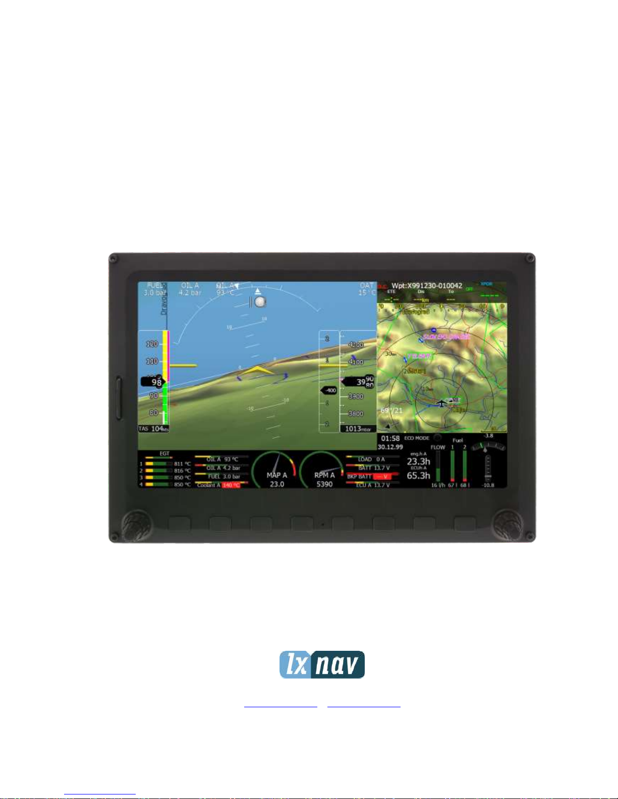
eCopilot
System Installation Manual 1.02
LXNAV d.o.o. • Kidričeva 24a, 3000 Celje, Slovenia • tel +386 592 33 400 fax +386 599 33 522
info@lxnav.com • www.lxnav.com
Page 2

1 Important Notices 4
1.1 Limited Warranty 4
2 Introduction 5
3 What is included in package 6
4 System Planning 7
4.1 Power Consumption 7
4.2 Power Supply 7
4.3 Dimensions and Weights 7
4.4 Temperature Specifications 8
4.5 Location Requirements 8
4.5.1 eCopilot10 8
4.5.2 eCopilot7 8
4.5.3 sBox (Sensor box) 8
4.5.4 eBox (Engine box) 8
4.6 Grounding and power supply requirements 8
4.7 Cooling Requirements 8
4.8 Mounting Requirements 8
5 Overview of the System 9
5.1 Overview 9
5.2 Communication BUS 9
5.3 Harness and Cables 9
5.4 Available Cables and Harnesses 9
5.5 Examples of Systems 10
6 Installation and Configuration 11
6.1 Main Unit and Repeater Unit 11
6.1.1 Installation of Options 11
6.1.2 Cut-Outs 11
6.1.2.1 eCopilot10 11
6.1.2.2 eCopilot7 12
6.1.3 Dimensions 13
6.1.3.1 eCopilot10 13
6.1.3.2 eCopilot7 13
6.1.4 Ports 14
6.1.4.1 eCopilot10 14
6.1.4.2 eCopilot7 15
6.1.4.3 Main Power supply 16
6.1.4.4 Flarm Port 16
6.1.4.5 CAN BUS ports 17
6.1.4.6 USB Port 17
6.1.1 Wiring 17
6.2 Connection and Functionality Check of All Peripheral Units 17
6.2.1.1 Wiring 18
6.2.1.2 Connection to the CAN Bus 18
6.2.1.3 Pneumatics 18
6.2.1.4 Audio 18
6.2.2 Installation of Options 19
6.2.2.1 Remote Sticks 19
6.2.2.2 ADSB Receiver 19
6.2.2.3 Flap Sensor 19
6.2.2.4 Wi-Fi Module 20
6.2.2.5 Compass Module 21
7 Troubleshooting 22
Page 3

7.1 Export Diagnostic Files 22
8 Revision History 23
Page 4
Important Notices Version 1.02, January 2019
Page 4 of 25
1 Important Notices
The LXNAV system is designed for VFR use only as an aid to prudent navigation. All
information is presented for reference only. Terrain, airports and airspace data are provided
only as an aid to situation awareness.
Information in this document is subject to change without notice. LXNAV reserves the right
to change or improve their products and to make changes in the content of this material
without obligation to notify any person or organisation of such changes or improvements.
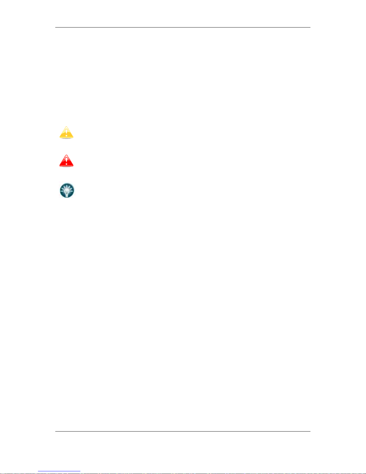
A Yellow triangle is shown for parts of the manual which should be read very
carefully and are important for operating the system.
Notes with a red triangle describe procedures which are critical and may result in
loss of data or any other critical situation.
A bulb icon is shown when a useful hint is provided to the reader.
1.1 Limited Warranty
This LXNAV product is warranted to be free from defects in materials or workmanship for
two years from the date of purchase. Within this period, LXNAV will, at its sole discretion,
repair or replace any components that fail in normal use. Such repairs or replacement will
be made at no charge to the customer for parts and labour, provided that the customer shall
be responsible for any transportation cost. This warranty does not cover failures due to
abuse, misuse, accident, or unauthorised alterations or repairs.
THE WARRANTIES AND REMEDIES CONTAINED HEREIN ARE EXCLUSIVE AND IN LIEU OF
ALL OTHER WARRANTIES EXPRESSED OR IMPLIED OR STATUTORY, INCLUDING ANY
LIABILITY ARISING UNDER ANY WARRANTY OF MERCHANTABILITY OR FITNESS FOR A
PARTICULAR PURPOSE, STATUTORY OR OTHERWISE. THIS WARRANTY GIVES YOU
SPECIFIC LEGAL RIGHTS, WHICH MAY VARY FROM STATE TO STATE.
IN NO EVENT SHALL LXNAV BE LIABLE FOR ANY INCIDENTAL, SPECIAL, INDIRECT OR
CONSEQUENTIAL DAMAGES, WHETHER RESULTING FROM THE USE, MISUSE, OR
INABILITY TO USE THIS PRODUCT OR FROM DEFECTS IN THE PRODUCT. Some states do
not allow the exclusion of incidental or consequential damages, so the above limitations may
not apply to you. LXNAV retains the exclusive right to repair or replace the unit or software,
or to offer a full refund of the purchase price, at its sole discretion. SUCH REMEDY SHALL
BE YOUR SOLE AND EXCLUSIVE REMEDY FOR ANY BREACH OF WARRANTY.
To obtain warranty service, contact your local LXNAV dealer or contact LXNAV directly.
May 2016 © 2016 LXNAV. All rights reserved.
Page 5

Introduction Version 1.02, January 2019
Page 5 of 25
2 Introduction
The printed version of this installation manual is in grayscale. Some figures and diagrams
are coloured. Please refer to electronic version to see colours. The latest electronic version
of this manual can be downloaded from http://www.lxnav.com section downloads-manuals.
This manual will guide you through the installation process of all systems, components,
basic setup and check of the system.
Before using any part of the system, please read and understand the installation
and user manuals!
There are no serviceable parts within the unit, hence the unit must be taken to
the factory for service.
Opening the unit by the user will void warranty and airworthiness.
Page 6
What is included in package Version 1.02, January 2019
Page 6 of 25
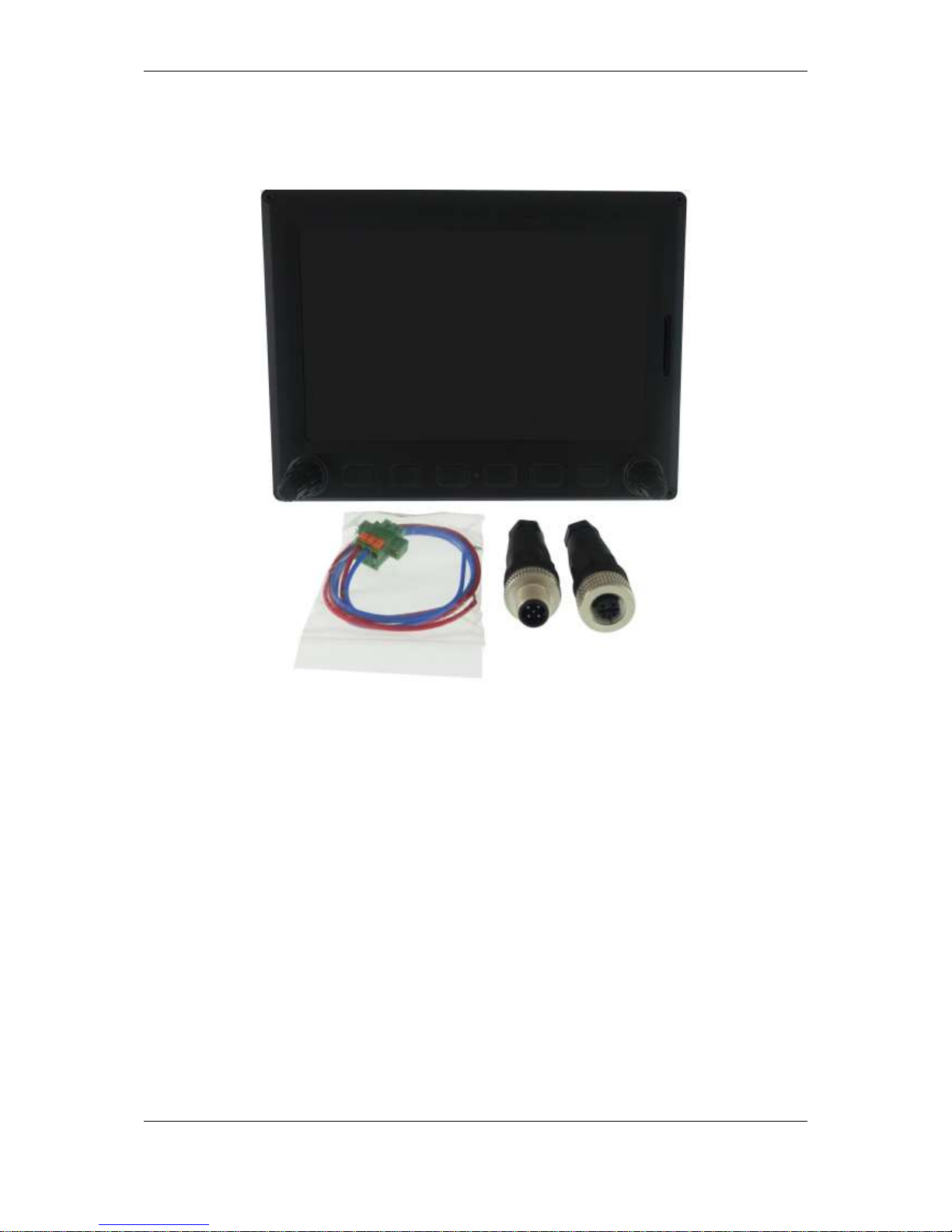
3 What is included in package
Page 7

System Planning Version 1.02, January 2019
Page 7 of 25
4 System Planning
In this chapter the installer will be informed how and where particular equipment items can
be installed. Some items have environmental and location requirements, others not.
4.1 Power Consumption
Some modules obtain power from the main unit. These modules do not need a circuit
breaker as the main unit takes care of this. Other items of equipment that have their own
power supply should have specified circuit breakers installed.
Approximate Current
Consumption at 12V DC
Recommended Circuit
Breaker
eCopilot10
800mA (at max. brightness)
3A
eCopilot7
800mA (at max. brightness)
3A
eBox
30mA
-
sBox -
4.2 Power Supply
Min. Voltage
Nominal Voltage
Max. Voltage
eCopilot10
9V
12V
28V
eCopilot7
9V
12V
28V
eBox
9V
12V
26V (optional to 36V)
sBox
9V
12V
28V
4.3 Dimensions and Weights
Dimensions
Weight
eCopilot10
256 x 176 x 55,5 mm
917 g
eCopilot7
182 x 136 x 56 mm
615 g
eBox
131 x 76 x 22 mm
232 g
sBox
105 x 57 x 34 mm
302 g
Page 8

System Planning Version 1.02, January 2019
Page 8 of 25
4.4 Temperature Specifications
Storage Temperature
Operating Temperature
eCopilot10
-40°C to +80°C
-30°C to +60°C
eCopilot7
-40°C to +80°C
-30°C to +60°C
eBox
-40°C to +80°C
-30°C to +60°C
sBox
-40°C to +80°C
-30°C to +60°C
4.5 Location Requirements
4.5.1 eCopilot10
- Requires 56 mm of space behind the panel.
- There is no need for additional space for harness.
- Choose a position so that the display will be viewable.
4.5.2 eCopilot7
- Requires 56 mm of space behind the panel.
- There is no need for additional space for harness.
- Choose a position so that the display will be viewable.
4.5.3 sBox (Sensor box)
- The sBox harness needs additional XX mm space
- Some space should be taken in account also for the pito-static tubes connection
- Choose a position near CG of plane
4.5.4 eBox (Engine box)
- It’s recommended to be installed behind firewall (cockpit side)
- The eBox harness needs additional XX mm space
- Choose a position near CG of plane
4.6 Grounding and power supply requirements
High current consumers (radio, transponders,…) must be separated from eCopilot system
with separate power line.
Never use airframe as a source of the ground. Air frame must be grounded only on one
place, where is connected to the battery. Currents through airframe are not recommended.
4.7 Cooling Requirements
Currently there are no cooling requirements. If possible, ventilation should pass through the
instrument panel to exchange some warm air. That will drop the temperature behind the
panel a few degrees.
4.8 Mounting Requirements
Most LXNAV units are fastened with screws.
Page 9

Overview of the System Version 1.02, January 2019
Page 9 of 25
5 Overview of the System
5.1 Overview
The LXNAV system consists of many different displays, units and sensors which talk to each
other via the CAN bus.
5.2 Communication BUS
Most devices in LXNAV system talk to each other via the CAN bus. We use standard
M12mm NMEA connectors. Bus must be terminated at the beginning and end of chain with
CAN terminators.
Another way of communication with peripheral devices is via the RS232 serial interface.
This interface is mostly used to connect 3rd party devices into the LXNAV system (external
Flarm, ADSB,…). For each device we have a specially designed cable. The RS232
connection should be done by RJ12connector on the back side of eCopilot unit.
5.3 Harness and Cables
The main unit cable has two power supply wires (red for positive +12V DC and blue for
ground potential. Third wire can be optionally connected to auxiliary power supply.
5.4 Available Cables and Harnesses
Cable Part Number
Description
CAN BUS cable 0.5m
CAN BUS cable 1m
CAN BUS cable 2m
CAN BUS cable 3m
CAN BUS terminator (male)
CAN BUS terminator (female male)
Page 10

Overview of the System Version 1.02, January 2019
Page 10 of 25
5.5 Examples of Systems
Basic Installation
Installation with S10x vario
More complex installation
General Connection Options
M12 CAN Female
M12 CAN Male
Main Power
Terminator
Terminator
Terminator
Terminator
eCopilot
eBox
sBox
eCopilot
sBox
Main Power
Terminator
Terminator
eCopilot
S10x
S10x-eCP
Radio/XPDR
bridge
Propeller
flap
AP
Servo 1
AP
Servo 2…
Page 11

Installation and Configuration Version 1.02, January 2019
Page 11 of 25
6 Installation and Configuration
6.1 Main Unit and Repeater Unit
Before cutting out the panel the whole cutting plan of the panel, including all indicators,
must be prepared. The next figure shows the cut-outs for all types of units that can be
installed into the panel.
Prepare the cut-out in the instrument panel according to the drilling template or DWG
document. Position the unit in the cut-out in the instrument panel. Tighten the unit with
attached 2.5 mm screws.
6.1.1 Installation of Options
6.1.2 Cut-Outs
6.1.2.1 eCopilot10
Drawing is not to scale
Page 12

Installation and Configuration Version 1.02, January 2019
Page 12 of 25
6.1.2.2 eCopilot7
Drawing is not to scale
Page 13

Installation and Configuration Version 1.02, January 2019
Page 13 of 25
6.1.3 Dimensions
6.1.3.1 eCopilot10
6.1.3.2 eCopilot7
Page 14

Installation and Configuration Version 1.02, January 2019
Page 14 of 25
6.1.4 Ports
6.1.4.1 eCopilot10
Main power supply
Flarm Port
CAN BUS ports
USB port
Page 15

Installation and Configuration Version 1.02, January 2019
Page 15 of 25
6.1.4.2 eCopilot7
USB port
CAN BUS ports
Flarm Port
Main power suppply
Page 16

Installation and Configuration Version 1.02, January 2019
Page 16 of 25
6.1.4.3 Main Power supply
Main power GND Auxiliary power
6.1.4.4 Flarm Port
1 2 3 4 5 6
Pin numbers
Pin Number
Description
1
(output) 12V DC, to supply GPS
2
(output) 3.3V DC (max 100mA)
3
GND
4
Data In
5
Data Out
6
Ground
On flarm port can be directly connected Flarm mouse or NANOx via NanoPower and CC-NP-LX cable.
Page 17

Installation and Configuration Version 1.02, January 2019
Page 17 of 25
6.1.4.5 CAN BUS ports
One CAN BUS port is male, another is female. Can bus must be terminated with CAN BUS
terminator on beginning and on end of CAN BUS line.
Figure 1: Pinout of M12 connectors a) male b) female
Table 1: M12 connector pinout
Pin Number
Type
Description
1
Shield
Cable shielding pin
2
PWR
Positive power supply
3
GND
Ground pin
4
CAN-H
CAN high signal line
5
CAN-L
CAN low signal line
6.1.4.6 USB Port
USB port can be used for data transfer via memory stick, to plug in WiFi Module and other
compatible devices.
6.1.1 Wiring
6.2 Connection and Functionality Check of All Peripheral Units
The main display unit is connected to 12 Volt power via the 3 pin connector. The main All
other units are connected via CAN bus.
Please ensure that all units are connected correctly before the first power on. The power
wires (red and blue) should be connected to the main display unit.
It is VERY IMPORTANT to use an external fuse (max. 3A). Power supply cables
should use a minimum of 0.5 mm² AWG20 wires.
Page 18

Installation and Configuration Version 1.02, January 2019
Page 18 of 25
6.2.1.1 Wiring
6.2.1.2 Connection to the CAN Bus
6.2.1.3 Pneumatics
6.2.1.4 Audio
Page 19

Installation and Configuration Version 1.02, January 2019
Page 19 of 25
6.2.2 Installation of Options
6.2.2.1 Remote Sticks
6.2.2.2 ADSB Receiver
6.2.2.2.1 TRX Tool
6.2.2.2.2 Connecting the TRX-1090 to the System
6.2.2.3 Flap Sensor
6.2.2.3.1 NMEA Bridge
The NMEA Bridge has been designed to expand a number of NMEA ports in the system. It
can be used as classic NMEA output for PDA device to feed a Mode-S transponder with
NMEA.
6.2.2.3.2 Radio Bridge (UPDATED)
The Radio Bridge is the same part of hardware as the NMEA Bridge. On the main unit it can
be configured as a Radio Bridge which can communicate with supported radios (for more
information please refer to the Radio/Transponder Bridge manual).
Page 20

Installation and Configuration Version 1.02, January 2019
Page 20 of 25
6.2.2.3.3 Transponder Bridge (UPDATED)
The Transponder Bridge is the same part of hardware as the NMEA Bridge. On the main
unit it can be configured as a Transponder Bridge which can communicate with the
supported Transponders (for more information please refer to the Radio/Transponder Bridge
manual).
6.2.2.3.4 CAN2CAN – Rotax 912IS
The CAN2CAN bridge is used whenever device with different CAN speed/protocol wants to
be connected to LX CAN BUS (eCopilot). Female SUB D9 connector on CAN2CAN adapter is
used for LX CAN and male SUB D9 for Rotax 912IS engine. Pinout is same on both sides,
but power is required only on LX side via appropriate CAN2CAN M12 cable.
Connector pinout for
LX CAN BUS SUBD9
Pin
Description
1 - 2
CAN-L
3
GND 4 -
5 - 6
-
7
CAN-H 8 - 9 PWR
6.2.2.4 Wi-Fi Module
The Wi-Fi dongle must be plugged into a USB port. The Wi-Fi dongle will be operational
when the unit which will have enabled that option and the wireless network are available.
Connector pinout for
Rotax 912IS CAN BUS
Pin
Description
1
-
2
CAN-L
3
GND 4 - 5 -
6
-
7
CAN-H 8 - 9 -
Page 21

Installation and Configuration Version 1.02, January 2019
Page 21 of 25
6.2.2.5 Compass Module
The compass module must be connected to the RS485 bus. It must be installed at a
location where there are no strong magnetic fields (iron or ferromagnetic materials) or
cables with AC current or fluctuating DC currents.
When installing the magnetic compass use screws made of non-ferromagnetic
materials (plastic or brass).
Orientation of the compass module marked on the housing as shown on picture above.
Page 22

Troubleshooting Version 1.02, January 2019
Page 22 of 25
7 Troubleshooting
7.1 Export Diagnostic Files
A Diagnostic file can be downloaded from the main unit under Setup-About. If a SD card
is in the SD socket the user can copy the diagnostic file to the SD card. If a Wi-Fi module is
plugged in and wireless network is available the user can send this file over EMAIL directly
to LXNAV.
Page 23

Revision History Version 1.02, January 2019
Page 23 of 25
8 Revision History
May 2016
Initial release of installation manual
November 2018
Modified chapter 6.1.4.5
Added chapter 6.2.2.3.4
January 2019
Modified chapter 6.1.4.4
Page 24

Page 25

LXNAV d.o.o. • Kidričeva 24a, 3000 Celje, Slovenia • tel +386 592 33 400 fax +386 599 33 522
info@lxnav.com • www.lxnav.com
 Loading...