

LXI LX7007 User Manual

LX7007 pro IGC
V1.0
Variometer and GPS-Navigation System
Draft

LX 7007 pro IGC V1.0 Apr.2005
Contents
1 GENERAL...........................................................................................................................................................................4
1.1 TECHNICAL DATA ...........................................................................................................................................................4
1.2 ROTARY SWITCHES AND KEYS (BUTTONS) ......................................................................................................................5
1.2.1 ON/START button - Switching the Instrument ON and OFF ..............................................................................5
1.2.2 MODE selector (rotary switch).............................................................................................................................6
1.2.3 UP/DOWN selector (rotary switch)......................................................................................................................6
1.2.4 ENTER button.......................................................................................................................................................6
1.2.5 ESC/OFF button ...................................................................................................................................................6
1.2.6 EVENT button.......................................................................................................................................................6
1.2.7 MC and BAL buttons.............................................................................................................................................6
1.2.8 ZOOM (rotary switch) ..........................................................................................................................................6
2 OPERATING MODES...........................................................................................................................................................7
2.1 SETUP ..........................................................................................................................................................................7
2.1.1 SETUP of Options not Requiring the Password ...................................................................................................7
2.1.1.1 QNH RES (QNH and Safety Altitude)................................................................................................................................ 8
2.1.1.2 LOGGER (FLIGHT RECORDER)..................................................................................................................................... 8
2.1.1.3 INIT................................................................................................................................................................................... 11
2.1.1.4 DISPLAY.......................................................................................................................................................................... 12
2.1.1.5 TRANSFER ...................................................................................................................................................................... 12
2.1.1.6 PASSWORD..................................................................................................................................................................... 12
2.1.2 SETUP of Options Requiring Access by Password,...........................................................................................13
2.1.2.1 AS SELECT (selection of airspace section)...................................................................................................................... 13
2.1.2.2 TP (Turn point)................................................................................................................................................................ 13
2.1.2.3 OBS. ZONE (Observation Zone) ...................................................................................................................................... 14
2.1.2.4 WARNINGS - Airspace Penetration and Height Warnings ........................................................................................... 19
2.1.2.5 SETUP GPS ...................................................................................................................................................................... 20
2.1.2.6 UNITS............................................................................................................................................................................... 20
2.1.2.7 GRAPHIC ......................................................................................................................................................................... 21
2.1.2.8 EDIT PILOTS (Pilot list) ................................................................................................................................................. 23
2.1.2.9 SETUP NMEA.................................................................................................................................................................. 25
2.1.2.10 SETUP PC......................................................................................................................................................................... 25
2.1.2.11 DEL TP/TSK..................................................................................................................................................................... 25
2.1.2.12 GLIDER POLAR.............................................................................................................................................................. 25
2.1.2.13 LOAD................................................................................................................................................................................ 26
2.1.2.14 SETUP TE COMP. ........................................................................................................................................................... 26
2.1.2.15 SETUP INPUT.................................................................................................................................................................. 27
2.1.2.16 SETUP LCD INDICATOR (LCD – Vario Indicator) ...................................................................................................... 27
2.1.2.17 COMPASS........................................................................................................................................................................ 29
2.1.2.18 ENL (Engine Noise Level)............................................................................................................................................... 29
2.1.2.19 PAGE 1 (Main Navigation Page) ...................................................................................................................................... 29
2.1.2.20 PAGE 3 (Additional Navigation Page)............................................................................................................................. 30
2.1.2.21 SETUP AUDIO................................................................................................................................................................. 30
2.1.2.22 SETUP ALARMS............................................................................................................................................................. 30
2.2 NAVIGATION FUNCTIONS .............................................................................................................................................30
2.2.1 GPS Page............................................................................................................................................................30
2.2.2 NEAR AIRPORT .................................................................................................................................................31
2.2.3 APT Airports, TP Turn Points and TSK Tasks....................................................................................................31
2.2.3.1 Navigation in APT, TP or TSK ......................................................................................................................................... 32
2.2.3.2 Airport Selection, Team and Wind Calculation................................................................................................................. 33
2.2.4 TP - Turn Points .................................................................................................................................................35
2.2.4.1 TP SELECT ...................................................................................................................................................................... 35
2.2.4.2 TP EDIT............................................................................................................................................................................ 36
2.2.4.3 TP NEW............................................................................................................................................................................ 36
2.2.4.4 TP delete ........................................................................................................................................................................... 36
2.2.4.5 TEAM ............................................................................................................................................................................... 36
2.2.4.6 WIND................................................................................................................................................................................ 36
2.2.4.7 TP QUICK - Storing of actual position ............................................................................................................................ 36
2.2.5 TSK - Task..........................................................................................................................................................37
2.2.5.1 TSK - SELECT ................................................................................................................................................................ 38
2.2.5.2 TSK - EDIT..................................................................................................................................................................... 38
2.2.5.3 TSK - NEW..................................................................................................................................................................... 40
2.2.5.4 TSK - DECLARE............................................................................................................................................................ 40
2.2.6 STATISTICS........................................................................................................................................................41
Page 2

LX 7007 pro IGC V1.0 Apr.2005
2.2.6.1 Statistics during flight ....................................................................................................................................................... 41
2.2.6.2 Statistics after flight........................................................................................................................................................... 42
2.3 VARIOMETER AND ALTIMETER.....................................................................................................................................43
2.3.1 Smart Vario description......................................................................................................................................44
2.3.2 Altimeter .............................................................................................................................................................44
2.3.2.1 IGC barogram recalibration procedure.............................................................................................................................. 44
2.3.3 Speed command ..................................................................................................................................................44
2.3.4 Final glide calculation........................................................................................................................................45
2.4 FLYING WITH THE LX 7007 PRO IGC..........................................................................................................................45
2.4.1 Switching ON and selecting pilot........................................................................................................................45
2.4.2 SET Elevation (take off elevation input) ............................................................................................................46
2.4.3 Preflight check....................................................................................................................................................47
2.4.4 Performing the flight...........................................................................................................................................47
2.4.4.1 Preparing a task................................................................................................................................................................. 47
2.4.4.2 Starting a task.................................................................................................................................................................... 48
2.4.4.3 Automatic swap on reaching a TP using standard task and AAT ...................................................................................... 49
2.4.4.4 Use of MOVE function ..................................................................................................................................................... 49
2.4.4.5 TSK END.......................................................................................................................................................................... 50
2.4.4.6 Procedure after landing ..................................................................................................................................................... 50
2.4.4.7 SIMPLE TASK ................................................................................................................................................................. 51
3 PC, PDA AND COLIBRI/LX20 COMMUNICATION ..........................................................................................................51
3.1 COMMUNICATION WITH PC..........................................................................................................................................52
3.1.1 Some help having problems with communication...............................................................................................53
3.1.1.1 General.............................................................................................................................................................................. 53
3.1.1.2 Troubleshooting with LXE................................................................................................................................................ 54
3.1.1.3 Recommended LXE settings for safe communication....................................................................................................... 55
3.1.2 Having problems downloading flights (read selected flight-command)..............................................................56
3.1.3 Additional help from LX navigation....................................................................................................................56
3.2 COMMUNICATION WITH PDA.......................................................................................................................................57
3.2.1 Connect procedure to PDA.................................................................................................................................57
3.3 COMMUNICATION BETWEEN LX 7007, COLIBRI OR LX 20 ...........................................................................................58
3.3.1 Data transfer LX 7007-LX 20 .............................................................................................................................58
3.3.2 Data transfer LX 7007-Colibri ...........................................................................................................................58
4 INSTALLATION ................................................................................................................................................................59
4.1 INSTALLATION OF PDA UNITS......................................................................................................................................60
4.2 LX 7007 PRO IGC FULL CONFIGURATION (ALL CONNECTIONS PLUG AND PLAY) ...........................................................61
4.3 WIRING ........................................................................................................................................................................63
4.4 TREE STRUCTURE DIAGRAM .........................................................................................................................................65
5 PASSWORDS.....................................................................................................................................................................66
6 OPTIONS ..........................................................................................................................................................................67
6.1 LX 7007 PRO IGC - COMPASS MODULE .....................................................................................................................67
6.1.1 General ...............................................................................................................................................................67
6.1.2 Installation of the compass module.....................................................................................................................68
6.1.2.1 Where to install:................................................................................................................................................................ 68
6.1.2.2 First test after installation:................................................................................................................................................. 68
6.1.3 Adjusting the compass module:...........................................................................................................................68
6.1.4 Final test:............................................................................................................................................................68
6.1.5 Wind calculation during flight............................................................................................................................69
6.2 LX 7007 PRO IGC – REMOTE CONTROL UNITS............................................................................................................70
6.2.1 Remote control keyboard type.............................................................................................................................70
6.2.1.1 General.............................................................................................................................................................................. 70
6.2.1.2 Getting started................................................................................................................................................................... 70
6.2.1.3 Electronic connection........................................................................................................................................................ 71
6.2.2 LX 7007 PRO IGC – Remote K- Stick mounted unit...........................................................................................71
6.2.2.1 General.............................................................................................................................................................................. 71
6.2.2.2 LX 7007 PRO IGC Remote K configuration..................................................................................................................... 71
6.2.2.3 Stick handle with keys....................................................................................................................................................... 71
7 REVISION HISTORY .........................................................................................................................................................72
Page 3

LX 7007 pro IGC V1.0 Apr.2005
1 General
The instrument consists of two units, the LX 7007 DU main unit, and the LX 7007 AU LCD Vario indicator unit. The
80mm diameter (3") main unit LX 7007 DU is fitted with an integral 12 channel GPS receiver and a high resolution
display with 160x240 pixels. The 57 mm diameter (2 1/4") LX 7007 AU is a new design with its own integral micro
processor and communicates with the LX 7007 DU via the RS 485 system bus. Optionally, additional LX digital Vario
indicators can be daisy chained using the RS 485 bus.
Vario functions include:
• Vario, Netto, Relative (Super Netto) and Averager (new algorithms for vario signal acquisition added)
• Speed command
• Final glide calculator
• TE compensation is selectable for either pneumatic TE tube, or electronic TE
Navigation functions include:
• Airport and airspace database for Europe or USA (up to 5000 airports)
• 600 turn points
• 100 tasks
• Statistics
• Display of nearest airports
• Support of AAT (assigned area task)
What does LX 7007 PRO IGC mean?
The LX 7007 PRO IGC has an integral IGC approved flight recorder utilizing a dedicated pressure sensor for pressure
altitude recording based on 1013.2 hpA (29.92"). An integral engine noise capability is fitted for self sustaining and self
launching sailplanes. The firmware ensures data integrity and meets all IGC requirements regarding security of the
flight record data.
1.1 Technical data
• Power 8-16 V DC
• Consumption 400mA @ 12V (without audio)
• 80mm (3") standard Aircraft cut-out for LX 7007 DU
• 57mm (2 1/4") standard Aircraft cut-out for LX 7007 AU
• Length 120 mm (incl. connector)
• There physically separated com. Ports:
-PDA port with 5V power supply, delivers NMEA or allows data exchange LX 7007-PDA
- PC port
- IGC com port with IGC standard connector, suitable to connect Colibri or LX 20
-User com. port for some future applications
• Drives SeeYou mobile, Navigator, Winpilot….
• PDA communication with Connect LX
• 12 Channel GPS receiver
• memory space to store the whole European airspace
• External speaker
• Built in fuse to prevent damages in stead of a short on 485 bus
• Data compatible with LX 20 and Colibri
• IGC approved flight recorder
• Wiring
• Additional LCD Vario, rear seat unit, remote control and compass options can be connected via the RS 485 bus
• Weight: 800g
Page 4
LX 7007 pro IGC V1.0 Apr.2005
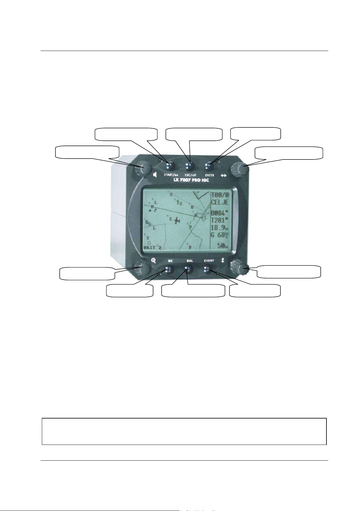
1.2 Rotary switches and keys (buttons)
The following controls are mounted on the front face of the LX7007 DU
• Four rotary selector switches
• Six push buttons
The LX7007AU is an indicator only and has no controls; the displayed information being controlled from the
LX7000DU
VOLUME selector
ZOOM selector
START/ON button ESC/OFF button
MC button BALLAST button EVENT button
ENTER button
MODE selector
UP/DOWN selector
1.2.1 ON/START button - Switching the Instrument ON and OFF
The ON/START button is multifunctional. If the instrument is not already powered up, a short press on the
ON/START button will switch the instrument ON. To switch the instrument OFF, press the ESC/OFF button for a
few seconds and the instrument will switch off. If an attempt is made to switch the instrument off during flight, the
instrument requires confirmation from the pilot, so the LX 7007 PRO IGC cannot be switched off by mistake. On
powering the unit, the first screen shows the firmware version, database version, serial number of the unit, and total
memory in hours available for IGC flight records. After a few seconds, a second screen shows details of the glider and
pilot. The unit is equipped with a facility of storing up to 30 pilot names. If no names are stored, the unit shows the
pilot name as UNKNOWN. By rotating the UP/DOWN selector, the display scrolls through the programmed pilots.
Once the correct pilot is selected, pressing the ENTER button selects the airfield elevation screen and the current
elevation should be entered, again using the UP/DOWN selector and the ENTER button. Similarly, the current QNH
should also be entered. The airfield elevation input is mandatory while the QNH input optional (See Para 3.1.1.1)
During flight the same button is used to start the task, to see more characters of airport names and, in the edit
menu, to go back one step if an error has been made (see paragraph APT).
Note!:
During flight, if main power is lost for a few seconds, the flight recorder will not produce two flights. The most
important flight parameter, altitude will remain, which means that the final glide is not interupted.
Page 5
LX 7007 pro IGC V1.0 Apr.2005
1.2.2 MODE selector (rotary switch)
The mode selector is used to change modes of operation. This switch has the highest priority in the system. Whenever
it is operated, a mode change will occur.
1.2.3 UP/DOWN selector (rotary switch)
This rotary switch has a lower priority than the mode selector switch and is active all the time in the selected mode. It is
mainly used for selecting sub menus during navigation and to scroll in the edit menu.
1.2.4 ENTER button
The main function of this key is confirmation, and to start edit procedures.
1.2.5 ESC/OFF button
This is a multifunctional key, which has two main functions. If it is pressed and held for a few seconds, then the
instrument will turn OFF as outlined in para 2.2.1 above.
If a short press is made, then the button has the following functions:
• The display will jump to the menu of the next higher level (in edit only)
• During alpha-numeric input with the cursor active (blinking), ESC confirms the whole line (It is not necessary to
press ENTER few times)
• Some special functions can be activated using ESC as described in subsequent paragraphs
1.2.6 EVENT button
Activates the Event function (see Chapter 3.1.1.2, Flight Recorder)
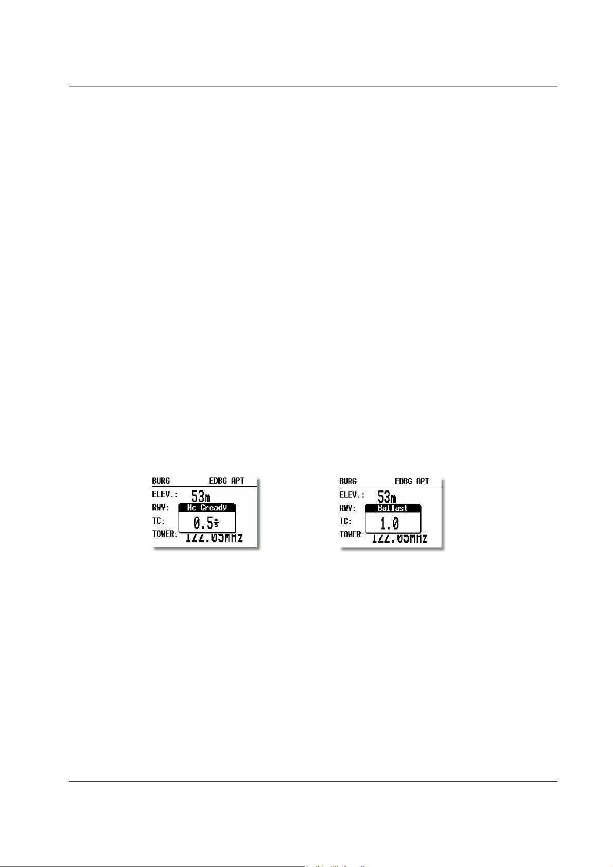
1.2.7 MC and BAL buttons
Pressing these buttons activates the Mc Cready (MC) and ballast setting as shown below. The value is then changed with
the UP/DOWN-selector. There is no secondary function of these buttons.
1.2.8 ZOOM (rotary switch)
This is a multifunctional rotary switch. While its main function is to change the zoom level in the graphic mode, it can
also be used as follows:
• To select turn points when in the main TP page
• To select task when in the main TSK page
• If an error is made during editing, it is possible to move the cursor back by rotating this knob. This can only be
done if 'editing' is active which is shown by the cursor blinking
Page 6
LX 7007 pro IGC V1.0 Apr.2005
⇐
2 Operating modes
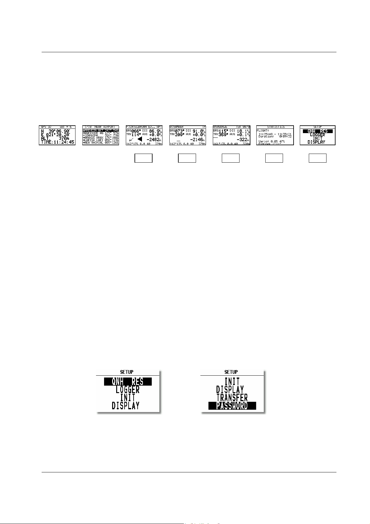
The LX 7007 PRO IGC has 7 modes or main menus. All of them are selectable directly by rotating the MODE switch.
The diagram shows the menu (mode) structure of LX 7007 PRO IGC.
MODE⇒
GPS NEAR APT TP TSK STAT SETUP
⇓ ⇓ ⇓ ⇓ ⇓
⇓ ⇓ ⇓ ⇓ ⇓
Navigation menus (APT, TP and TSK) have sub menus, which can be selected using the Up/Down switch.
GPS GPS status, no inputs possible
NEAR Near airport, select one airport of interest, no further inputs are possible
APT Navigation and selection of airports
TP Navigation, selection and editing of turn points
TSK Navigation, selection and editing of tasks
STAT Flight statistics and logbook
SETUP has two levels. The first level, for which no password is required, is fully accessible. To activate the second
level, it is necessary to input a password. The password is not top secret; it is the same for all instruments and is freely
available.
96990
The selection of the system parameters that are fixed, such as glider type, units, polar etc, are only access able by
entering the password. This facility prevents that well known gliding club pest, "the random knob twiddler" from
changing the important fixed parameters just before you launch on the flight of the year! Once you are airborne, then
the password is not necessary - the second level can be entered simply by selecting PASSWORD and pressing
ENTER.
2.1 SETUP
2.1.1 SETUP of Options not Requiring the Password
The first five options are selected with the UP/DOWN switch and can be entered at any time; they contain no system
settings.
Once the desired option has been selected, press ENTER to access the sub-menu.
Page 7
LX 7007 pro IGC V1.0 Apr.2005
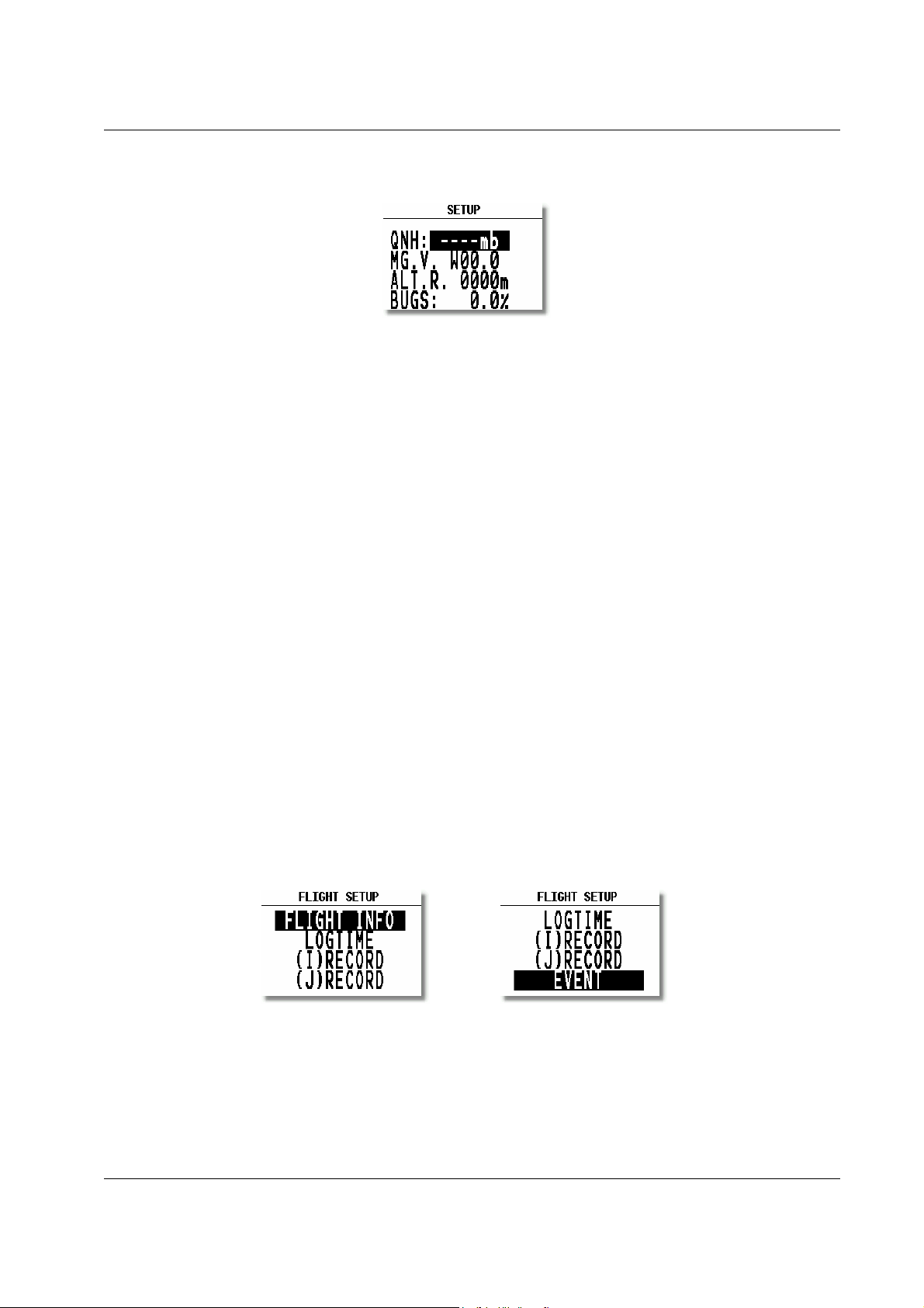
2.1.1.1 QNH RES (QNH and Safety Altitude)
Input Procedure:
• Use the UP/DOWN selector to choose the item it is required to change (QNH, MG.VAR, ALT.R. or BUGS)
• Press ENTER
• Use UP/DOWN to select the value required and press ENTER to input it
• Once all changes are complete, press ESC top return to SETUP menu
QNH: Using this feature it is possible to offset the altitude datum, which could have changed due to pressure changes
during the flight. During the initial power up sequence, an option to enter the QNH was presented. If the actual QNH
was entered at that stage, then this feature is active. If the QNH feature was 'stepped over' during power up, then this
function is not active. As changing the QNH influences the indicated altitude, care should be taken when changing the
value as an incorrect setting can upset the final glide calculation.
MG. V. If the GPS receiver calculates magnetic variation then AUTO will be displayed here and no input is possible.
If AUTO is not displayed, then the GPS receiver is not calculating magnetic variation and it is obligatory to input the
magnetic variation for the area being flown over. If this is not done, then all calculated winds and tracks flown will be
true and not magnetic.
ALT.R. This setting is the altitude reserve or safety altitude, and is the height that the instrument adds to the final glide
altitude required so that the glider arrives over the final glide destination at the selected safety altitude. After safety
altitude input, the pilot has has to keep final glide indicator on 0 to arrive on safety altitude.
BUGS: This sets the polar degradation because of “buggy” wings. The input is in percentage degradation of glide
ratio. (5%, means glide ratio degradation is 5%)
2.1.1.2 LOGGER (FLIGHT RECORDER)
The flight recorder is fully approved by the IGC (A sub-committee of the FAI.) and will produce secure flight records
that are acceptable for all FAI requirements including world records.
After selecting LOGGER and pressing ENTER, the following flight recorder settings are accessible.
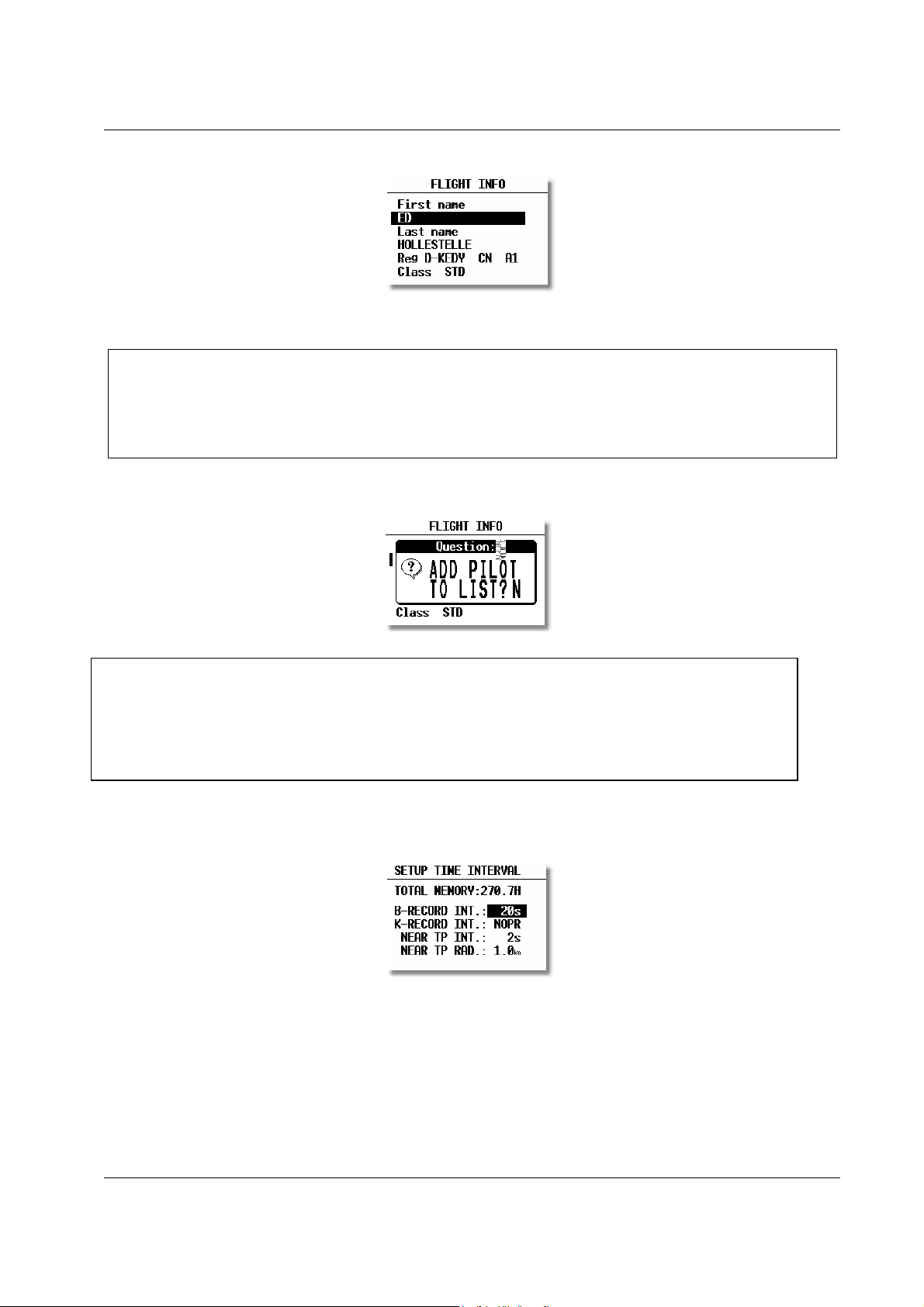
FLIGHT INFO All important data, such as the pilot's name, glider type, glider registration, competition number and
competition class can be entered. The data is entered with the ENTER, UP/DOWN and ESC routine. This data is
subsequently written into the 'H' record of the IGC flight log. Alternatively, this data can be entered with a PC and the
LXe-program; or via a Colibri or LX20 (see Chapter 4).
Page 8
LX 7007 pro IGC V1.0 Apr.2005
The instrument is cabable of storing up to 30 different pilot's names. Each pilot's name, which can be password
protected, can have different flight information programmed into it. This is useful if one likes to fly with a custom
polar, fly the glider in different configurations, or fly in decentralized competitions, Online-Contest, Barron-HiltonCup, etc. For more information on configuring pilot names see 3.4.1, and for for setting custom polars see 3.1.2.10.
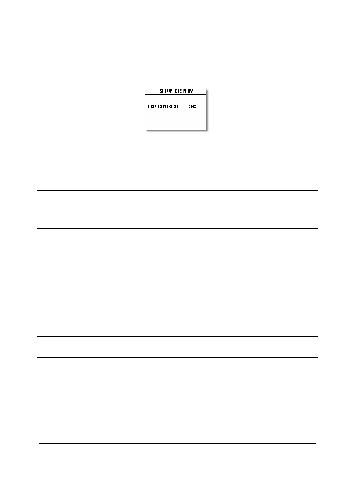
Before leaving the FLIGHT INFO menu, the actual name can be saved into pilot list, if not already present.
Note!:
If only one pilot flies the glider, then after entering his name, it is not necessary to enter it into the list. In the
above screen 'N' should be selected to do this. The name will then appear automatically on instrument power up
together with all the parameters that have been set. An exception to this is if he flies the glider in two different
configurations; then he should list his name twice, e.g once with a suffix of 15m and again with a suffix of 18m
with different polars in each name.
Note!:
LOGTIME is an important parameter as it shows the total memory available for recording the flight.
TOTAL MEMORY is the capacity of memory in hours that can be stored and only depends on the settings. It does
not decrease as flights are stored and will only change after new settings have been made in the setup. If the memory is
full, the oldest flights will be overwritten without warning. The total memory simply indicates how many hours of
flight can be made without loosing any flight data before overwriting occurs.
B-RECORD: This is the main IGC record in which position, GPS altitude, pressure altitude, UTC and GPS status are
stored. The default interval is 12 seconds and it can be changed. As the interval is reduced, the Total Memory will be
seen to decrease.
Page 9

LX 7007 pro IGC V1.0 Apr.2005
K-RECORD: This record can be used to store non-essential flight parameters and is not active by default. It should not
be activated unless the IGC record format is fully understood. If required to be activated, the J-Record (see below) will
select the flight parameters that are stored in the K-Record.
NEAR TP INT: This setting enables the fixing rate set by the B-Record to be increased close to a turnpoint to ensure
that a fix is obtained in the observation zone.
NEAR TP RAD: This setting defines the radius from the turnpoint at which increased fixing rate is to start.
(I) RECORD: This record permits additional flight parameters to be added to the B-Record. Except for ENL (Engine
Noise Level), they are all de-activated by default. They can be activated if required by toggling the 'N' to 'Y'.
-FXA: current horizontal accuracy of GPS
-VXA: current vertical accuracy of GPS
-RPM: engine RPM
-GSP: ground speed
-IAS: indicated airspeed
-TAS: TAS
-HDM: mg. heading
-TRM: magnetic track
-TRT: true track
-TEN: total energy
-WDI: wind direction
-WVE. wind
-VAR: vario
-ENL: engine noise level (default Y)
Each setting activated will reduce the total memory capacity.
(J) RECORD: The J-Record defines the flight parameters that are to be stored in the K-Record. These parameters are
the same as those used for the I-Record. Using this record will reduce the total memory by about half.
Unless the user has a good understanding of the composition and use of IGC flight records, then it is recommended
that, other than the ENL, no alterations are made to the default selections.
Note!:
EVENT This option programs what happens on pressing the EVENT button. On pressing the button, the flight
recorder places a special marker, called a PEV (Pilot Event), in the IGC flight record At the same time, it causes the
recorder to run at a different fix interval for a certain time. The interval and time are set up in this option.
Competition rules may require the EVENT to be activated at some stage during the flight.
Example:
The setting above will cause the recorder to log 30 additional fixes at 2-second intervals on pressing the EVENT button.
Page 10

LX 7007 pro IGC V1.0 Apr.2005
2.1.1.3 INIT
The following parameters can be set using this option.
• VARIO FIL: This sets the time constant of the vario from 0.5sec up to 5 secs; the default setting is 2.0 secs
• S.V. : S.V. means Smart Vario, giving four levels of dynamic damping of the vario indication and
off.
• VARIO INT: This setting defines integration period for the averager in seconds; the default is 20 seconds
• VARIO RNG: This sets the full scale range of the vario
• TAB: This setting defines the width of the audio dead band in speed to fly mode
• ETA: This setting selects the parameter, GS, VAR or MC, that is used to calculate the Estimated
Time of Arrival. When flying a programmed task, the calculation takes account of the
unflown portion of the task , around any TPs or APTs not yet reached
GS, bases ETA on the achieved groundspeed along track. It takes into account differences
between bearing and track of up to 90°. If the difference is greater than this, --:-- is
displayed.
VAR is based on the achieved average thermal climb rate and assumes that this is going to
continue.
MC is based on the actual Mcready setting.
Note!:
All three methods of calculating ETA and ETE (Estimate Time of Arrival, Estimate Time Elapsed) take into account
glider altitude and safety (arrival) altitude, thus ensuring that the calculation made is the best available
• AUTO SC: This option defines the method by which the instrument is switched between vario and speed
command
OFF: Switching is by an external switch
GPS: When the GPS detects that the glider is circling
TAS: When the TAS exceeds a pre-set value. The TAS at which switching occurs can be
selected in 5 km/h steps from 100 up to 160 km/h (or the equivalent in knots or mph)
• WIND/COMPASS: N.C. means not connected. When the optional compass module is installed, the instrument
uses magnetic track to make an additional wind calculation. The calculation requires the
glider to fly straight a specified period which is set in this option. The default is 15 seconds,
but the longer the period, the more accurate is the calculated wind.
Note!:
The external switch option has absolute priority and will override all other switching methods.
Page 11
LX 7007 pro IGC V1.0 Apr.2005
2.1.1.4 DISPLAY
This option sets the contrast of the LC display. The actual contrast can vary with viewing angle, ambient light level and
temperature. The contrast is changed by rotating the UP/DOWN selector.
Default contrast setting is 50%.
2.1.1.5 TRANSFER
This option initiates the transfer of data between the instrument and a connected PC, PDA, LX 20 or Colibri. Data
transfer is started by pressing ENTER with TRANSFER selected.
A dialog will open and the pilot has to select the destination.
PC
PDA
COLIBRI/LX 20
IGC PORT
Note!
After ENTER on PC the communication LX 7007 – PC via 5P connector usually mounted on the instrument panel will
be possible. After enter on IGC PORT a PC communication via IGC port and IGC standatd connector will be possible.
After PDA activation data exchange LX 7007 – PDA will be possible, suggested program is ConnectLX. Available on
www.lxnavigation.si or www.seeyou.ws.
Note!
PDA port is under normal conditions delivering NMEA data sentences to run PDA (SeeYou Mobile, Navigator
Winpilot…) and powers PDA at the same time.
After Enter on Colibri/LX 20, the data exchange with eventually connected Colibri or LX 20 device will be possible
(read/write TP&TSK, read and write of flight info).
Note!
As mentioned before, all three communications ports are physically separated and therefore no data collision problem
could occur, even all devices connected and on.
See Chapter 4 for further details.
2.1.1.6 PASSWORD
Certain system parameters can only be entered through this option. Full details are in the following paragraph, 3.1.2.
The Password is 96990
Page 12
LX 7007 pro IGC V1.0 Apr.2005
2.1.2 SETUP of Options Requiring Access by Password,
After entering the password, 96990, a further 21 system settings are available. During flight the password is not
required, which means that when ENTER is selected in the Password option during flight, the LX 7007 PRO IGC
goes immediately into the following setup menu!
2.1.2.1 AS SELECT (selection of airspace section)
The unit is able to store up to 6 sections (0 up to 5) of airspace, which means practically the whole European airspace.
The unit is delivered fully loaded. Selection of suitable area should be done by pilot using of this menu. After selection
simple press Enter and loading procedure will start automatically. To make airspace visible on PC screen use LXe or
LXAsbrowser PC program.
Note!
To reload a new airspace section (.CUB format only) is done simple by overwriting of actual active airspace using of
LXe PC program, exclusively.
Note!
To prepare custom airspace, in .CUB files, use our special tool for airspace creation and manipulation, called
LxAsbrowser, available for free on www.lxnavigation.si or on LXe CD.
EU-N…….. N,S, GB*, FIN*
EU- W………SP,P, F*, GB*, IRL*
EU-CS………CH, A, SLO, F*, D*, CZ*, HR*, I*
EU-CW……..BENELUX, CH, DK, D*, F*
EU-NE………N, S, DK, FIN*
EU-S………...CH, I, SLO, F+, HR*, A*
EU-C……….D, NL, CH, DK, A*, CZ*, B*
EU-E……….CZ, SK, PL, H, SLO, D*, HR*, RO*
EU-NW…….GB, IRL, BENELUX, Iceland, F*
EU-SW……..P, SP, F
* Not fully covered county.
Note!
Selection of believable airspace section is possible during the flight too and will take apr. one second.
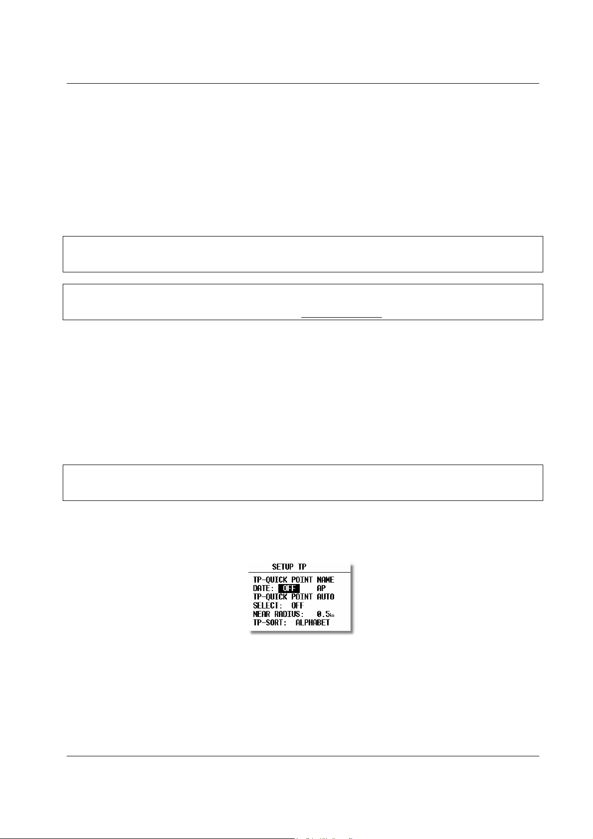
2.1.2.2 TP (Turn point)
All settings concerning turn points can be done in this menu. The LX 7007 PRO IGC is able to store 600 turn points in
a proprietary format (*.DA4).
TP-QUICK POINT NAME
The pilot is able to store his actual position during the flight by pressing the START button in TP mode in the first
navigation page (see Para 3.2.4.7). These turn points are called QUICK TP and are given the default name AP (actual
point).
Settings:
DATE: OFF stores the position as AP: 12:35. The numbers are the time that the TP was stored.
DATE: ON stores the position with the date and time (28121330 for 28 Dec. 13:30).
Page 13

LX 7007 pro IGC V1.0 Apr.2005
TP-QUICK POINT – AUTO
When SELECT: OFF is selected, the actual position will not be selected for navigation
When SELECT: ON is selected, the actual position will be selected automatically and displayed in the navigation page.
NEAR RADIUS
The setting has nothing to do with the setting described in LOGGER. The LX 7007 PRO IGC has a very useful feature
named “Simple task” which is active when a regular task is not set. When the instrument detects that it is within the
Near Radius a turn point in the memory, then that turn point can be treated like a confirmed TP of a simple task. This
gives the ability to provide in-flight statistics for subsequent evaluation without setting a full task. For more
information on this feature see Chapter 3.4, flying with the LX 7007 PRO IGC.
TP-SORT
The LX 7007 PRO IGC is able to sort the turn points either alphabetically or by actual distance from the present
position. If sorted under distance the nearest TP will be the first to be displayed when selecting the turn points.
2.1.2.3 OBS. ZONE (Observation Zone)
This menu defines sector geometry.
The following sectors can be programmed:
• The START ZONE
• The turn POINT ZONE
• The finish line (FINISH ZONE)
• TEMPLATES
Selecting the TEMPLATES option will program all sectors identically. The only TEMPLATES available are the
0
-FAI photo sector and the 500m-cylinder.
90
The sectors are programmed by defining two angles, two radiuses and the orientation. All settings done here are
“global”, which means the definition is valid for all programmed tasks. Additionally, up to 5 (five) tasks can have
individual sector geometries defined, even for a single turn point of one task. This is done using the “local” setting in
the corresponding task in the task menu. This is a very useful function, when flying an AAT (Assigned Area Task).
These local settings are done in the same way as described below but their incorporation in a specific task is covered in
Para 3.2.4.
After programming 'local' sector geometries in specific tasks, if the SETUP OBS. ZONE is used to reprogram
sectors, then all the 'local' sectors will be overwritten with the new global values!
Note!:
As will become apparent, the definition of sectors, particularly the start zone are subject to continual change. However,
the basic principle of defining the sectors is done as follows:
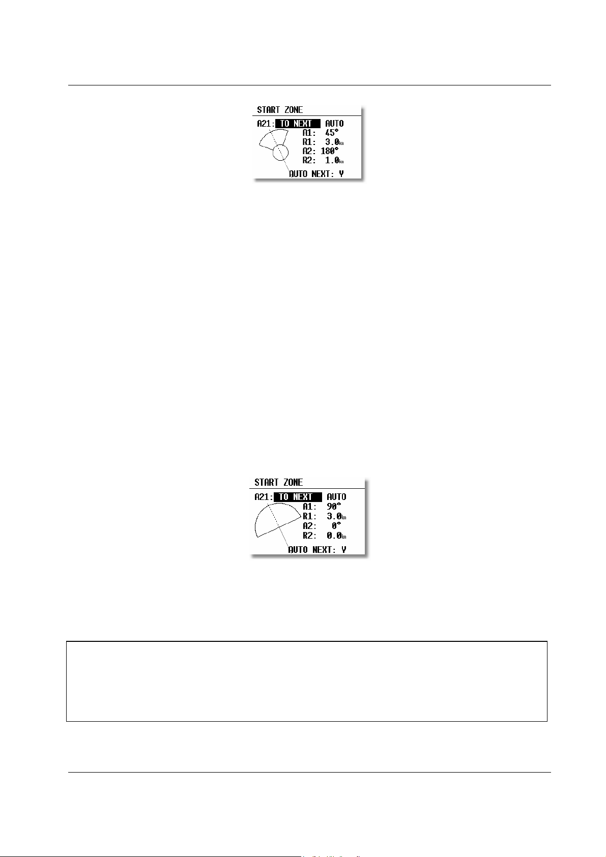
2.1.2.3.1 START ZONE
To define the start zone, select START ZONE and press ENTER. The following default screen will be displayed:
Page 14
LX 7007 pro IGC V1.0 Apr.2005
• A21: Orientation ( Options: TO NEXT, RAD.1. TP, and USER VALUE). If TO NEXT or RAD.1.TP are
selected, then AUTO is also displayed not permitting any rotation. If USER VALUE is selected, the
sector can be rotated.
• A1: First angle
• R1: Radius of the sector having angle A1, e.g. 3km for the FAI photo sector.
• A2: Like A1, used for creating combined sectors.
• R2: Like R1, also used for combined sectors
• AUTO NEXT (Y,N) defines the change over procedure on reaching the sector.
At first, this sounds complex, but the following examples will help to clarify the meaning of these settings.
Example 1:
The default setting shown above defines the FAI 90° photo sector combined with a 1km radius cylinder. To modify
these settings to set the FAI 90° photo sector as the start zone, the parameters are modified as follows:
A21 is set to TO NEXT POINT and AUTO as the start zone wants to be orientated symmetrically about the track to the
first turn point.
A1 is 45°, because the bisector of the FAI 90° sector is needed.
R1 is 3km, the radius of the sector.
A2 and R2 are both 0 as a combined sector is not needed .
Example 2:
Program a 180°, 6km Start Zone:
A21: TO NEXT POINT and AUTO
A1: 90
°
bisector
R1: 3km radius
A2: 0
R2: 0
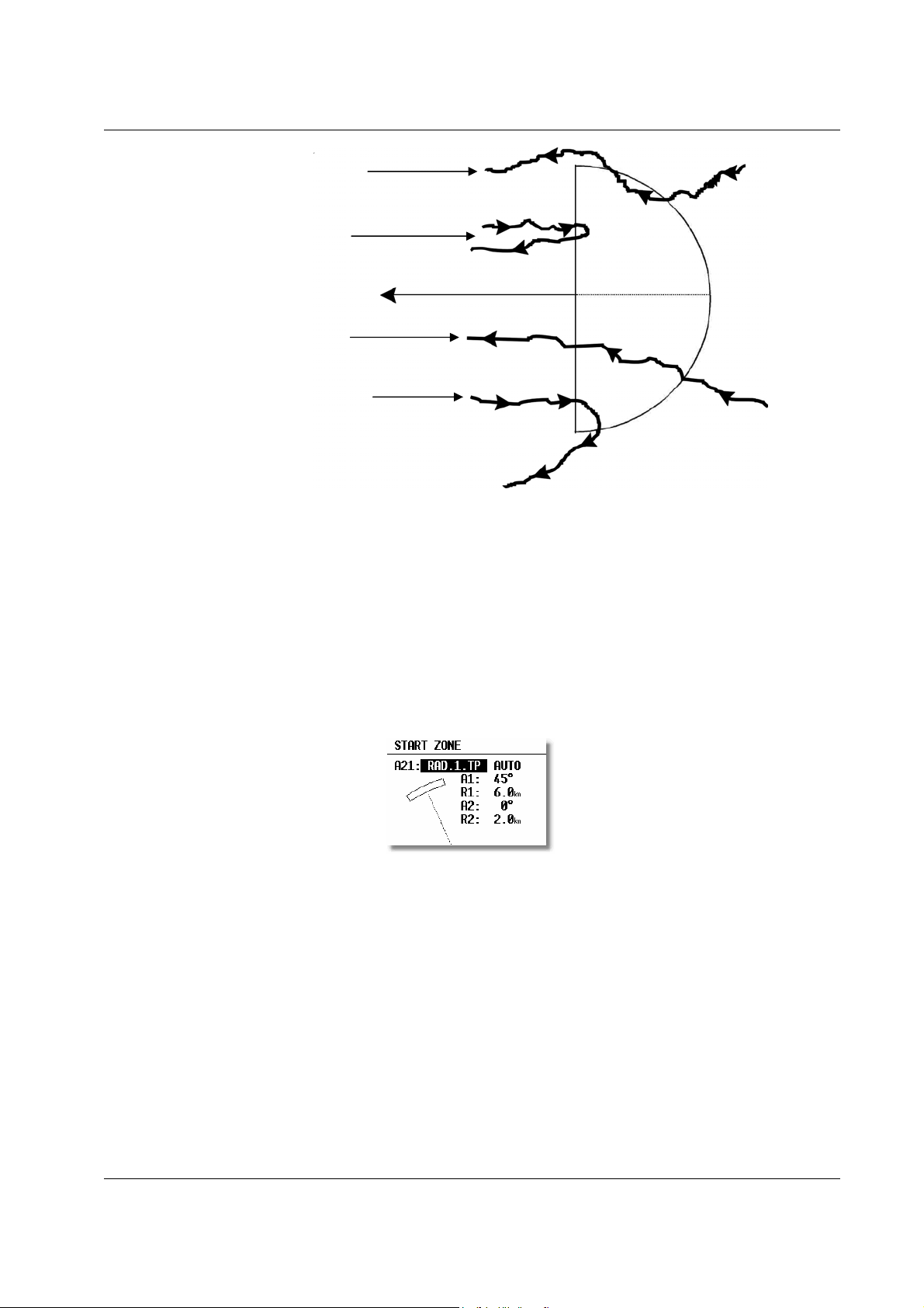
The IGC competition rules of May 2000 specify the start sector for international championships to be a straight line
perpendicular to the first track. This particular option cannot be defined in the LX 7007 PRO IGC and the 180° start
sector is programmed as Example 2 above. The only disadvantage of this is that the LX 7007 PRO IGC will record
a good start when the there is a fix recorded in the zone, whereas in reality a good start is only made when the start
line is crossed in the right direction. The diagram below illustrates this:
Note!:
Page 15
LX 7007 pro IGC V1.0 Apr.2005
Start 1: not valid with start
Start 3: valid with start
Start 4: not valid with start
It is therefore recommended that the graphics page is displayed during the start procedure to ensure that a good start is
achieved.
Other possible options for the setting of A21 are:
• RAD.1.TP: This type of start sector was used in the 1999 World Gliding Championships in Bayreuth. A radius is
drawn from the first turn point, through the start point and a second, greater radius is drawn, thus creating a radial
segment of defined length orientated symmetrically about the start point. The advantage of this system is that a
pilot starting at the extremity of the sector has to fly the same distance to the first turn point as a pilot starting
directly over the start point. This refinement compares with the classical start line where the distance to the first
turn point is increased the further one starts from the centre of the line.
A21: RAD.1.TP and AUTO are selected
A1: This setting is ignored; only R1, which defines the length of the segment, is relevant
R1: Set to 6km, the half-length of the segment, giving a total segment length of 12km
A2: Again, this setting is ignored
R2: This sets the length of the two truncated radials that define the edges of the start sector. The setting is
2km in this example
• FIXED VALUE: This setting allows the bearing of the bisector to be rotated so that it is no longer aligned with
the track to the first turn point. The required bearing is entered in A21 after FIXED VALUE:. This option is
rarely used for start sectors, but is often used for finish zones which may require to be orientated to a particular
runway (see “FINISH ZONE”).
Page 16
LX 7007 pro IGC V1.0 Apr.2005
b
(
All the examples discussed are intended to explain the programming procedures and present capability of the LX 7007
PRO IGC and do not claim to be comprehensive. Each competition will have its own rules regarding the definition of
sectors, which can be found in the particular competition rules. In case of doubt, the rules defined in the FAI Sporting
Code Section 3 should be used. In most national decentralised championships, FAIand the Barron-Hilton-Cup, only the 90
for recording the start time.
0
FAI photosector is allowed, while for record flights a 1000m startline is used
Note!:
adges, 1000/2000km diplomas
2.1.2.3.2 POINT ZONE
This setting defines the turn point zone, sometimes referred to as the observation zone. The procedure is very similar to
setting the START ZONE except that more options are available for A21.
• SYMMETRICAL: The axis of the turn point zone is orientated symmetrically about the line bisecting the inbound
leg from the previous turn point and the outbound leg to the next turn point.
• TO PREV POINT: The axis of the turn point zone is orientated towards the previous turn point. This option is
intended for Cat’s Cradle and related tasks.
• TO NEXT POINT: The axis of the turn point zone is orientated towards the next turn point. This option is also
intended for Cat’s Cradle.
• TO START POINT: The axis of the turn point zone is orientated towards the start point. Again, this is a Cat’s
Cradle option.
• FIXED VALUE: The axis of the turn point zone can be orientated in any specified direction. This is the only
option for which A21 is not set to AUTO.
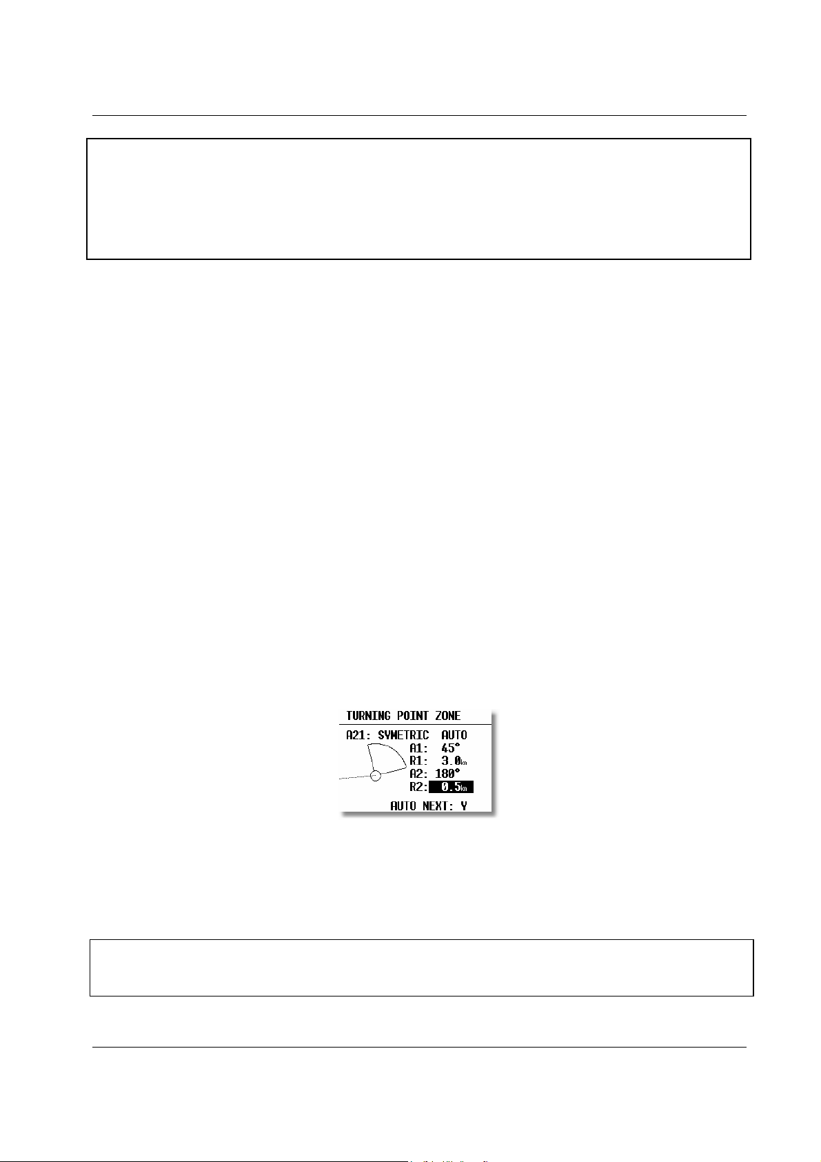
Example 3:
To specify a turn point zone that is a combination of the FAI 90° photo sector and a 500m radius cylinder:
HDG: SYMMETRICAL
A21: AUTO
A1: 45
R1: 3.0km
A2: 180
°
°
R2: 0.5km
It should be noted that when defining combined sectors, the sector with the smaller radius must be designated by A2
and R2
ie. R1>R2!).
Note!:
Page 17
LX 7007 pro IGC V1.0 Apr.2005
While the combined sector is used in many National competitions, it is emphasised that for record flights, FAI badges,
1000/2000km-diplomas and for the Barron-Hilton-Cup, only the FAI 90°-photo sector is valid!
Note!:
2.1.2.3.3 FINISH ZONE
This setting defines the FINISH ZONE or Line. Highlight the FINISH ZONE with the cursor and on pressing
ENTER, a similar screen as for the previous settings is displayed, except that there are only two options for A21:
• TO LAST LEG: The axis of the FINISH ZONE is orientated directly back to the last turn point. This is the
conventional setting for National competition flights.
• FIXED VALUE: The axis of the FINISH ZONE can be orientated in a specified direction (see example 4).
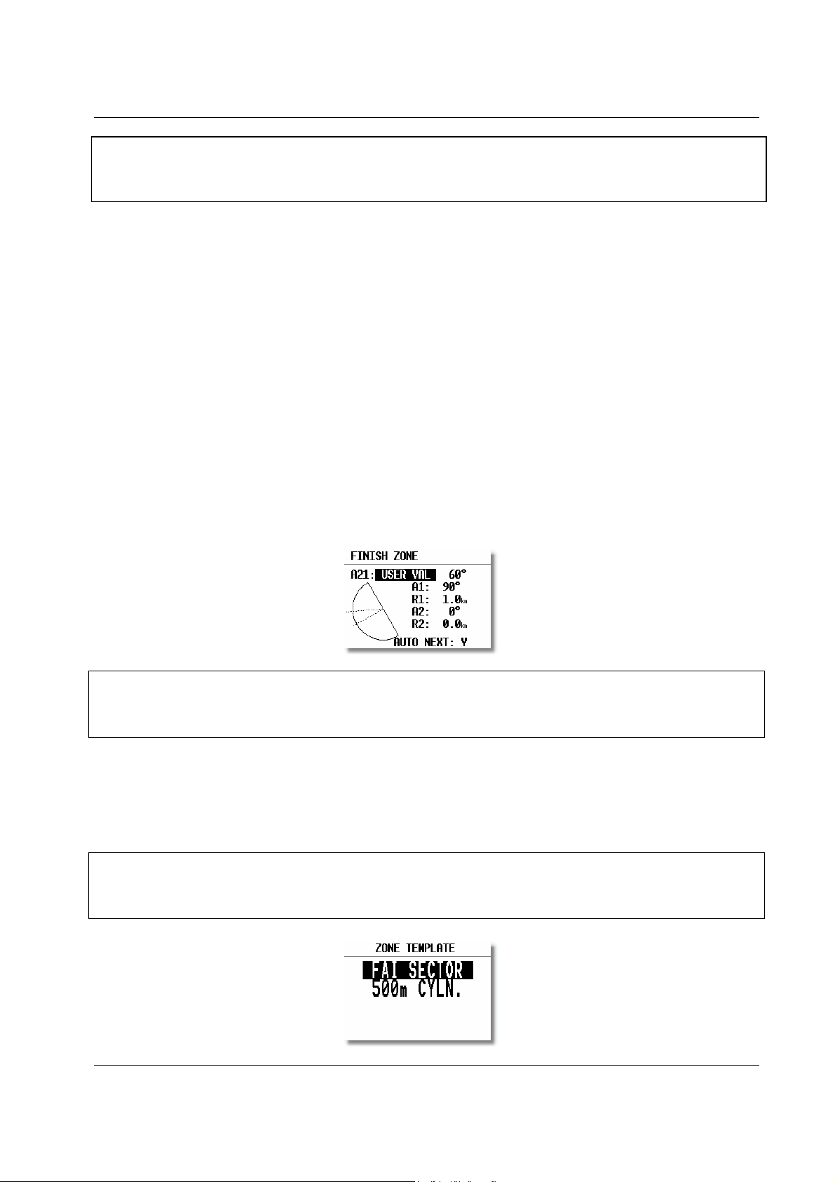
Example 4:
It is required to orientate the finish line perpendicular to the runway 06/24, which is not related to the bearing to the last
turn point:
A21: Select FIXED VALUE and then enter either 060° or 240°, depending on the direction of the final glide. For
example, if the final glide was in direction 240°, then 060° would be entered. The “flat side” of the sector is now
directed back to the last leg and the glider will cross the line to enter the sector.
A1: 90°
R1: 1.0km
A2: 0 (not programmed)
R2: 0 (not programmed)
Note!:
There are many ways to complete a flight. For instance, when completing flights for FAI badges or diplomas, it is
enough to land inside the airfield boundary if the airfield is the finish point. If a remote finish point is specified, then the
appropriate sector must be used. If in doubt, consult the competition rules of the FAI Handbook as appropriate.
2.1.2.3.4 TEMPLATES
Selecting TEMPLATES will give the choice to select one of two options: the 500m radius cylinder; or the FAI 90°
Photo Sector. When one of these templates is selected, then all the sectors of all tasks will be overwritten with the
chosen template without any further confirmation!
Note!:
An exception to this global use of TEMPLATES is when the ZONE function has been already activated. Use of
TEMPLATES in this situation will not change sectors already modified. However, using RESTORE ALL will
change all sectors, both AAT and non AAT, to the settings selected in OBS ZONES for start, TP and finish sectors
Page 18
LX 7007 pro IGC V1.0 Apr.2005
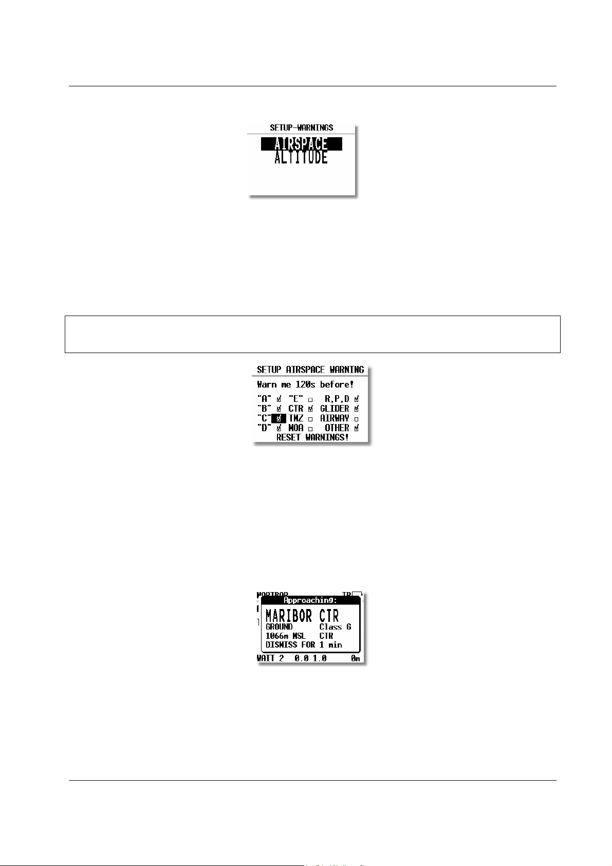
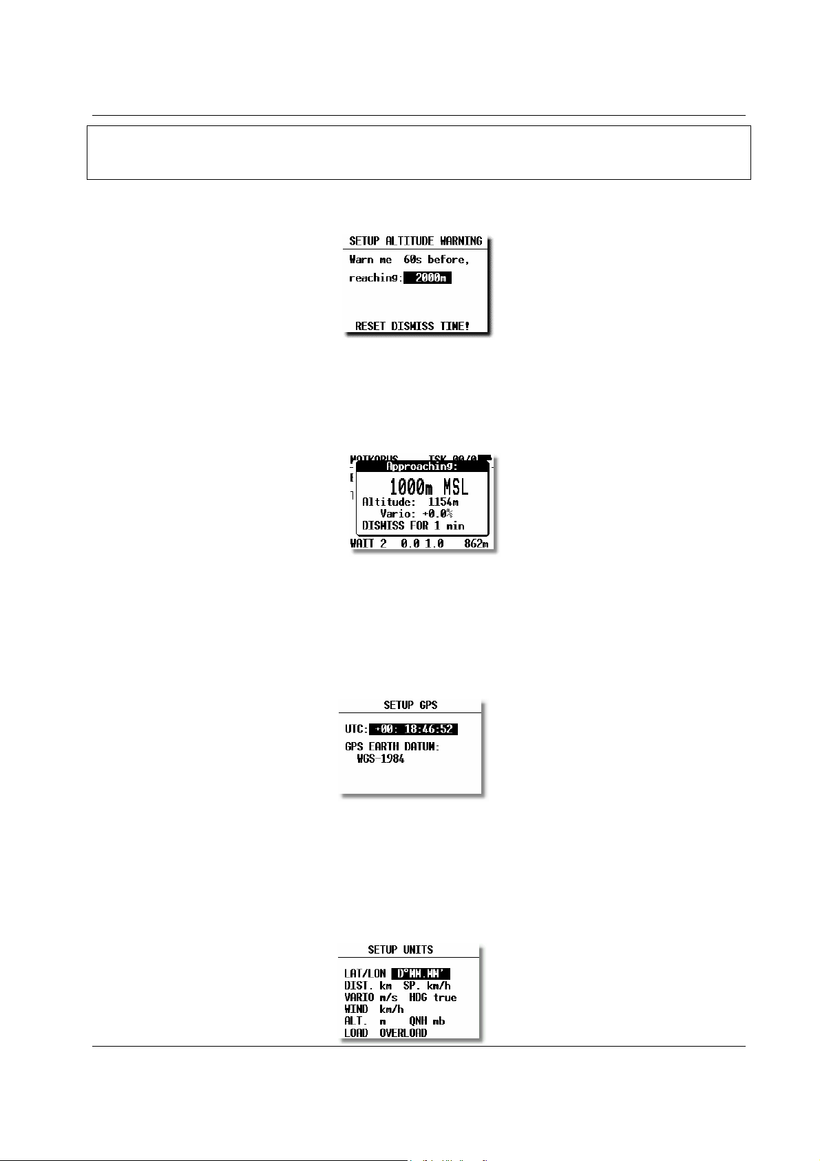
2.1.2.4 WARNINGS - Airspace Penetration and Height Warnings
The LX 7007 pro IGC monitors the glider’s position both horizontally and vertically in relation to SUA, and will give
both an acoustic and visual warning prior to the airspace being penetrated. The warning will be activated a specified
number of seconds before entering the airspace – Warn me xxx seconds before, where XXX is the desired input
between 20 and 600 seconds. The default value is 120 seconds. When thermalling, the wind vector is used to calculate
the horizontal warning and the achieved climb rate used to calculate the vertical warning. The warning calculation takes
into account the specified lower and upper airspace heights and no warning will be given if the predicted flight path is
over or under the airspace height limits. The airspace zones for which warnings are required are set by placing a tick in
the appropriate box as shown below.
Note!:
Setting “Warn me 120s before” will warn the pilot that the glider will enter airspace in two minutes provided that the
horizontal and vertical speeds are not changed.
Checked airspace (9) will cause warnings to be given, and vice versa. Airspace is selected according to the ICAO
airspace classifications of A to E. In addition the following other airspace areas can be selected
• CTR control zone
• MTZ mandatory transponder zones
• MOA military operating area
• R,P,D restricted, prohibited, dangerous zones
• GLIDER glider activity zones
• AIRWAYS airways
• OTHER
Example of an airspace warning
The DISMISS warning can be used to deactivate the particular airspace warning for a period of time. Use the
UP/DOWN selection to enter the duration for which the warning is required to be deactivated and press ENTER. The
displayed airspace warning can be DISMISSed from 1 minute to permanent de-activation. DISMISS selections can
subsequently be cancelled by using RESET WARNINGS in the SETUP/Warnings screen. Once the warnings have
been reset, they can be DISMISSed again if the pilot so desires.
Page 19
LX 7007 pro IGC V1.0 Apr.2005
Note!:
Use the DISMISS function to temporarily deactivate individual airspace warnings. All warnings can be reinstated
using the RESET WARNINGS command in the SETUP/Warnings screen.
ALTITUDE warnings can be setup in a similar way and inform the pilot that he is approaching pre-selected altitude
limits.
The warning altitude is always above MSL (Mean Sea Level). The warning will be activated at a specific time before
reaching the altitude limitation. While thermalling, the achieved climb rate is used to calculate when the warning
altitude is going to be reached and similarly, in straight flight, the descent rate is the controlling parameter. Operation
of the altitude warning is the same as for the airspace warning and use of the DISMISS and RESET DISMISS TIME
commands are identical.
Example: altitude warning
2.1.2.5 SETUP GPS
UTC: A UTC offset can be entered at this option, thus ensuring that all time references are to local time rather than
UTC. However, it should be remembered that any offset will have no effect on the time recorded in the IGC flight log;
this will always be UTC
GPS EARTH DATUM: It is not possible to change the GPS earth datum. IGC regulations require that all flight
recorders use the WGS84 earth datum.
2.1.2.6 UNITS
All known units and combinations thereof can be programmed in the LX 7007 PRO IGC. The various units that can be
selected are outlined below:
Page 20

LX 7007 pro IGC V1.0 Apr.2005
• LAT/ LON: degrees and decimal minutes; or degrees, minutes and seconds
• DIST: kilometers (km); nautical miles (NM); or statute miles (ml)
• SP (Speed) kilometers per hour (km/h); knots (kts); or statute miles per hour (mph)
• VARIO: meters per second (m/s); or knots (kts)
• HDG: degrees magnetic ( °M) or degrees true (°T)
• WIND: kilometers per hour (km/h); knots (kts); miles per hour (mph); or meters per second (m/s)
• ALTITUDE: meters (m); or feet (ft)
• QNH: millibars (mb); millimeters of mercury (mm); or inches of mercury (in)
• LOAD: Overload; kilograms per sq meter (kg/m
2
); or pounds per sq foot (lb/ft2 )
Glider + Pilot + Ballast
OVERLOAD = --------------------------------
Glider + Pilot
Example:
An overload of 1.2 means that the current ballasted flight weight is 20% higher than the unballasted flight weight.
2.1.2.7 GRAPHIC
The graphic display of the LX 7007 PRO IGC can show a lot of information and if it is all selected, the display can
become very cluttered. This particularly applies to airspace information and the user should ensure that only relevant
airspace is selected. It should also be remembered that a cluttered display also increases the load on the graphical
processor and slows down the rate at which the screen is redrawn.
SETUP SYMBOL
The LX 7007 PRO IGC graphic display supports two sizes of glider symbol; large and small. Rotate the UP/DOWN
selector to select the corresponding glider symbol. TAIL LENGTH enables a ‘mouse droppings trail’ to be configured
that will display the achieved track for the last x minutes. The trail is disabled if the time period is set to zero.
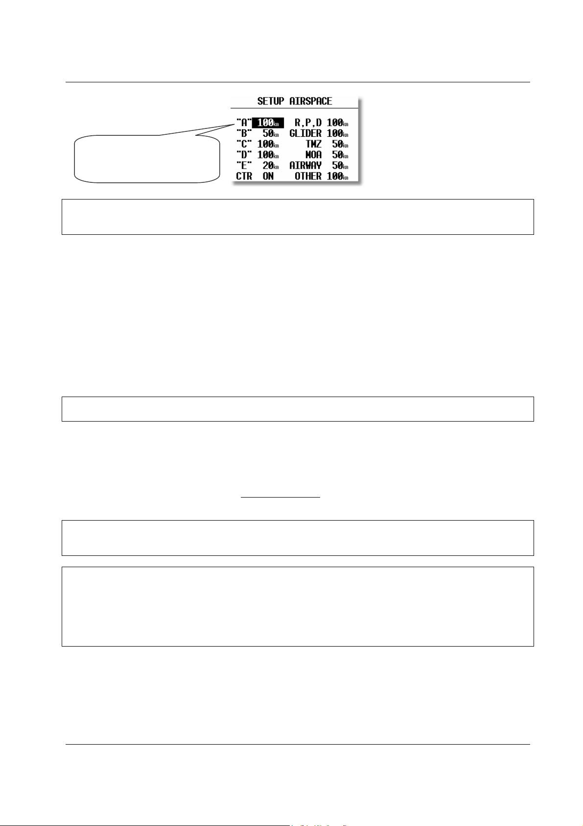
AIRSPACE
This setting allows the pilot to define which airspace types will be shown on the display. Each airspace type can be set
to ON, OFF or a ZOOM range beyond which the particular airspace will not be displayed. Selecting ON will always
show the airspace regardless of the ZOOM setting, and OFF will never show the airspace. If all airspace is set to ON,
then at large ZOOM ranges, the screen becomes very cluttered and the graphics processor will become overloaded and
slow down. To prevent this happening, the ZOOM range option allows a range to be set, beyond which the airspace
will not be displayed.
Page 21
LX 7007 pro IGC V1.0 Apr.2005
Class A will only be shown
when the ZOOM scale is
100km or lower
Note!:
If, for instance, 100 km is selected, then the airspace will only be shown when the ZOOM range is 100 km or lower.
When the ZOOM range is greater than 100 km, the particular airspace will not be shown.
The LX7000 allows the following types of airspace to be shown:
• Class A
• Class B
• Class C
• Class D
• Class E
• CTR. Control zone
• R.P,D Restricted, Prohibited and Danger areas
• GLIDER
• TMZ Transponder mandatory zones
• MOA Military operating areas
• AIRWAY
• OTHER
Note!
CTRs are marked using a bold line, so the pilot is able to separate CTRs from other airspace very quickly.
Airspace Customization
A completely new feature of the LX 7007 pro IGC V2.0 is that pilots can customize their own airspace files. Pilots are
able to create areas, or to add and remove particular airspace according to their personal requirements. All
customization is done using the well known “Open Air format” or “Tim Newport Piece format”. Detailed
instructions on customization are described in a separate document, the LxasBrowser manual. This manual is supplied
with each instrument and is also available on www.lxnavigation.si
. Restricting the creation of airspace to a dedicated
area where the pilot is usually flying will make the instrument much faster when operating the ZOOM function.
Note!:
All airspace files used with LX7000 v2.0 must have the .CUB extension; it is not possible to load old airspace format
files. The new airspace files can be created and loaded using Lxe build July 15th 2003 or later.
Note!:
To be able to use all the benefits of the airspace graphics and warnings, it is recommended that some time is taken to
study the airspace of the task area. All irrelevant zones should be deleted so that the speed of graphical presentation
remains fast and unnecessary airspace warnings are avoided. Some TMAs are built from many sectors and is
recommended that these sectors are amalgamated into one large TMA definition, if possible. After modification of
.LXW files it is essential that a new .CUB file is built. LXW is a new airspace data base format described in the
LxasBrowser manual or on the www.lxnavigation.si website.
APT GRAPHICS (Airports)
Airports are displayed with aerodrome symbols together with their name which can be configured in variety of ways.
Page 22
 Loading...