

Page 1
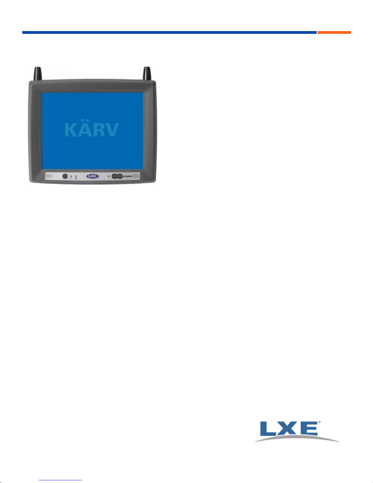
Kärv User Guide
LXE | TRUX | Vehicle-Mount Computer
E-EQ-VX8OGWW-G
Copyright © 2011 by LXE®, Inc. LXE is now part of Honeywell. All Rights Reserved.
Page 2

Notices
LXE Inc. reserves the right to make improvements or changes to published Kärv information at any time without notice. While
reasonable efforts have been made in the preparation of this publication to assure its accuracy, LXE assumes no liability
resulting from any errors or omissions in this publication, or from the use of the information contained herein. Further, LXE
Incorporated, reserves the right to revise this publication and to make changes to it from time to time without any obligation to
notify any person or organization of such revision or changes.
Trademarks
Copyright © 2011 by LXE Inc., LXE is now part of Honeywell, 125 Technology Parkway, Norcross, GA 30092 U.S.A. (770)
447-4224
LXE® and Spire® are registered trademarks of LXE Inc.
RFTerm® is a registered trademark of EMS Technologies, Norcross, GA. EMS is now part of Honeywell.
Microsoft®, ActiveSync®, MSN, Outlook®, Windows®, Windows Mobile®, the Windows logo, and Windows Media are
either registered trademarks or trademarks of Microsoft Corporation in the United States and/or other countries.
Intel and Intel XScale are trademarks or registered trademarks of Intel Corporation or its subsidiaries in the United States and
other countries.
Summit Data Communications, Inc. Summit Data Communications, the Summit logo, and “The Pinnacle of Performance” are
trademarks of Summit Data Communications, Inc.
The Bluetooth® word mark and logos are owned by the Bluetooth SIG, Inc. and any use of such marks by LXE, Inc. is under
license.
Bluetooth and GSM technology are not available in Brazil. Bluetooth e tecnologia GSM não estão disponíveis no Brasil.
PowerScan is a registered trademark of Datalogic Scanning, Inc., located in Eugene, OR.
Symbol® is a registered trademark of Symbol Technologies. MOTOROLA® and the Stylized M Logo are registered
trademarks of Motorola®, Inc.
Wavelink®, the Wavelink logo and tagline, Wavelink Studio™, Avalanche Management Console™, Mobile Manager™, and
Mobile Manager Enterprise™ are trademarks of Wavelink Corporation, Kirkland.
Qualcomm® is a registered trademark of Qualcomm Incorporated. Gobi is a trademark of Qualcomm Incorporated.
OneClick Internet is WebToGo’s patented connection manager customized for LXE mobile devices. OneClick Internet
documentation is copyright 2010 by WebToGo and modified by LXE with WebToGo’s express permission.
Verizon® is a registered trademark of Verizon Trademark Services LLC.
When any part of this publication is in PDF format: “Acrobat ® Reader Copyright © 2011 Adobe Systems Incorporated. All
rights reserved. Adobe, the Adobe logo, Acrobat, and the Acrobat logo are trademarks of Adobe Systems Incorporated”
applies.
Other product names mentioned within this publication may be trademarks or registered trademarks of other companies.
Page 3

Table of Contents
Set Up A New Kärv 1
Hardware Setup 1
Software Setup 1
Components 2
Top View 2
Bottom View 3
Indicators and Buttons 4
Tapping the Touchscreen with a Stylus 5
LED Indicators 6
Power LED 6
UPS Mode LED 6
Hard Drive LED 6
Keyboard LEDs 7
CAPS LED (60 key keyboard) 7
Secondary Keys LED (60 key keyboard) 7
Connecting Cables to the Kärv 8
Removing the Port Lid 8
Connect Keyboard 8
Connect USB Devices 10
Connect Ethernet Cable 10
Connect Serial Barcode Scanner 11
External AC Power Supply, Optional 12
Connect External Headset 12
Connecting Vehicle Power 12
How To: Connect Vehicle Electrical Connection 14
Connection without Screen Blanking 16
Connection with Screen Blanking Box 17
Connection with Relay/Mechanical Switch for Screen Blanking 18
Connect Multipurpose Cable 19
Securing Port Lid 20
Kärv Configuration Options 21
Date and Time 21
Power Management 21
Speaker Volume 21
Connect Bluetooth Devices 21
Restart/Shutdown 22
Soft Keyboard 22
E-EQ-VX8OGWW-G [ i ] Kärv User Guide
Page 4

Table of Contents
Calibrate Touchscreen 22
Cleaning the Touchscreen and Scanner Aperture 23
Apply the Touchscreen Protective Film 23
Setup Terminal Emulation Parameters 23
Regulatory Notices and Safety Information 24
Class A Digital Device 24
RF Safety Notice 25
Lithium Battery Safety Statement 26
Vehicle Power Supply Connection Safety Statement 27
Revision History 28
Index 29
E-EQ-VX8OGWW-G [ ii ] Kärv User Guide
Page 5

Set Up A New Kärv
The Kärv is also known as the VX8.
Note: LXE recommends that installation or removal of accessories be performed on a clean, well-lit surface. When
necessary, protect the work surface, the Kärv, and components from electrostatic discharge.
While the Kärv is in a Hazardous Location DO NOT:
l Connect an external power source to the Kärv.
l Connect a USB device or audio jack to the Kärv.
l Connect a tethered scanner to the Kärv.
Hardware Setup
1. Connect accessories.
2. Connect power cable.
3. Secure all cables to the Kärv with the Strain Relief Cable Clamps.
4. Press the Power key.
Software Setup
Prerequisite: Hardware setup is complete.
Information in this guide includes instruction for all Kärv operating systems. Differences are highlighted as follows:
Windows® 7 Professional
Windows® Embedded Standard
Windows® XP Embedded / Professional
Software configuration options
E-EQ-VX8OGWW-G [ 1 ] Kärv User Guide
Page 6
Components
Components
Top View
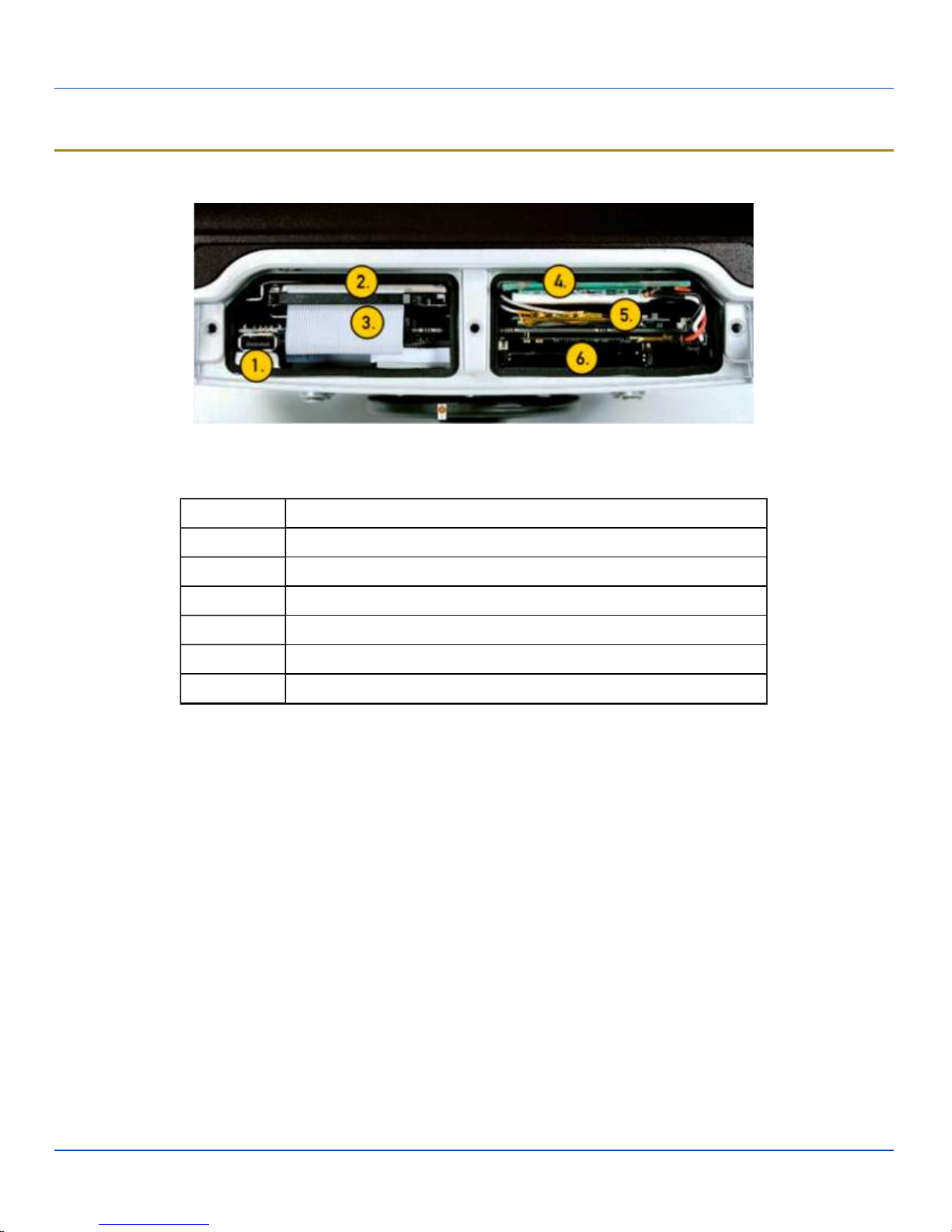
Kärv Components, Top
The service lid has been removed to show components.
Position Function
1 USB 2.0
2 Hard drive
3 Compact Flash slot, optional (behind HD cable)
4 Battery/UPS
5 Mini PCI slot
6 PC Card slot (option)
E-EQ-VX8OGWW-G [ 2 ] Kärv User Guide
Page 7
Bottom View
Bottom View
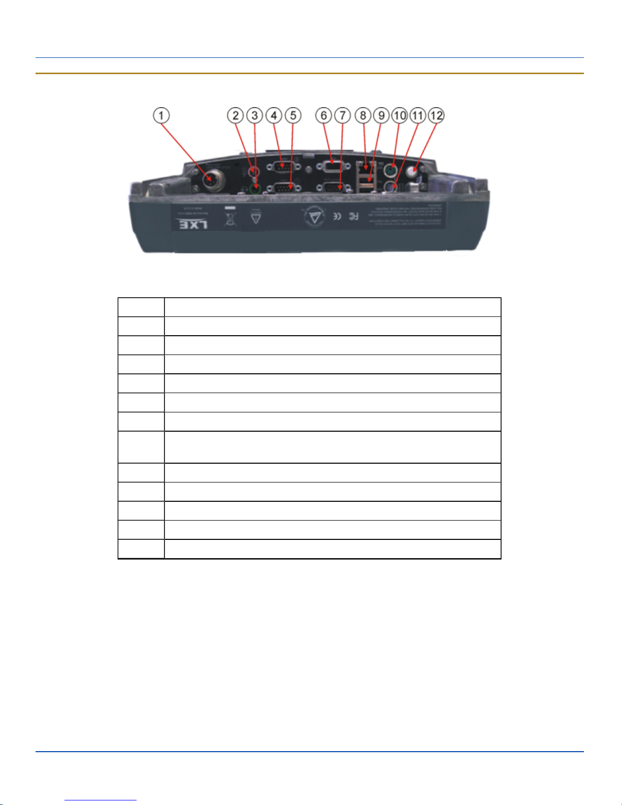
Kärv Components, Bottom
Position Function
1 Power supply (12V DC 50W)
2 Mic. in
3 Audio out
4 COM2 RS232 +12V
5 COM1 RS232 +5V
6 VGA (external monitor)
Multipurpose Connection (provides USB, COM4 with optional +12V on pin 9
7
or both with optional cable)
8 RJ-45 Ethernet 10/100 (LAN)
9 2x USB 2.0
10 PS/2 Mouse
11 PS/2 Keyboard
12 Bluetooth antenna connector
E-EQ-VX8OGWW-G [ 3 ] Kärv User Guide
Page 8
Indicators and Buttons
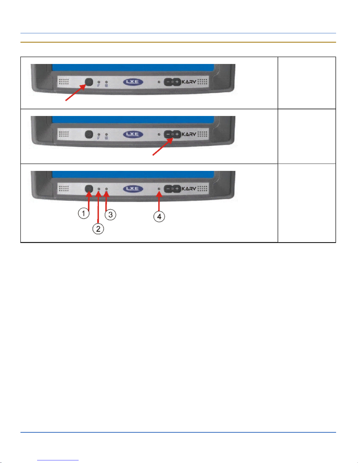
Indicators and Buttons
On/Off Button
Screen Brightness
1. Power LED
2. UPS Mode
LED
3. Hard Drive
LED
4. Light Sensor
Kärv Components, Front
E-EQ-VX8OGWW-G [ 4 ] Kärv User Guide
Page 9

Tapping the Touchscreen with a Stylus
Tapping the Touchscreen with a Stylus
Note: Always use the point of the stylus for tapping or making strokes on the touchscreen.
Never use an actual pen, pencil, or sharp/abrasive object to write on the touchscreen.
Hold the stylus as if it were a pen or pencil. Touch an element on the screen with the tip of the stylus then remove the stylus
from the screen.
Firmly press the stylus into the stylus holder when the stylus is not in use.
Using a stylus is similar to moving the mouse pointer then left-clicking icons on a desktop computer screen.
Using the stylus to tap icons on the touchscreen is the basic action that can:
l Open applications
l Choose menu commands
l Select options in dialog boxes or drop-down boxes
l Drag the slider in a scroll bar
l Select text by dragging the stylus across the text
l Place the cursor in a text box prior to typing in data
l Place the cursor in a text box prior to retrieving data using a scanner/imager or an input/output device connected to a
serial port.
A right click is generated by tapping the mouse icon in the system tray. After tapping, the mouse icon highlights the
right button of the icon in red. The next touchscreen tap is treated as a right click. The mouse icon returns to the left
button highlighted in red so subsequent taps are treated as left clicks.
A stylus replacement kit is available.
E-EQ-VX8OGWW-G [ 5 ] Kärv User Guide
Page 10
LED Indicators
LED Indicators
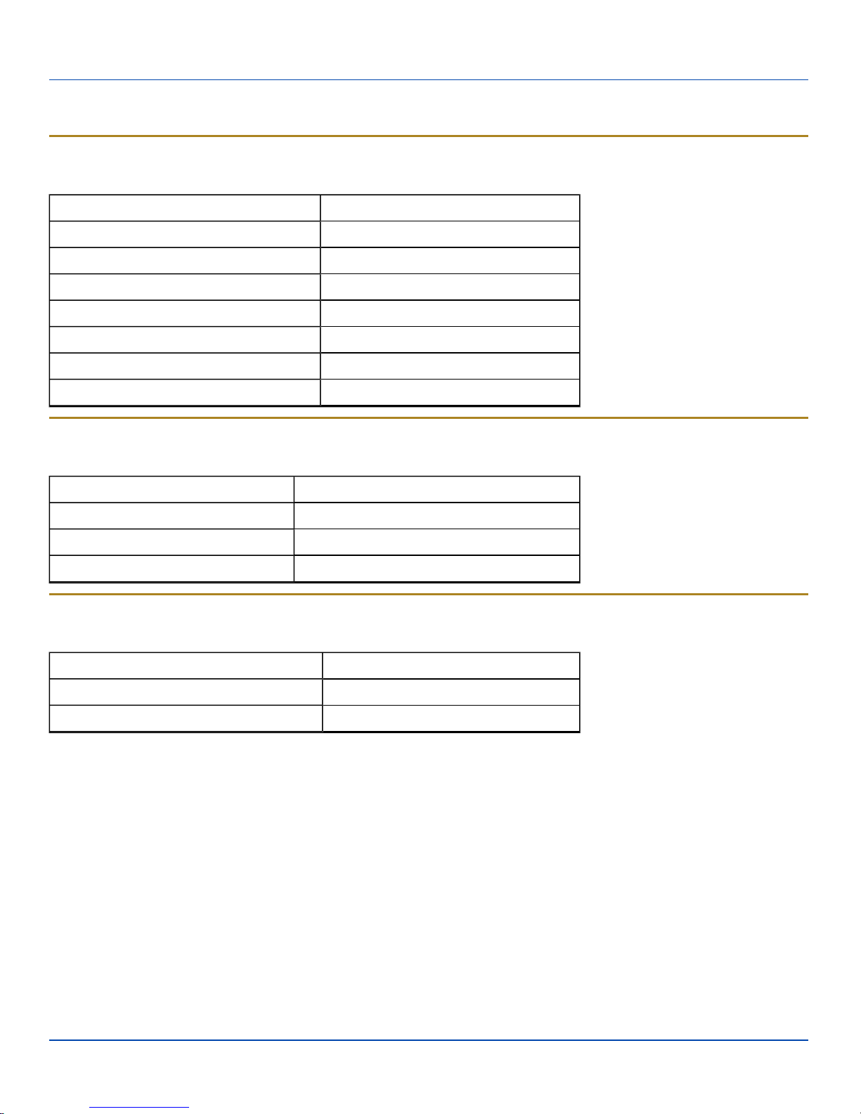
Power LED
The Power LED is incorporated into the power button.
Function Power LED
Off and not powered Off (no light)
Off but powered Green flash very slow
Operating normally Green on
Suspend Green flashing slow
Black-out Screen Green flashing fast
Over voltage shutdown Red on
Over temperature Red flashing
UPS Mode LED
The UPS Mode LED is to the immediate right of the power button.
Function UPS Mode LED
UPS battery powered Green flashing fast
UPS battery charging Green on or flashing slow
UPS battery charged Off (no light)
Hard Drive LED
The Hard Drive LED is located to the right of the UPSMode LED.
Function Hard Drive LED
Hard drive activity Green flashing
No activity Off (dark)
E-EQ-VX8OGWW-G [ 6 ] Kärv User Guide
Page 11

Keyboard LEDs
Keyboard LEDs
The Kärv with 60 key keyboard has two keyboard LEDs located above the Enter key and between the alpha keypad and the
numerical keypad.
The Kärv with 95 key keyboard does not use LEDindicators. Instead the backlight color of the CapsLock and NumLock keys
are used to indicate the status. When CapsLock, NumLock or Scrol Lock is enabled, the corresponding key is backlit in
amber. When off, the key is backlit in green.
CAPS LED (60 key keyboard)
This LED indicates the state of the keyboard CapsLock mode. If CapsLock is enabled this LED is illuminated green. When
CapsLock is off, the LED is dark.
Press <2nd> then <F1> to toggle CapsLock On and Off. The default value of CapsLock is “Off”.
Secondary Keys LED (60 key keyboard)
The keyboard is equipped with several secondary keys. These keys are identified by the superscripted text found on the
keyboard keys. The secondary keys are accessible by using two keystrokes: the <2nd> key followed by the superscripted
key.
Once the <2nd> state is enabled (by pressing the <2nd> key) the Secondary Mode LED is illuminated and the <2nd> state is
enabled until another key is pressed.
The <2nd> key is toggled on with a <2nd> keypress and then immediately off with another <2nd> keypress.
For example:
l Press <2nd> and <F1> to turn CapsLock on and off.
l Press <2nd> and <↑> to initiate the PgUp command.
l Press <2nd> and <Q> to type the “!” key.
l Press <2nd> and <BkSp> to enter the Insert (Ins) mode.
E-EQ-VX8OGWW-G [ 7 ] Kärv User Guide
Page 12
Connecting Cables to the Kärv
Connecting Cables to the Kärv
Note: Do not connect or disconnect cables in a Hazardous location.
Removing the Port Lid
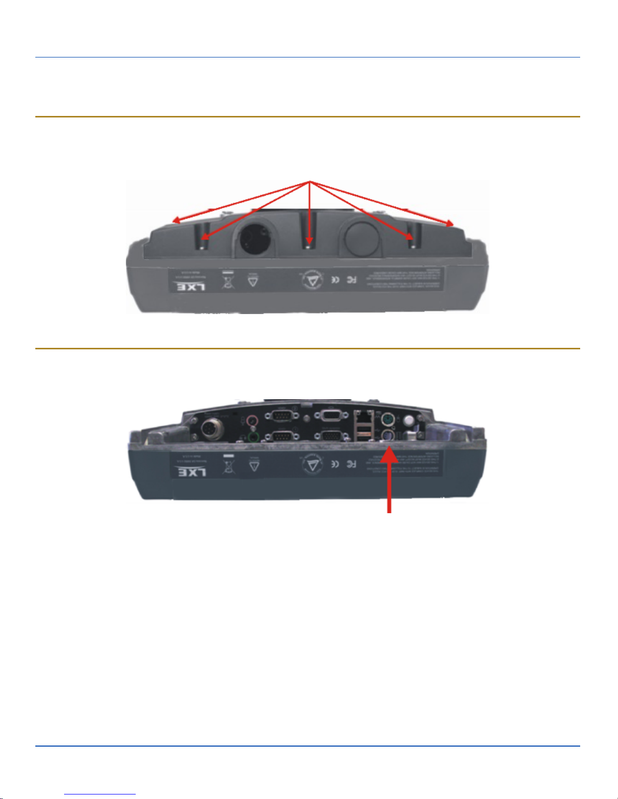
Before any cables can be attached to the Kärv, the port lid must be removed. The port lid is held in place with eight (8) Torx 20
screws. Remove the screws and the port lid and set aside for reinstallation once all accessories are attached.
Removing the Port Lid
Connect Keyboard
The Kärv has PS/2 connectors for the keyboard and mouse.
Keyboard and Mouse Connectors
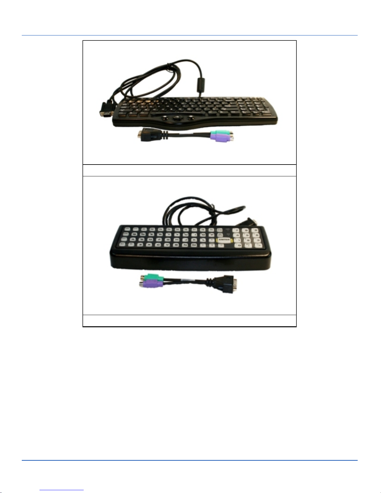
Connect the adapter cable to the PS/2 connectors on the Kärv.
Connect the LXE keyboard to the adapter cable.
E-EQ-VX8OGWW-G [ 8 ] Kärv User Guide
Page 13
Connect Keyboard
95 key with Integrated Pointing Device
E-EQ-VX8OGWW-G [ 9 ] Kärv User Guide
60 key
The LXE VMT Keyboards with Cable
Page 14
Connect USB Devices
Connect USB Devices
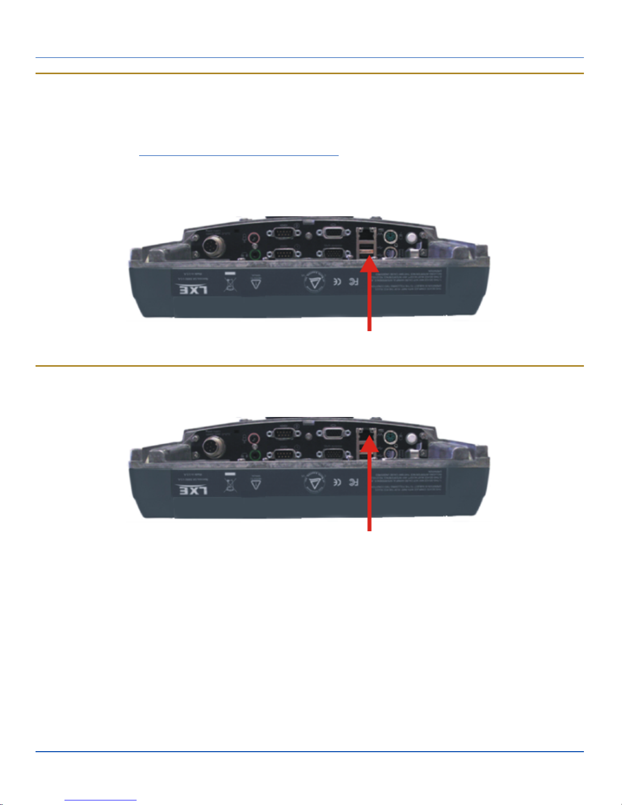
The Kärv provides the following Type A ports:
l internal USB port, accessible when the service lid is removed
l two external USB ports (see below)
l a USB port via a dongle cable attached to the multipurpose port.
Plug the desired device, such as a USB mouse or storage device, into the USB port. Refer to Start |Help and Support and
the documentation for your USB device for more information.
USB devices may be installed, removed or swapped without turning off the Kärv.
External USBPorts
Connect Ethernet Cable
Note: Use of a shielded cable is required to maintain emissions and susceptibility compliance..
Connect Ethernet Cable
1. Insert the network cable and ensure it is firmly seated in the connector jack.
2. To remove the Ethernet cable, press the release tab on the cable end.
E-EQ-VX8OGWW-G [ 10 ] Kärv User Guide
Page 15
Connect Serial Barcode Scanner
Connect Serial Barcode Scanner
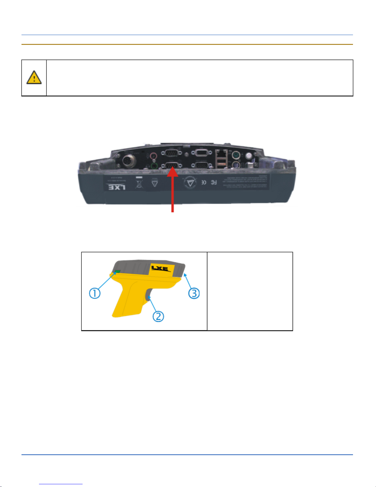
l Refer to the documentation received with the barcode scanner for complete instructions. Read all warnings
and caution labels.
l Pin 9 of COM1 provides +5V. Do not connect a serial barcode scanner to COM2 or COM4 as this may dam-
age the scanner, the Kärv or both.
Configuration of COM port power is handled via the VMT Manager option in the Control Panel. For more information consult the
Kärv Reference Guide or the system administrator responsible for the configuration of the Kärv.
The scanner cable is attached to the COM1 port. The cable requires a nine-pin D-shell female connector for the Kärv.
Note: Use of a shielded cable is required to maintain emissions and susceptibility compliance.
Connect Serial Scanner Cable
Seat the connector firmly over the pins and turn the thumbscrews in a clockwise direction. Do not overtighten.
When you have finished using the scanner, remove it from the Kärv and store the scanner in a closed container or bag.
1. Good Scan LED (or
equivalent)
2. Trigger
3. Laser Aperture at Front
Generic Barcode Scanner
Refer to the documentation received with the barcode scanner for complete instructions.
E-EQ-VX8OGWW-G [ 11 ] Kärv User Guide
Page 16
External AC Power Supply, Optional
External AC Power Supply, Optional
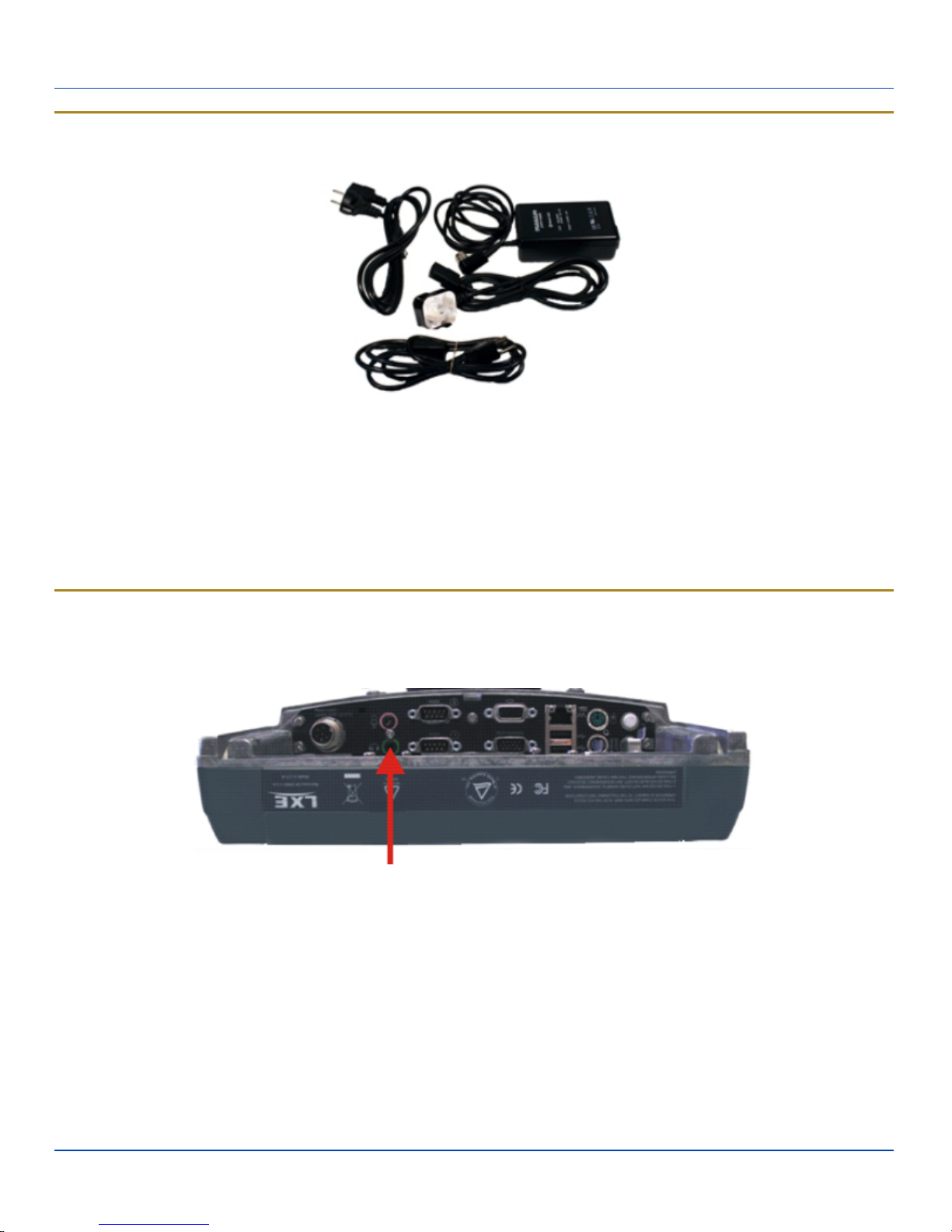
Optional AC Power Supply
1. Turn the Kärv off.
2. Connect the appropriate detachable cordset to the external power supply.
3. Plug cordset into appropriate, grounded, electrical supply receptacle (AC mains).
4. Connect the watertight connector end to the Kärv’s Power Connector by aligning the connector pins to the power connector; push down on the watertight connector and twist it to fasten securely.
5. Turn the Kärv on.
Connect External Headset
The Kärv provides an external headset connection via an audio jack connector and a microphone to a separate microphone
jack connector. The connectors are color keyed and marked with the headset and microphone symbols.
Connect External Headset
1. Insert the speaker or headphone plug into the audio connector; making sure the plug is firmly seated in the jack.
2. Insert the microphone plug into the microphone connector; making sure the plug is firmly seated in the jack.
Connecting Vehicle Power
Complete vehicle cradle mounting and power instruction is contained in the Kärv Cradle Guide.
The DC to DC converter is used to power the Kärv. The converter must be used with the Kärv regardless of vehicle voltage.
E-EQ-VX8OGWW-G [ 12 ] Kärv User Guide
Page 17
Connecting Vehicle Power
Specifications for electrical supply
Input Voltage
Output
Voltage
Always observe input voltage range specified on the DC to DC power supply and the optional screen
blanking box.
12 VDC ± 10%: models VX89301PWRSPLY, VX89A302PSDC48V, VX89303PWPSPLY
13.2 VDC ± 10%: models VX89305PWRSPLY, VX89306PWRSPLY
50 W: models VX89301PWRSPLY, VX89302PSDC48V, VX89303PWPSPLY
Power
75 W: models VX89305PWRSPLY, VX89306PWRSPLY
10 A (slow blow fuse)
Fuse
3 A (for optional screen blanking box)
Fuses are USER SUPPLIED
Please refer to the appropriate wiring schematic below for wiring colors and connections:
For proper and safe installation, the input power cable must be connected to a fused circuit on the vehicle. This
fused circuit requires a user supplied 10 Amp maximum time delay (slow blow) high interrupting rating fuse. If the
supply connection is made directly to the battery, the fuse should be installed in the positive lead within 5 inches of
the battery positive (+) terminal.
For installation by trained service personnel only.
Risk of ignition or explosion. Explosive gas mixture may be vented from battery. Work only in well ventilated area.
Avoid creating arcs and sparks at battery terminals.
E-EQ-VX8OGWW-G [ 13 ] Kärv User Guide
Page 18
How To: Connect Vehicle Electrical Connection
How To: Connect Vehicle Electrical Connection
1. Please review the proper wiring schematic illustration, later in this section, before beginning power cable install.
2. The computer must be powered off.
Begin by connecting the power cable to the Kärv. Work from this connection with the last connection being to the
3.
vehicle’s power source.
Route the cable from the Kärv to the DC to DC converter and, optionally, the screen blanking box. Cut the cable to
length and strip the wire ends. If the screen blanking box is not used, do not strip the green and yellow wires.
Route the power cable the shortest way possible. The cable is rated for a maximum temperature of 105°C (221°F).
When routing this cable it should be protected from physical damage and from surfaces that might exceed this
4.
temperature.
Do not expose the cable to chemicals or oil that may cause the wiring insulation to deteriorate.
Always route the cable so that it does not interfere with safe operation and maintenance of the vehicle.
For models VX89301PWRSPLY, VX89A302PSDC48V, VX89303PWPSPLY only:
5a.
DC to DC Converter
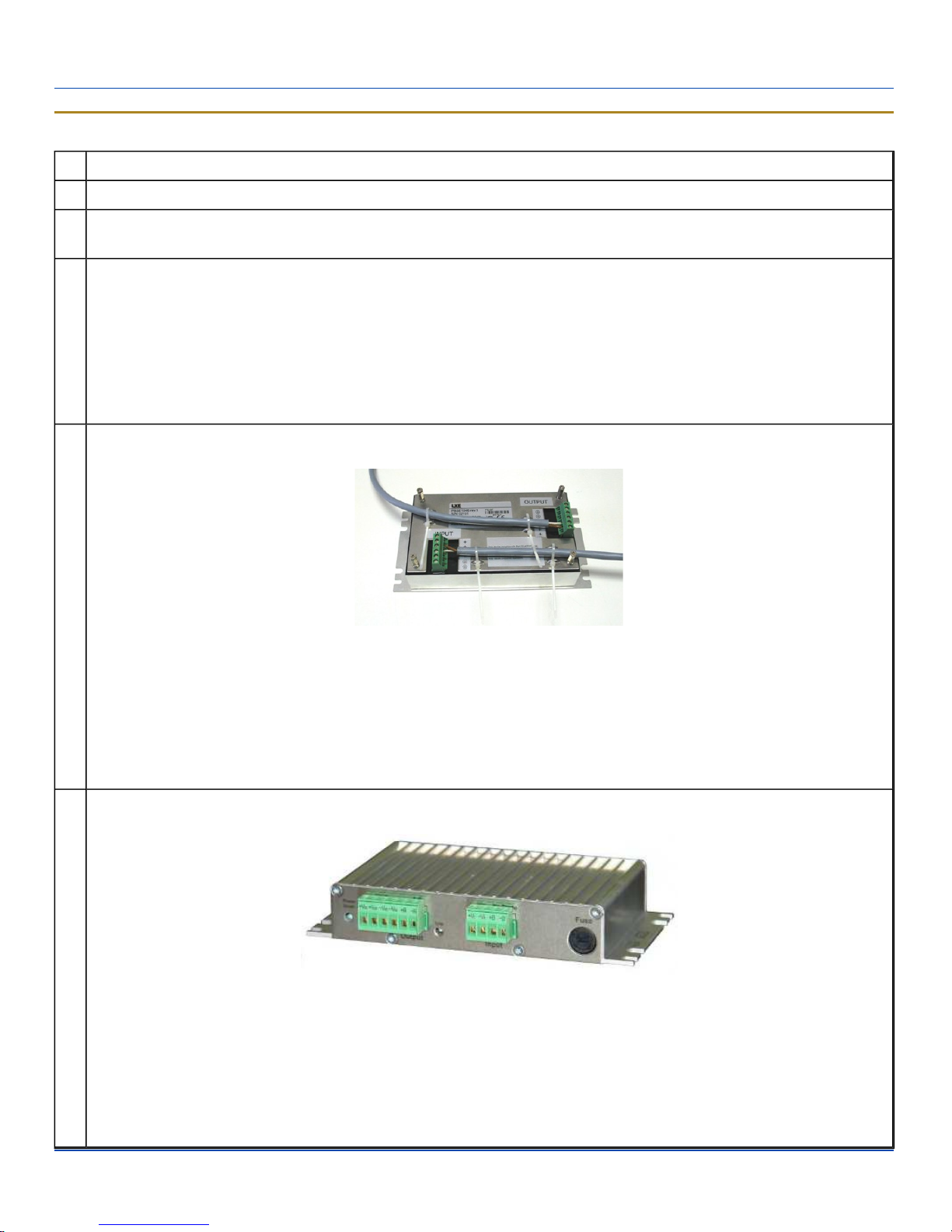
Remove the lid from the DC to DC converter. Attach the stripped wire ends to the output side of the DC to DC converter.
Attach stripped wire ends to the input side of the DC to DC converter.
The input and output blocks each have two + and two – minus connectors. Either connector in the block can be used to
connect the matching polarity wire.
Use the looms and wire ties to secure all wiring then reattach the cover with the screws.
For models VX89305PWRSPLY, VX89306PWRSPLY only:
5b.
DC to DC Converter
Attach the stripped wire ends to the output side of the DC to DC converter. Attach stripped wire ends to the input side of
the DC to DC converter.
The input block has one +Vi and one –Vi connection to connect the matching polarity wire.
The output block has two +Vo and two –Vo connectors. Either connector in the block can be used to connect the
matching polarity wire.
E-EQ-VX8OGWW-G [ 14 ] Kärv User Guide
Page 19
How To: Connect Vehicle Electrical Connection
Use wire ties to secure all wiring, providing strain relief for the power supply connections.
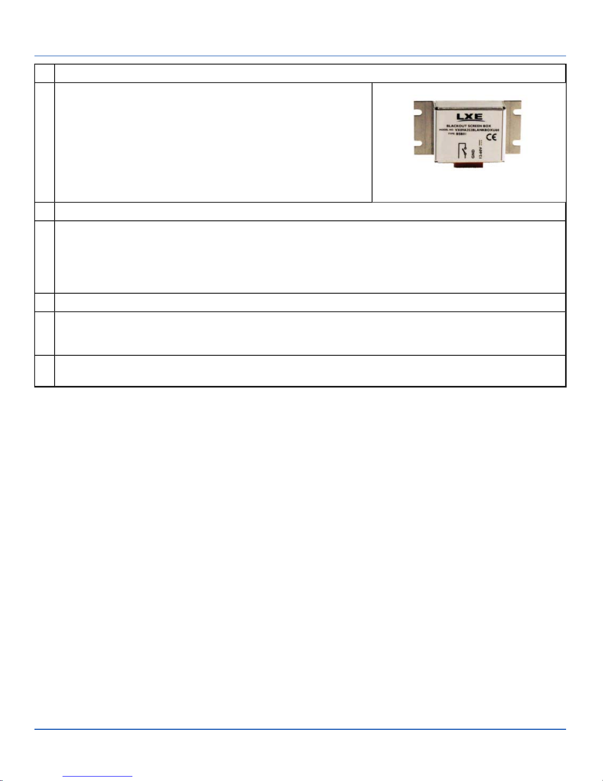
If the screen blanking box is used for the Kärv installation, attach the
6.
stripped wire ends to the box. Refer to the applicable following diagram
and the label on the screen blanking box for proper wiring connection.
Screen Blanking Box
7. Connect the DC to DC converter to the vehicle’s electrical system.
While observing the fuse requirements specified above, connect the power cable as close as possible to the actual
battery terminals of the vehicle. When available, always connect to unswitched terminals in vehicle fuse panel, after
providing proper fusing.
8.
ATTENTION:For uninterrupted power, electrical supply connections should not be made at any point after the ignition
switch of the vehicle.
9. If used, connect the wiring for the screen blanking box.
Use proper electrical and mechanical fastening means for terminating the cable. Properly sized “crimp” type electrical
10.
terminals are an accepted method of termination. Please select electrical connectors sized for use with 18AWG (1mm2)
conductors.
Provide mechanical support for the cable by securing it to the vehicle structure at approximately one foot intervals,
11.
taking care not to over tighten and pinch conductors or penetrate outer cable jacket.
E-EQ-VX8OGWW-G [ 15 ] Kärv User Guide
Page 20
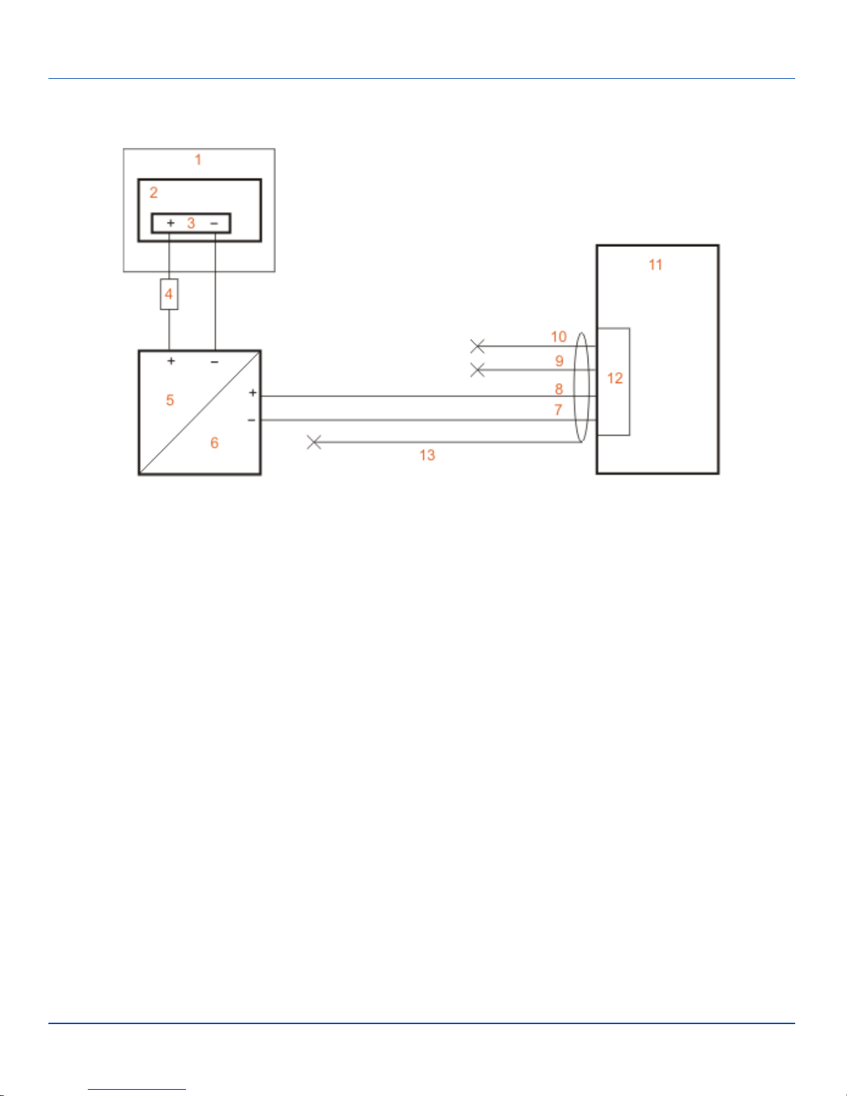
Connection without Screen Blanking
Connection without Screen Blanking
Power Cable Routing without Screen Blanking
1. Existing circuitry on vehicle
2. Forklift Battery
3. Main Switch
4. 10A slow fuse close to power source
5. Power input
6. Isolated DC power output
7. White
8. Brown
9. Yellow
10. Green
11. Vehicle mounted computer
12. Circular power connector
13. Supplied power cable (shielding to be trimmed)
E-EQ-VX8OGWW-G [ 16 ] Kärv User Guide
Page 21
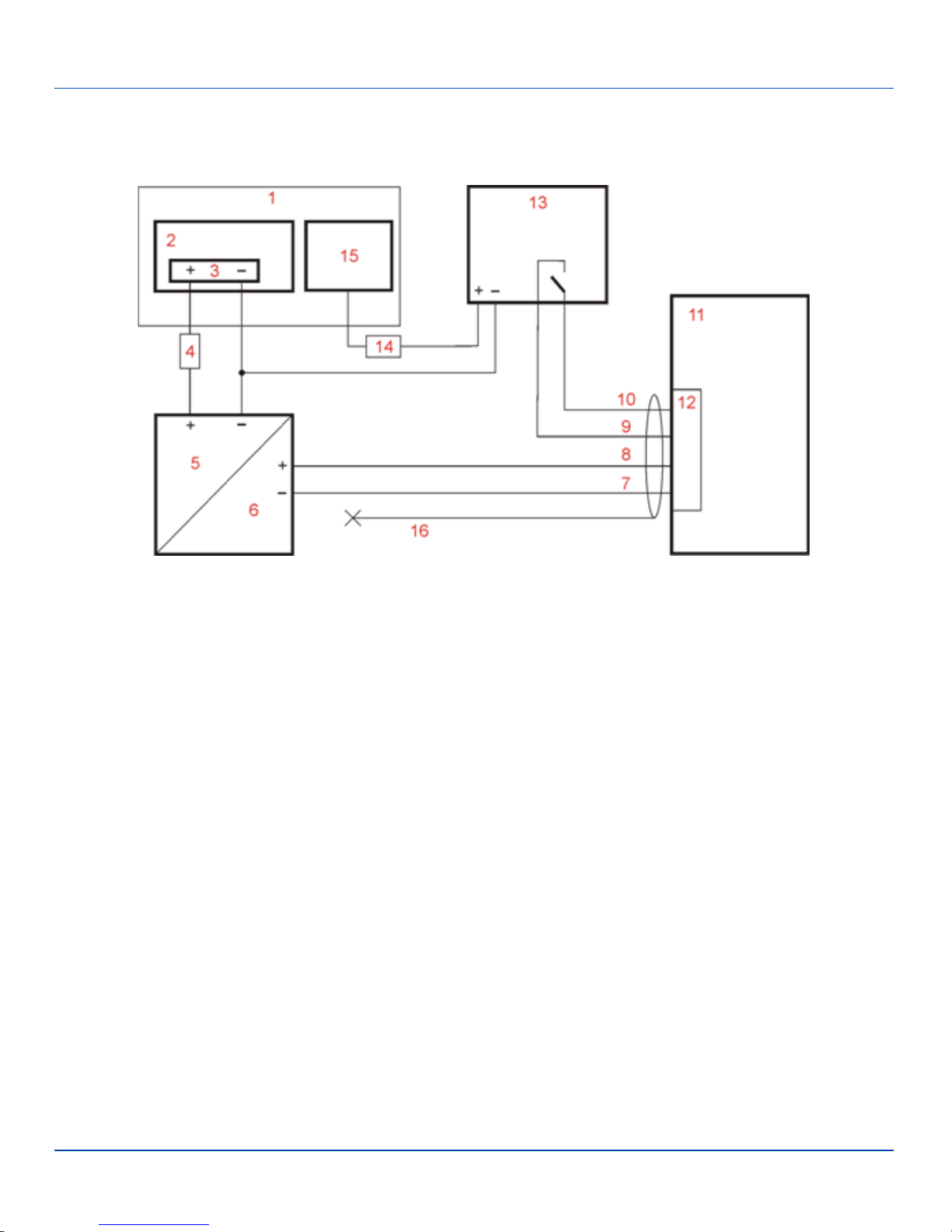
Connection with Screen Blanking Box
Connection with Screen Blanking Box
It is assumed that the motion sensing circuitry in the illustration below is powered by internal vehicle circuitry.
Power Cable Routing with Screen Blanking Box
1. Existing Circuitry on Vehicle
2. Forklift Battery
3. Main Switch
4. 10A slow fuse close to power source
5. Power Input
6. Isolated DC power output
7. White
8. Brown
9. Yellow
10. Green
11. Vehicle mounted computer
12. Circular power connector
13. Screen blanking box
14. 3A fuse
15. Motion circuitry - any 12-60/72VDC signal triggered by vehicle motion (see blanking box label for allowable range)
16. Supplied power cable (shielding to be trimmed)
E-EQ-VX8OGWW-G [ 17 ] Kärv User Guide
Page 22
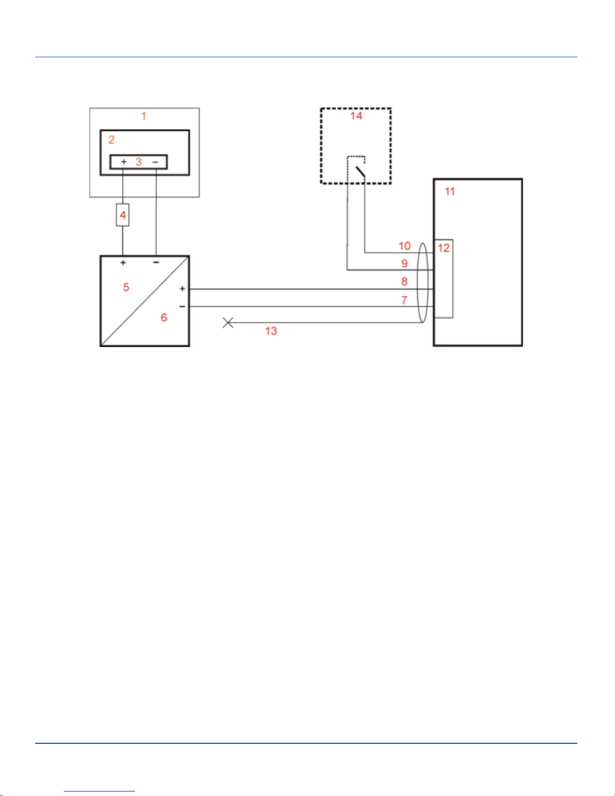
Connection with Relay/Mechanical Switch for Screen Blanking
Connection with Relay/Mechanical Switch for Screen Blanking
Power Cable Routing with Screen Blanking Switch/Relay
1. Existing Circuitry on Vehicle
2. Forklift Battery
3. Main Switch
4. 10A slow fuse close to power source
5. Power Input
6. Isolated DC power output
7. White
8. Brown
9. Yellow
10. Green
11. Vehicle mounted computer
12. Circular power connector
13. Supplied power cable (shielding to be trimmed)
14. Relay/switch that supplies a mechanical electrically conductive connection on vehicle motion.
E-EQ-VX8OGWW-G [ 18 ] Kärv User Guide
Page 23
Connect Multipurpose Cable
Connect Multipurpose Cable
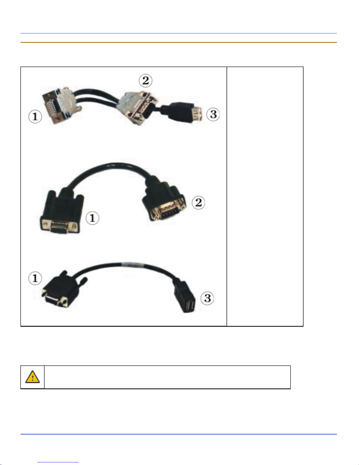
There are three optional dongle cables for use with the multipurpose port.
1. D15 Connector (to
Kärv)
2. D9 Serial Connector
(COM4)
3. USB Connector
These cables provide:
l A USBtype A plug
l A COM4 serial port connector
l Both a USB Type A port and a COM4 serial port
Pin 9 of COM4 provides +12V. Verify acceptable input voltages before connecting serial devices.
Configuration of COM port power is handled via the VMT Manager option in the Control Panel. For more information consult the
Kärv Reference Guide or the system administrator responsible for the configuration of the Kärv.
The multipurpose cable is attached to the port. The cable requires a nine-pin D-shell female connector for the Kärv.
E-EQ-VX8OGWW-G [ 19 ] Kärv User Guide
Page 24

Securing Port Lid
Connect Multipurpose Cable
1. Seat the cable connector firmly over the pins and turn the thumbscrews in a clockwise direction. Do not overtighten.
2. If a USB port is present, plug the desired device, such as a USB mouse or storage device, into the USB port. Refer to
the Windows help system and the documentation for your USB device for more information.USB devices may be
installed, removed or swapped without turning off the Kärv.
3. If a COM4 port is present, seat the serial device cable connector firmly over the pins and turn the thumbscrews in a
clockwise direction. Do not overtighten.
Securing Port Lid
The screws used for the port lid should be alternately tightened to provide proper dust and moist protection (IP65 requirement).
There are eight (8) Torx 20 screws securing the port lid.
Mounting the Port Lid
Fasten the cable tube in the vehicle, without putting strain on the tube. Now the Kärv is ready to be mounted in the vehicle.
E-EQ-VX8OGWW-G [ 20 ] Kärv User Guide
Page 25
Kärv Configuration Options
Kärv Configuration Options
Many configuration options are available via the Microsoft Windows Controlpanel. Refer to the Kärv Reference Guide or For
Help and Support on the Start menu for configuration details.
Date and Time
Use the Windows interface to set date, time and time zone. Tap the time displayed in the task bar or tap:
Start |Control Panel | Clock, Language and Region | Date and Time (Category view)
Start | Control Panel | Date and Time (Classic view)
Start | Control Panel | Date and Time (Classic view)
Start |Control Panel | Date, Time, Language and Regional Options | Change the Date and Time
(Category view)
Power Management
Use the Windows interface to set power management options.
Start |Control Panel | Hardware and Sound | Power Options (Category view)
Start | Control Panel | Power Options (Classic view)
Start | Control Panel | Power Options (Classic view), or tap
Start |Control Panel | Performance and Maintenance | Power Options (Category view)
Speaker Volume
Use the Windows interface to control speaker volume. Tap the speaker icon displayed in the task bar or tap:
Start |Control Panel | Hardware and Sound | Sound (Category view)
Start |Control Panel | Sound (Classic view)
Start | Control Panel | Sound and Audio Devices | Sounds (Classic view), or tap
Start |Control Panel | Sounds, Speech and Audio Devices | Adjust the System Volume (Category view)
Connect Bluetooth Devices
Use the Windows interface to manage Bluetooth devices.
Tap the Bluetooth iconon the Desktop.
Start | Control Panel | Bluetooth Devices (Classic view), or tap
Start | Control Panel | Printers and Other Hardware | Bluetooth Devices (Category view)
E-EQ-VX8OGWW-G [ 21 ] Kärv User Guide
Page 26
Restart/Shutdown
Restart/Shutdown
Use the Windows interface to restart or shut down the Kärv.
Start |Shut down right arrow list menu | Restart
Start |Shut down
Start | Shut down | Restart
Start |Shut down | Shut down
Soft Keyboard
The optional soft keyboard can be enabled and configured from the keyboard control panel in the MountFocus software.
Tap Start | Programs | MountFocus POS | Keyboard Control Panel
Calibrate Touchscreen
To calibrate the touchscreen, access the touchscreen software. Select:
l Tap Start | Programs | UPDD | Calibrate and touch the center of the cross displayed on screen and release. Repeat
as the cross is displayed in various locations. The utility closes automatically upon calibration completion.
E-EQ-VX8OGWW-G [ 22 ] Kärv User Guide
Page 27

Cleaning the Touchscreen and Scanner Aperture
Cleaning the Touchscreen and Scanner Aperture
Note: These instructions are for components made of glass. If there is a removable protective film sheet on the display,
remove the film sheet before cleaning the screen.
Keep fingers and rough or sharp objects away from the barcode reader scanning aperture and the mobile device touchscreen.
If the glass becomes soiled or smudged, clean only with a standard household cleaner such as Windex® without vinegar or
use Isopropyl Alcohol. Dampen the cloth with the cleaner and then wipe the surface.
Do not use paper towels or harsh-chemical-based cleaning fluids since they may result in damage to the glass surface. Use a
clean, damp, lint-free cloth.
Do not scrub optical surfaces. If possible, clean only those areas which are soiled. Lint and particulates can be removed with
clean, filtered canned air.
Apply the Touchscreen Protective Film
First, clean the touchscreen of fingerprints, lint particles, dust and smudges.
Remove the protective film from its container. Remove any protective backing from the film sheet by lifting the backing from a
corner of the film. Discard the backing.
Apply the film to the touchscreen starting at one side and smoothing it across the display. If air bubbles appear, raise the film
slightly and continue smoothing the film across the display until it covers the glass surface of the display. If dust, lint or
smudges are trapped between the protective film and the glass display, remove the protective film, clean the display and apply
the protective film again.
Contact your LXE representative about protective film packs designed specifically for your Kärv touchscreen.
Setup Terminal Emulation Parameters
Before you make a host connection, you will, at a minimum, need to know:
l the alias name or IP address (Host Address) and
l the port number (Telnet Port) of the host system to properly set up your host session.
1. Make sure the mobile client network settings are configured and functional. If you are connecting over wireless LAN
(802.11x), make sure your mobile client is communicating with the Access Point.
2. From Start | Program, run LXE RFTerm or tap the RFTerm icon on the desktop.
3. Select Session | Configure from the application menu and select the "host type" that you require. This will depend on
the type of host system that you are going to connect to; i.e. 3270 mainframe, AS/400 5250 server or VT host.
4. Enter the "Host Address" of the host system that you wish to connect to. This may either be a DNS name or an IP
address of the host system.
5. Update the telnet port number, if your host application is configured to listen on a specific port. If not, just use the
default telnet port.
6. Select OK.
7. Select Session | Connect from the application menu or tap the "Connect" button on the Tool Bar. Upon a successful
connection, you should see the host application screen displayed.
To change options such as Display, Colors, Cursor, Barcode, etc., please refer to these sections in the RFTerm Reference
Guide for complete descriptions of these and other features.
E-EQ-VX8OGWW-G [ 23 ] Kärv User Guide
Page 28
Regulatory Notices and Safety Information
Class A Digital Device
NOTICE
This device complies with FCC Rules, part 15. Operation is subject to the following two conditions:
1. This device may not cause harmful interference, and
2. This device must accept any interference received, including interference that may cause undesired operation.
NOTE: This equipment has been tested and found to comply with the limits for a Class A digital device, pursuant to Part 15 of
the FCC Rules. These limits are designed to provide reasonable protection against harmful interference when the equipment is
operated in a commercial environment. This equipment generates, uses, and can radiate radio frequency energy and, if not
installed and used in accordance with the instruction manual, may cause harmful interference to radio communications.
Operation of this equipment in a residential area is likely to cause harmful interference in which case the user will be required to
correct the interference at his own expense.
NOTICE
Changes or modifications made to this equipment not expressly approved by LXE, Inc., may void the FCC authorization to
operate this equipment.
Industry Canada
This Class A digital apparatus meets all requirements of the Canadian Interference Causing Equipment Regulations. Operation
is subject to the following two conditions: (1) this device may not cause harmful interference, and (2) this device must accept
any interference received, including interference that may cause undesired operation. Cet appareil numérique de la classe A
respecte toutes les exigences du Règlement sur le matériel brouilleur du Canada. Le présent appareil numérique n'émet pas de
bruits radioélectriques dépassant les limites applicables aux appareils numériques de Classe A prescrites dans le Réglement
sur le brouillage radioélectrique édits par le ministère des Communications du Canada.
EMC Directive Requirements:
This is a Class A product. In a domestic environment this product may cause radio interference in which case the user may be
required to take adequate measures.
Lithium Ion Battery
When disposing of the main battery, the following precautions should be observed: The battery should be disposed of properly.
The battery should not be disassembled or crushed. The battery should not be heated above 212°F (100°C) or incinerated.
Waste Electrical and Electronic Equipment (WEEE)
Important:
This symbol is placed on the product to remind users to dispose of Waste Electrical and Electronic Equipment
(WEEE) appropriately, per Directive 2002-96-EC. In most areas, this product can be recycled, reclaimed and reused when properly discarded. Do not discard labeled units with trash. For information about proper disposal,
Contact your LXE representative, or visit www lxe com.
Bluetooth and GSM technology are not available in Brazil. Bluetooth e tecnologia GSM não estão disponíveis no Brasil.
E-EQ-VX8OGWW-G [ 24 ] Kärv User Guide
Page 29
RF Safety Notice
RF Safety Notice
This device is intended to transmit RF energy. For protection against RF exposure to humans and in accordance with
FCC rules and Industry Canada rules, this transmitter should be installed such that a minimum separation distance of
at least 20 cm (7.8 in.) is maintained between the antenna and the general population. This device is not to be colocated with other transmitters.
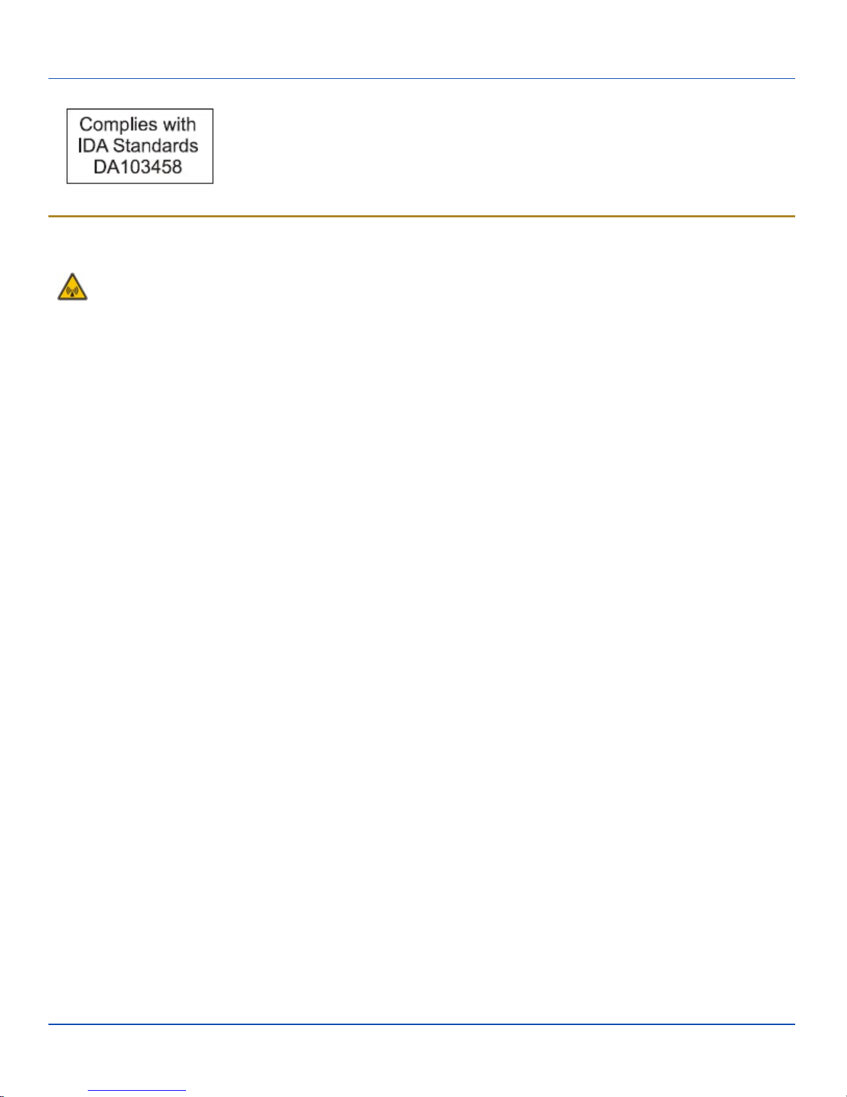
Republic of Singapore - LXE Dealer License Number DA103458 complies with IDA
Standards.
E-EQ-VX8OGWW-G [ 25 ] Kärv User Guide
Page 30
Lithium Battery Safety Statement
Lithium Battery Safety Statement
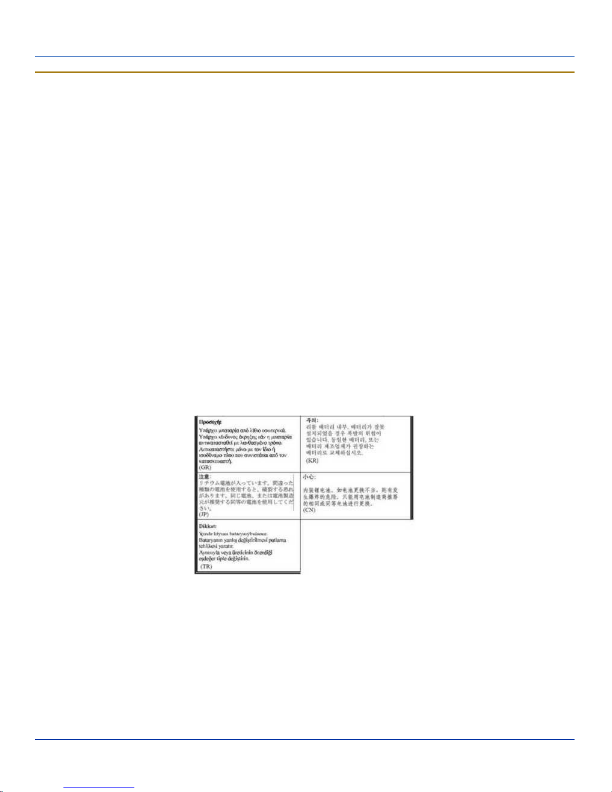
Caution: Lithium battery inside. Danger of explosion if battery is incorrectly replaced. Replace only with same or equivalent
type recommended by battery manufacturer. (US)
Attention: Contient une pile de lithium. Risque d’explosion dans le cas où la pile ne serait pas correctement remplacée.
Remplacer uniquement avec une pile semblable ou equivalente au type de pile recommandé par le fabricant. (FR)
Forsigtig: Indeholder lithiumbattterier. Risiko for eksplosion, hvis batteriet udskiftes forkert. Må kun udskiftes med samme eller
tilsvarende type, som anbefalet af fabikanten. (DK)
Varoitus: Tämä tuote käyttää laservaloa. Skannerissa on jokin seuraavista tarroista. Lue Huomio-kohta. (FI)
Vorsicht: Enthält Lithium-Batterie. Bei unsachgemäßem Ersatz besteht Explosionsgefahr. Nur durch gleichen oder vom
Hersteller empfohlenen Typ ersetzen. (DE)
Attenzione: Batteria al litio. Pericolo di esplosione qualora la batteria venga sostituita in maniera scorretta. Sostituire solo con
lo stesso tipo o equivalente consigliato per il fabbricante. (IT)
Atenção: Contém pilha de lítio. Há perigo de explosão no caso de uma substituição incorreta. Substitua somente pelo mesmo
tipo, ou equivalente, recomendado pelo fabricante.
(PT) Varning: Innehåller litiumbatteri. Fara för explosion om batteriet är felaktigt placerat eller av fel typ. Använd endast samma
eller motsvarande typ batterier rekommenderade av tillverkaren. (SE)
Advarsel: Innmontert Lithium batteri. Eksplosjonsfare ved feil montering av batteri. Benytt kun batteri anbefalt av produsent.
(NO)
Cuidado: Pila de litio adentro. Peligro de explosión si la pila se reemplaza incorrectamente. Reemplace solamente con el
mismo tipo o equivalente recomendado por el fabricante. (ES)
Oppassen: Bevat Lithium-batterij. Incorrrecte plaatsing van batterij kan leiden tot explosiegevaar. Alleen vervangen door
hetzelfde of door fabrikant aanbevolen gelijkwaardig type. (NL)
Legend: Danish – DK; English – US; Finnish – FI; French- - FR; German – DE; Greek – GR; Italian – IT; Norwegian – NO;
Portuguese – PT; Spanish – ES; Swedish – SE; Turkish – TR.
E-EQ-VX8OGWW-G [ 26 ] Kärv User Guide
Page 31

Vehicle Power Supply Connection Safety Statement
Vehicle Power Supply Connection Safety Statement
Vehicle Power Supply Connection: If the supply connection is made directly to the battery, a 10A slow-blow fuse should be
installed in the positive lead within 5 inches (12.7 cm.) of the battery positive (+) terminal. (US)
Raccordement de l’alimentation du véhicule Si l’alimentation est raccordée directement à la batterie, un fusible à action
retardée de 10A doit être installé sur le câble positif à moins de 12,7 cm de la borne positive (+) de la batterie. (FR)
EL forsyning af køretøjet. Er forsyningsforbindelsen direkte tilknyttet til batteriet og og tilsluttet til den positive part indenfor
12,7 cm (+ delen). vil der være en langsom tændelse af 10 ampere. (DK)
Kytkentä ajoneuvon virtalähteeseen Jos virtaa otetaan suoraan akusta, 10 ampeerin hidas sulake on asennettava
positiiviseen johtoon enintään 12 cm:n etäisyydelle akun positiivisesta (+) navasta. (FI)
Anschluss an Fahrzeugbatterie Bei direktem Anschluss an die Fahrzeugbatterie sollte eine träge 10A-Sicherung in die
positive Leitung zwischengeschaltet werden, und zwar nicht weiter als ca. 13 cm von der positiven (+) Batterieklemme
entfernt. (DE)
Σύνδεση Τροφοδοτικού Ισχύος Οχήματος Αν η σύνδεση του τροφοδοτικού γίνει κατευθείαν στη μπαταρία, μια ασφάλεια
βραδείας τήξης των 10A θα πρέπει να τοποθετηθεί στο θετικό καλώδιο εντός 5 ιντσών (12,7 εκ.) του θετικού (+) ακροδέκτη
της μπαταρίας. (GR)
Collegamento dell’alimentazione del veicolo Se il collegamento dell’alimentazione viene stabilito direttamente con la batteria, è
necessario installare un fusibile ad azione lenta da 10A nel conduttore positivo a meno di 5 in. (12,7 cm) dal terminale positivo
(+) della batteria. (IT)
Tilkople strømforsyningen til kjøretøyet Hvis strømforsyningen koples direkte til batteriet, skal det installeres en 10A treg
sikring i den positive ledningen innen 12,7 cm fra plusspolen (+) på batteriet. (NO)
Ligação do fornecimento de corrente do veículo Se a ligação de fornecimento de corrente for ligada directamente à bateria,
deve instalar-se um fusível de 10A no terminal positivo, a 12,7 cm. do terminal positivo (+) da bateria. (PT)
Conexión de suministro eléctrico para el vehículo Si el suministro eléctrico se proporciona directamente a la batería, se debe
instalar un fusible de retardo de 10A en el conductor positivo, como máximo a 12,7 cm (5 pulgadas) del terminal positivo (+).
(ES)
Fordonets strömförsörjningskoppling Om strömkopplingen görs direkt till batteriet, måste en 10A-säkring installeras i den
positivt laddade ledningen inom 12.7 cm från batteriets pluspol (+). (SE)
Taşıt Güç Kaynağı Bağlantısı Kaynak bağlantısı doğrudan aküye yapılırsa, pozitif bağlantı kablosu üzerinde akünün pozitif (+)
kutbuna 12.7 cm mesafede 10A’lık yavaş atan bir sigorta monte edilmelidir. (TR)
Legend: Danish – DK; English – US; Finnish – FI; French- - FR; German – DE; Greek – GR; Italian – IT; Norwegian – NO;
Portuguese – PT; Spanish – ES; Swedish – SE; Turkish – TR.
E-EQ-VX8OGWW-G [ 27 ] Kärv User Guide
Page 32
Revision History
Revision History
Revision / Date Location / Change
G / Jul 2011
F / Apr 2011
E / Jul 2010
D / Mar 2010 Connecting Vehicle Power / Revised instructions for new DC to DC power supply options.
C / Jan 2010 Components / Added Component pages.
B / Dec 2009 Cover page and contents / Formatted for browser delivery and applied Marketing color scheme.
A / Mar 2009 Initial Release
Entire guide / Added Windows 7 Professional operating system instruction as needed. Added
Singapore Dealer segment to Regulatory Notices.
1. Title / Changed title to Kärv User Guide.
2. Connecting Vehicle Power / Specified 10 amp fuse.
3. Connecting Vehicle Power / Revised screen blanking connections.
1. Connect Ethernet Cable / Add shielded cable note.
2. Connect Serial Barcode Scanner / Revised shielded cable note.
E-EQ-VX8OGWW-G [ 28 ] Kärv User Guide
Page 33

Index
A
AC Power Supply 12
Apply the Touchscreen Protective Film 23
P
port lid, removing 8
port lid, securing 20
Power key 1
Power Management 21
Protective film for touchscreen 23
B
barcode scanner 11
C
Calibrate 22
Class A Digital Device 24
Components 2
Configuration Options 21
Connect Bluetooth Devices 21
Connect Ethernet Cable 10
Connect External Headset 12
Connect Keyboard 8
Connect USB Devices 10
Connecting Cables 8
Connecting Vehicle Power 12
D
Date and Time 21
G
Good Scan LED 11
R
Restart 22
Revision History 28
RF Safety Notice 25
S
Set Up A New Device 1
Setup Terminal Emulation Parameters 23
Shutdown 22
Soft Keyboard 22
Software Setup 1
Speaker Volume 21
Stylus
how to use 5
T
Touchscreen
and the stylus 5
Touchscreen protective film 23
Trigger 11
H
Hardware Setup 1
L
Laser Aperture 11
M
Multipurpose Cable 19
E-EQ-VX8OGWW-G [ 29 ] Kärv User Guide
W
WEEE 24
 Loading...