

Page 1
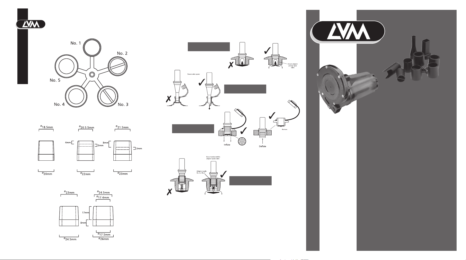
Nozzle Selection
Valve Assemblies
Typical valve assemblies showing the correct use of the adaptor.
Thick section rubber valve
Front Page
Plastic PVC valve
No. 1 No. 2 No. 3
No. 4 No. 5
Thin section rubber valve
This type of valve is opened
by the air ow of the High
Speed Inator
Sprung load valve
LVM 110 Hi-Speed Inator/Deator
Designed in the UK
Made in China
Page 2
Hi-Speed Inator/Deator
Features
Rapid ination and deation of all inatables.
Inates a four man dinghy in 1 to 2 minutes.
Deates, removing every last ounce of air for easy storage.
Adjustable nozzles for all inatables and valve types.
Light weight and easy to use.
Easier and faster than manual pumps.
Temperature sensitive air release valve protects from overheating and
over inating.
Robust long life construction.
Operating Instructions
If these simple instructions are followed then your Hi-Speed Inator / Deator will take the
hassle out of inating and deating your dinghy for many years to come.
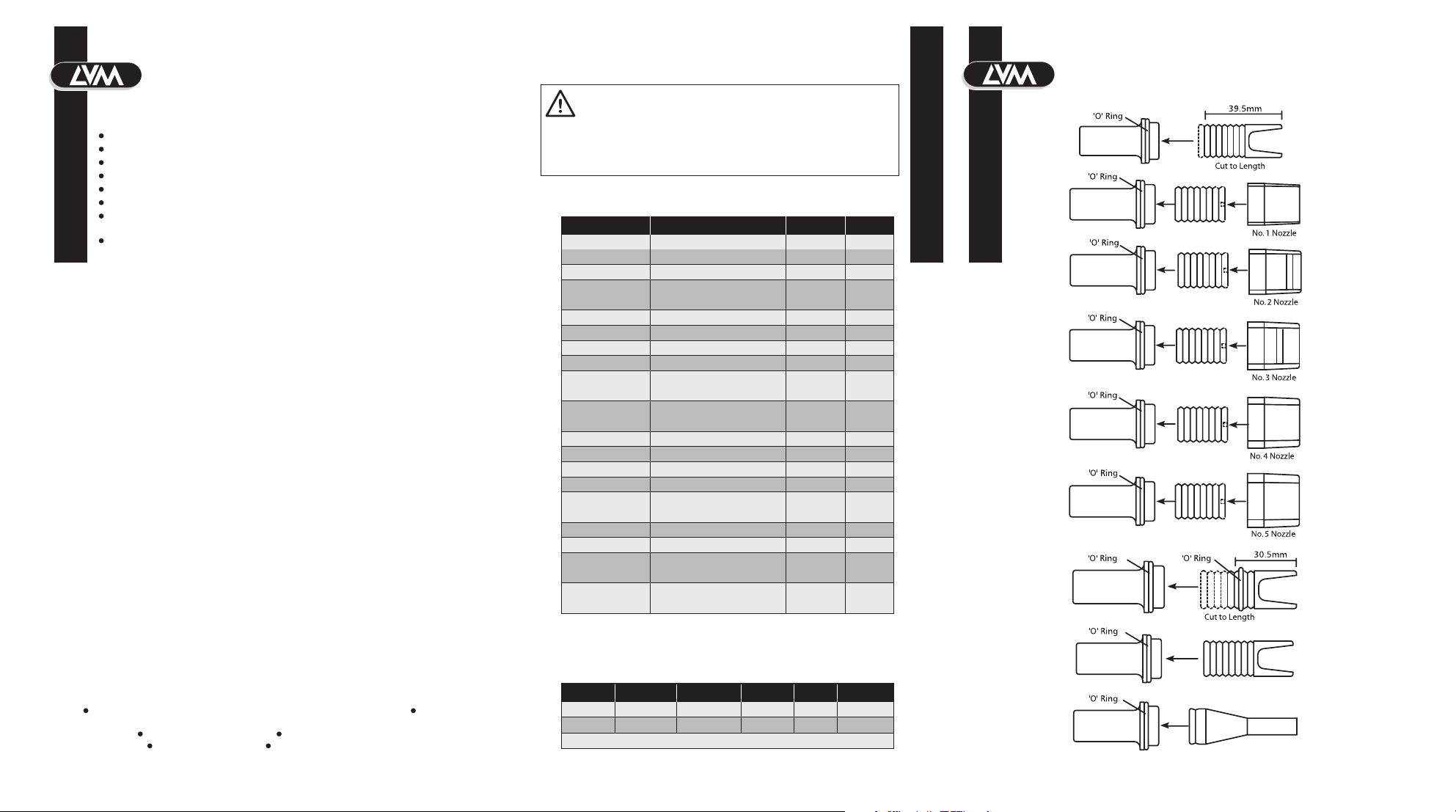
1. Make sure the correct adaptor is selected to suit your valve (see diagrams showing typical
valve assemblies). Failure to use the correct adaptor will reduce performance and create
back pressure which causes unwanted heat.
2. Insert adaptor into inate / deate port of the Hi-Speed Inator.
3. Ensure your battery is in good condition and has a sucient capacity of 45 AH minimum.
4. Uncoil cable, connect the red (+) battery clip to the positive terminal and the black
(-) battery clip to the negative terminal.
5. Fully engage the adaptor into the dinghy valve and completely depress the switch.
Safety
If the Inator is connected to a circuit using connections other than the battery clips
supplied the connecting fuses should be rated at 25 amps at 12 volts DC. Cigar lighter
sockets are NOT suitable.
Do not try to over-inate the dinghy. The Hi-Speed Inator will give between 0.18 and 0.21
bar (2.6 and 3.0 p.s.i.), which is suitable in most instances. If extra pressure is required, top
up with a
manual pump.
When maximum ination / deation is reached you will note a change of tone. If the unit is
left running after the tone change no more pressure will be achieved and the air retained in
the pump chamber will heat rapidly. The temperature sensitive air release valve will open,
releasing the hot air and protecting the unit from over heating. However, it will not protect
the unit indenitely and the unit should be switched o immediately the change of tone is
heard and the release valve starts to vent air. On cooling the air release valve will reset.
The inator should not be placed bottom down on a surface when operating as the air
release valve will not function.
The lead can be extended to 20 ft (6 m) without signicantly aecting performance.
The minimal cross sectional area of the extending cable should be 10 AWG copper wire
2
(2.5mm
). For longer extensions the cable should be 8 AWG copper wire (4.0mm2)
minimum.
Store away from excessive heat and direct sunlight to avoid external damage. If the
pump fails to perform, check for blockages, air leaks and correct electrical and adaptor
connections.
operation only.
Unwrap cables fully before use. Do NOT secure in ‘ON’ position - hand
Do NOT immerse in water.
W ARNING
When powering this product from a car or a boat battery do not switch
‘on’ and run the engine. The unit is designed to operate at 12 to 12.7
volts. If the engine is switched on the voltage could rise to 14 -15 volts,
which will seriously damage the Inator and the warranty will be
disclaimed. The leads could also entangle in the fan belt and cause
personal and property damage.
Selecting the correct adaptor
F
Manufacturer Valve Type Diagram Nozzle
A7A)epyt dlo yrev( novA
Bombard Small valve 17.5mm I.D. (inate) H
Large recessed D 3
Compass Large Recessed valve D 3
F 3DruoF ecro
Deate B 1
OMC Express Old type valve A
New type valve(recessed) D 3
ArevliskciuQ
T 2C 7B ro 7Aodanro
V 2Ctnaila
Zodiac Small valve 17.5mm I.D. (Inate) A
and Airbeds etc.
Note: When deating dinghies with A7 or B7 valves the centre section of the valve can
be locked in the open position by pushing fully in and turning anti-clockwise.
Specications
Model Airow Pressure Amps Volts Weight
LVM110 20 ft/min32.6 psi/min 25 max. 12 1.6lbs
Cable length 3 metres (10ft). Fitted with battery clips.
B7 or C7 C 2
Large recessed D 3
Aevlav epyt dlo 5ArekniT
GhtineZ
JselbatalfnI CVP llamS
Valve Assemblies
Diagram A
Diagram B
2C7A)epyt dlo( novA
2C7B)epyt wen( novA
2C7B ro 7AatleD
2C7BrebmuH
5FetalfnInoxxaM
2C 7B ro 7AtfarcbiR
2C 7B ro 7AhcetbiR
smrg057nim/rab 81.0mpl 055
Diagram C
Diagram D
Diagram E
Diagram F
Diagram G
Diagram H
Diagram J
 Loading...