

PULITO PERSONALIZZATO • CUSTOMIZED CLEANING • NETTOYAGE PERSONNALISÉ •
KUNDENORIENTIERTE REINIGUNG • LIMPIEZA PERSONALIZADA
ATTENZIONE!
NON USARE L’APPARECCHIO SENZA AVER LETTO LE ISTRUZIONI PER L’USO
ATTENTION! DO NOT USE THE MACHINE BEFORE READING THE INSTRUCTIONS FOR USE
ATTENTION! NE PAS UTILISER LA MACHINE SANS LIRE LES INSTRUCTIONS POUR L’EMPLOI
ACHTUNG! DIE MASCHINENICHT GEBRAUCHEN, OHNE VORHER DIE ANLEITUNGEN GELESEN ZU HABEN
ATENCIÓN! LA MÁQUINA NO DEBE SER UTILIZADA SIN HABER LEÍDO LAS INSTRUCCIONES PARA EL EMPLEO
USO E MANUTENZIONE
USE AND MAINTENANCE
EMPLOI ET ENTRETIEN
BEDIENUNG UND
WARTUNGSANLEITUNG
USO Y MANTENIMENTO
Magna 85-100-85S-100S
CODICE T5114002 GB 01/2005
LVC UK
Unit 1 Brookside, Colne Way Industrial Estate
Watford , Hertfordshire, WD24 7QJ
Tel: 01923 445 550
info@lvcuk.com
www.lvcuk.com

2
SUMMARY
SUMMARY .............................................................................................................................................................................2
ON DELIVERY OF THE MACHINE.............................................................................................................................................3
INTRODUCTION......................................................................................................................................................................3
SOUND POWER LEVEL LABEL................................................................................................................................................................... 3
TECHNICAL DESCRIPTION.......................................................................................................................................................4
TECHNICAL DESCRIPTION............................................................................................................................................4
SYMBOLOGY USED ON THE MACHINE....................................................................................................................................5
SYMBOLOGY USED ON THE MACHINE.................................................................................................................................... 6
MACHINE PREPARATION........................................................................................................................................................ 8
1. HANDLING THE PACKED MACHINE...................................................................................................................................................... 8
2.HOW TO UNPACK THE MACHINE.......................................................................................................................................................... 8
3. INSTALLATION OF THE BATTERIES INTO THE MACHINE.......................................................................................................................... 9
4. CONNECTION OF THE BATTERY CONNECTOR........................................................................................................................................ 9
5. CONNECTION OF THE BATTERY CHARGER............................................................................................................................................10
6. RECHARGING THE BATTERIES.............................................................................................................................................................10
7. BATTERY CHARGE LEVEL INDICATOR..................................................................................................................................................10
8. SQUEEGEE.........................................................................................................................................................................................11
9. ASSEMBLY; SIDE BARS 85S-100S......................................................................................................................................................11
10. ADJUSTMENT; SQEEGEE HEIGHT SUPPORT........................................................................................................................................12
11. BRUSHES ASSEMBLY; MAGNA 85-100..............................................................................................................................................13
12.SOLUTION WATER.............................................................................................................................................................................14
13. RECOVERY TANK ..............................................................................................................................................................................14
GENERAL RULES OF SECURITY.............................................................................................................................................. 15
PERFORMANCE ....................................................................................................................................................................16
CHECK MOTOR BRUSHES......................................................................................................................................................................18
BRUSH PRESSURE.................................................................................................................................................................................18
TRACTION.............................................................................................................................................................................................18
SQUEEGEE; AUTOMATIC – MANUAL .......................................................................................................................................................19
BRAKES................................................................................................................................................................................................19
BRAKES................................................................................................................................................................................................19
HORN...................................................................................................................................................................................................19
BLINKING AND WORKING LIGHTS..........................................................................................................................................................20
ON COMPLETION OF WORK.................................................................................................................................................. 21
ON COMPLETION OF WORK.................................................................................................................................................. 22
DAILY MAINTENANCE ......................................................................................................................................................... 23
CLEANING OF THE RECOVERY TANK........................................................................................................................................................23
CLEANING THE SQUEEGEE......................................................................................................................................................................23
REPLACEMENT OF THE SQUEEGEE RUBBER .............................................................................................................................................24
REMOVAL OF BRUSHES; MAGNA 85/100.......................................................................................................................................24
REMOVAL OF THE CYLINDRICAL BRUSHES; MAGNA 85S-100S................................................................................................25
SOLUTION TANK AND FILTER CLEANING..................................................................................................................................................26
DIRT HOPPER CLEANING........................................................................................................................................................................27
DAILY MAINTENANCE...........................................................................................................................................................28
ADJUSTMENT; SPLASH GUARD BRUSHES BASE MAGNA 85......................................................................................................................28
ADJUSTMENT; SPLASH GUARD BRUSHES BASE MAGNA 100....................................................................................................................28
ADJUSTMENT; SIDE BARS MAGNA 85/S 100/S.........................................................................................................................................29
CLEANING OF THE SUCTION HOSE.........................................................................................................................................................29
CLEANING SUCTION MOTOR FILTER.......................................................................................................................................................29
TROUBLE SHOOTING GUIDE.................................................................................................................................................. 30
INSUFFICIENT WATER ONTO THE BRUSHES..............................................................................................................................................30
THE MACHINE DOES NOT CLEAN SATISFACTORILY...................................................................................................................................30
THE SQUEEGEE DOES NOT DRY PERFECTLY..............................................................................................................................................30
THE SUCTION MOTOR DOES NOT FUNCTION............................................................................................................................................31
THE MACHINE DOES NOT START.............................................................................................................................................................31
EXCESSIVE FOAM PRODUCTION..............................................................................................................................................................31
CHOICE AND USE OF BRUSHES.............................................................................................................................................32
3
On delivery of the machine
When the machine is delivered to the customer, an
immediate check must be performed to ensure all the
material mentioned in the shipping documents have
been received and moreover to find out that the
machine has not suffered damage during transportation.
If damage has occurred, get the shipping agent to verify
immediately the amount and nature of the damage
suffered and at the same time inform our claim
department. It is only by prompt action of this type that
compensation for damage may be successfully claimed.
Introduction
This is a floor cleaning machine which, using the
mechanical abrasive action of two cylindrical brushes
and the chemical action of a water-detergent solution,
is able to clean any type of hard floor, picking up during
its forward movement, the removed dirt / detergent
solution from the floor. The machine must be used only
for such purpose. We would impress upon you that any
machine will function efficiently and operate
successfully, only if used correctly and maintained in
fully efficient working order. We therefore suggest that
you read this instruction booklet carefully and re-read it
whenever difficulties arise in the course of machine use.
Our service department is at your disposal for such
advice and servicing as may prove necessary.
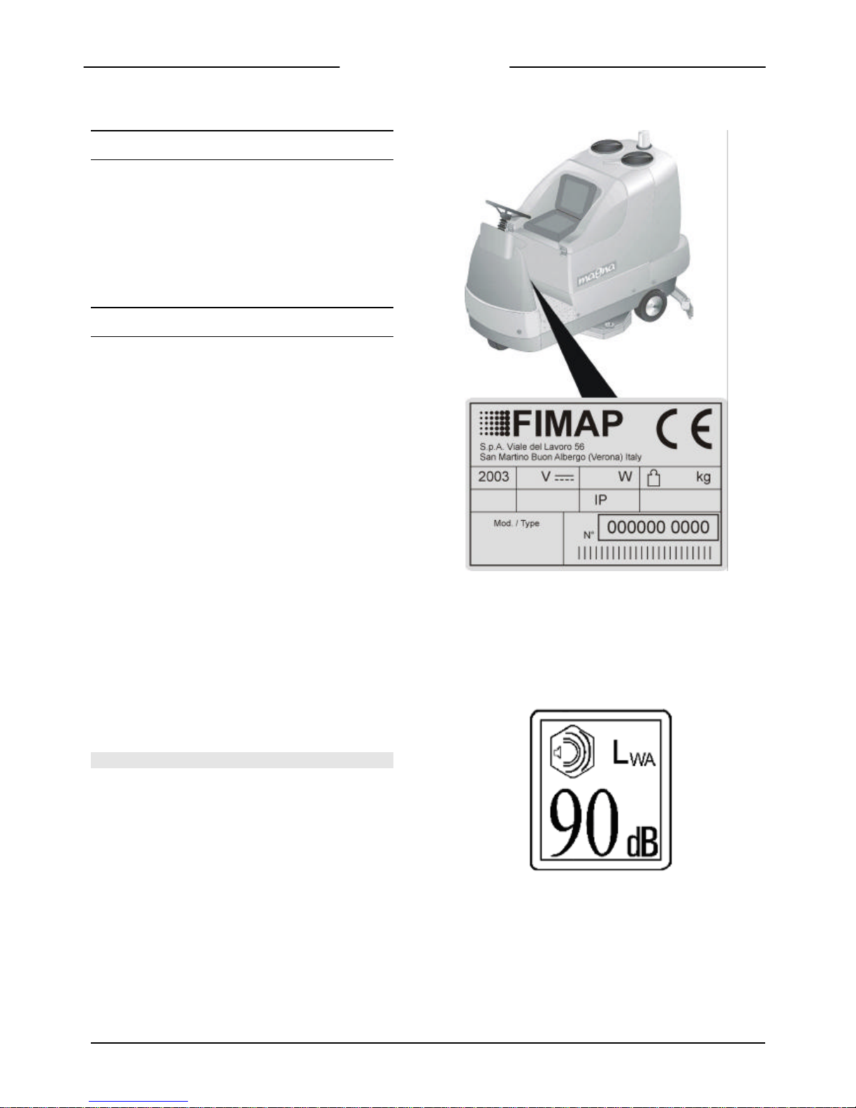
SOUND POWER LEVEL LABEL

4
TECHNICAL DESCRIPTION
TECHNICAL DESCRIPTION Magna 85 Magna 100 Magna 85S Magna 100S
Cleaning width mm 850 1000 850 1000
Base side movement mm 150 150
Squeegee width mm 1120 1279 1120 1279
Working capacity (at max. speed) mq/h 5500 6500 5500 6500
Water consumption g/m2 90 90 70 70
Brushes (No,)
∅ mm 430 (x2) 510 (x2)
Cylindrical brushes (No,) ∅ xmm 210x850 (2) 210x1000 (2)
Brushes rpm giri/min 180 180 700 700
Brushes pressure kg 130max 150max 63 60
Max. specific pressure g/cm2 54 52 70 68
Brushes motor V 36 36 36 36
Brushes motor W 1500 2000 2x1000 2x1000
Traction motor V 36 36 36 36
Traction motor W 1100 1100 1100 1100
Traction wheel ∅ mm 300 300 300 300
Movement speed km/h 0÷6.5 0÷6.5 0÷6.5 0÷6.5
Max. gradient under full load 10% 10% 10% 10%
Suction motor V 36 36 36 36
Suction motor (No,) W 670(x2) 670(x2) 670 (x2) 670 (x2)
Suction vacuum mbar 190 190 190 190
Rear wheels ∅ mm 300x90 300x90 300x90 300x90
Solution tank l 200 200 200 200
Recovery tank l 215 215 215 215
Steering diameter mm 2500 2500 2500 2500
Machine length mm 1960 1960 1960 1960
Machine height mm 1500 1500 1500 1500
Machine width mm 870 1120 860 1115
Batteries (No,) V/Ah 36/360max (1) 36/360max (1) 36/360max (1) 36/360max (1)
Batteries weight kg 370 max 370 max 370 max 370 max
Machine weight (empty and without batteries) kg 490 515 475 500
Noise level (in conformity with IEC 704/1) dB (A) 69 69 69 69
Hand vibration level m/s² 2,1 2,1 1,6 1,6
Body vibration level m/s² 1,1 1,1 0,3 0,3
5
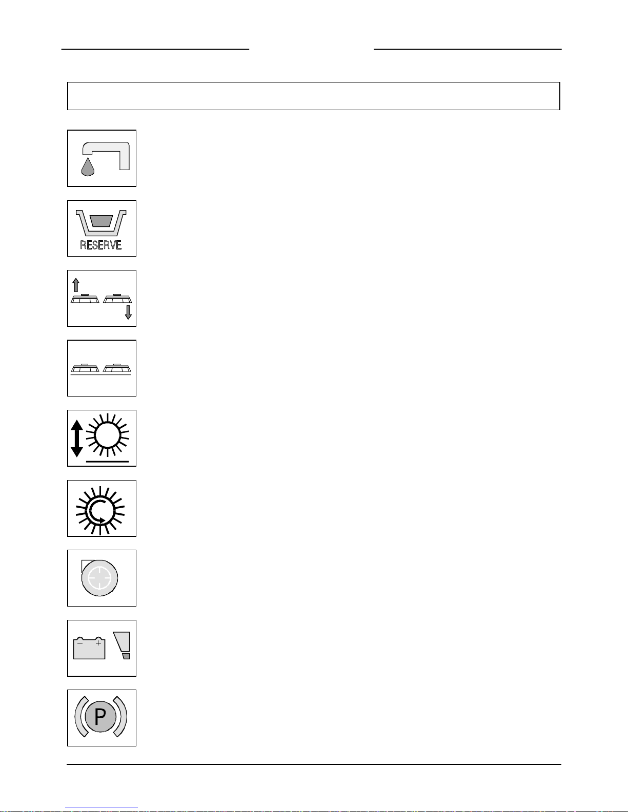
SYMBOLOGY USED ON THE MACHINE
Symbol denoting solenoid valve open
It is used to indicate the switch of the solenoid valve
Symbol denoting solution tank empty
Symbol denoting up - down of the brushes base Magna 85/100.
It is used to indicate the signal lamp of the brushes actuator when operating.
Symbol denoting brush Magna 85/100.
It is used to indicate the brushes motor switch
Symbol denoting ‘up-down’ of the cylindrical main brushes on Magna 85S/100S
It is used to indicate the light showing movement of the brush actuator
Symbol denoting cylindrical brushes of Magna 85S/100S
It is used to indicate the brush motor switch
Symbol denoting suction motor
It is used to indicate the suction motor switch
Symbol denoting charge level of batteries
Symbol denoting brake
It is used to indicate the signal lamp of the activated hand brake
It is used to indicate oil low-level warning in the working brake system
It is used on the top of the emergency brake lever
6
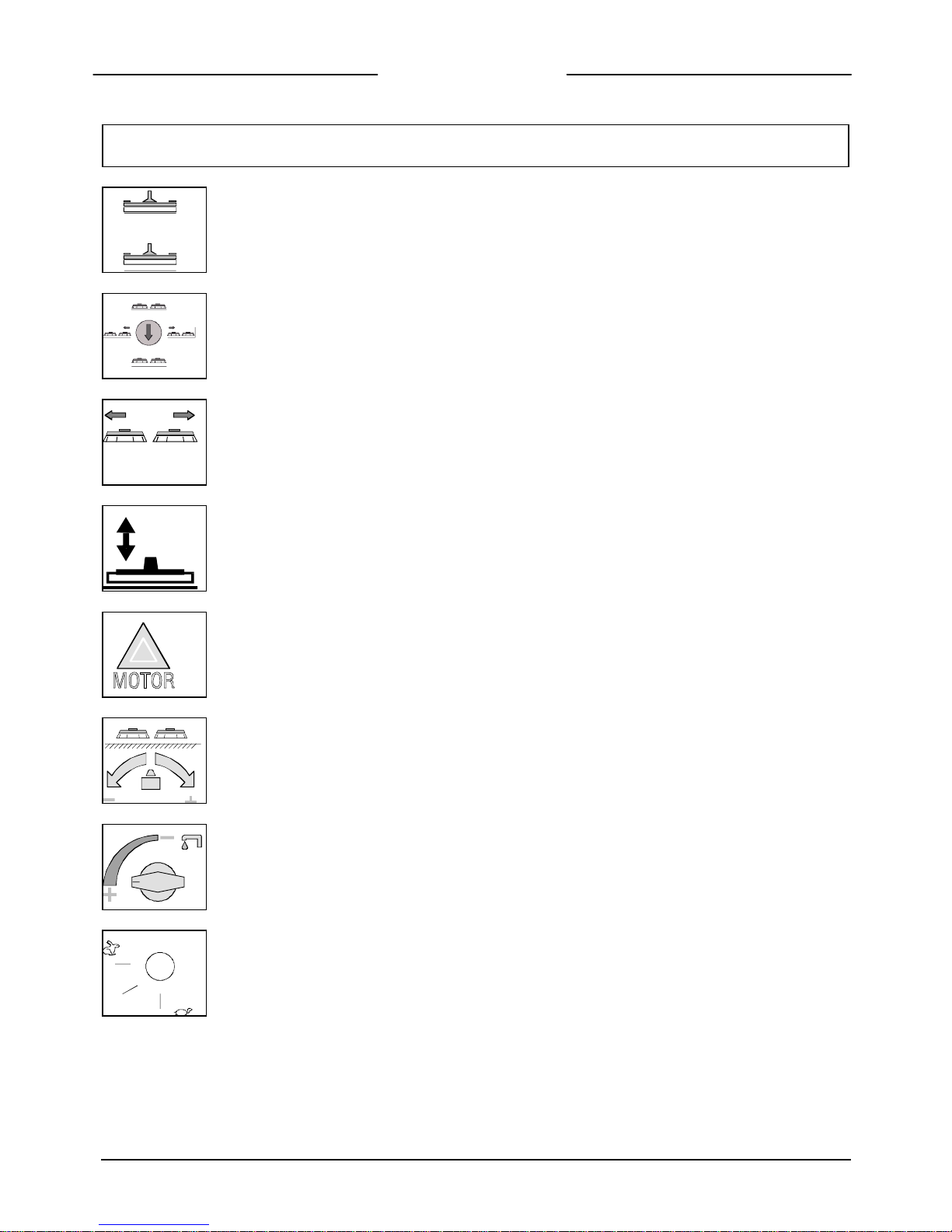
SYMBOLOGY USED ON THE MACHINE
Symbol denoting up – down of the squeegee
It is used to indicate the commutator for squeegee lifting
Symbol denoting manipulator brushes Magna 85/100.
It is used on the instrument board to indicate the manipulator of the brushes base. Making side
movements with the manipulator, they correspond to side movements of the brushes base.
Longitudinal movements correspond to vertical movements of the brushes base.
Symbol denoting stop base side movement Magna 85/100.
The green signal lamp comes on when the brushes base is moved all to the left side.
Symbol denoting squeegee fully down (green signal lamp).
Symbol denoting high running amps of the brushes motor (red signal lamp)
The signal lamp comes on when the brushes motor is over-loaded
Symbol denoting pressure carried on the brushes Magna 85/100
Symbol denoting water supply regulation cock
3
2
Symbol denoting speed selector, forwards and reverse
7
SYMBOLOGY USED ON THE MACHINE
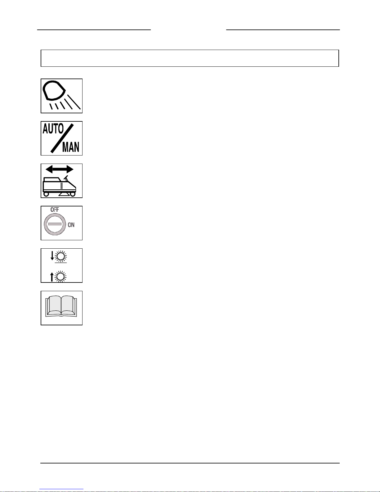
Symbol denoting the switches ‘blinking’
Symbol denoting the selector working mode; automatic or manual
Symbol of the ‘Travel drive’ joy-stick.
Depending on its position the machine moves in a Forward or Reverse direction
Symbol denoting the ‘on/off’ switch
Symbol of the ‘Brush’ joy
-
stick of Magna 85S/100S
It is used on the instrument panel to indicate the ‘joy-stick’ for brush movement.
Pushing the lever forwards lowers the brushes, pulling it backwards raises them
Symbol open book
In order to point out that the operator should read the handbook before using the machine
8
MACHINE PREPARATION
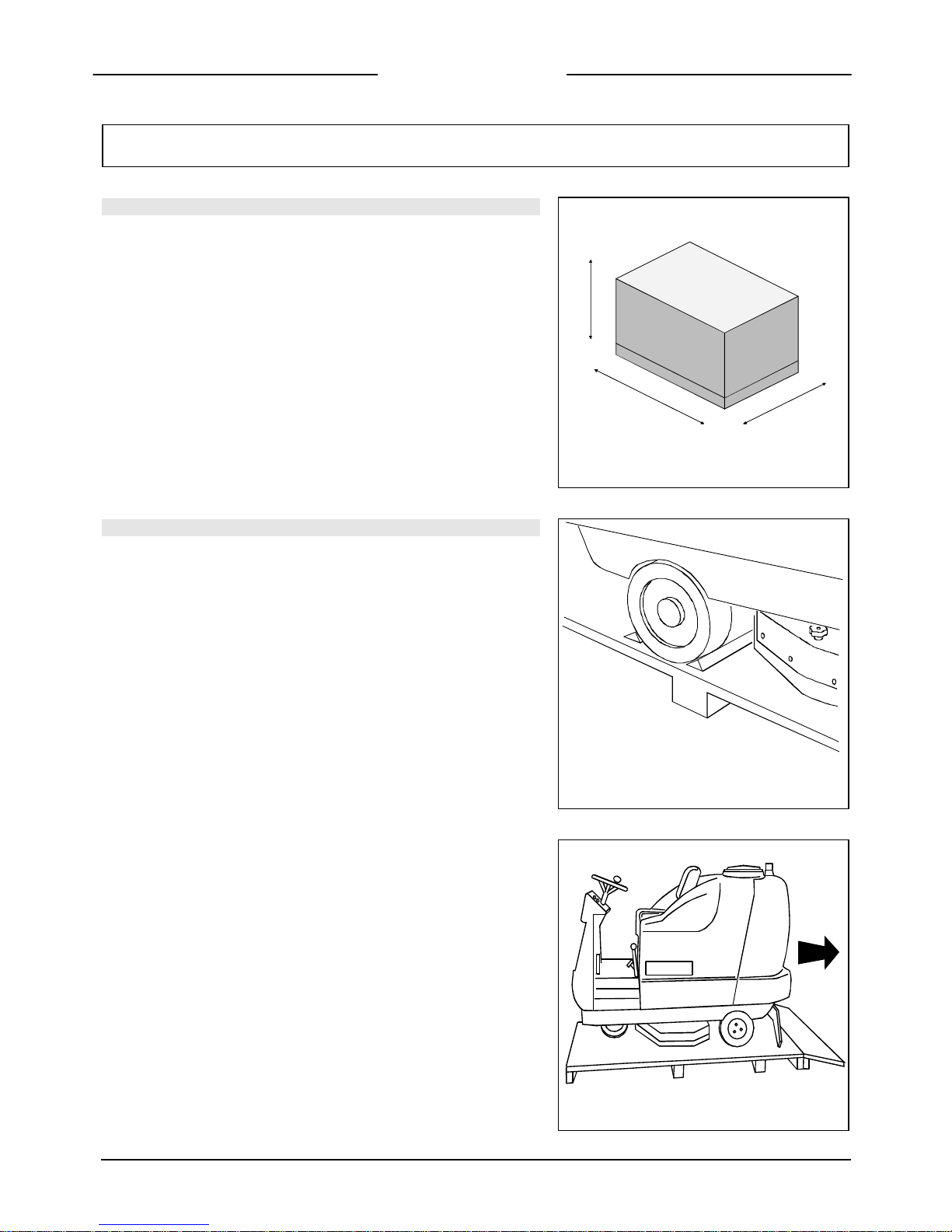
1. HANDLING THE PACKED MACHINE
Figure 1
The machine is packed in a special package provided on a pallet for
handling with fork trucks. The packages cannot be placed on top of each
other.
The total weight is 555 kg for the Magna 85, 580 kg for the Magna 100,
590 kg for the Magna 85/S and 619 kg for the Magna 100/S
The overall dimensions are:
A : 1620 mm
B : 1300 mm
C : 2010 mm
A
C
B
2. HOW TO UNPACK THE MACHINE
Figure 2
1. Remove the outer packaging
2. The machine is fixed on the pallet with wooden wedges which block
the wheels
3. Remove these wedges
Figure 3
4. Use a ramp to get the machine down from the pallet, pushing it in
reverse motion. Avoid violent blows to the base.
5. Keep the pallet in case of further transport needs
9
MACHINE PREPARATION
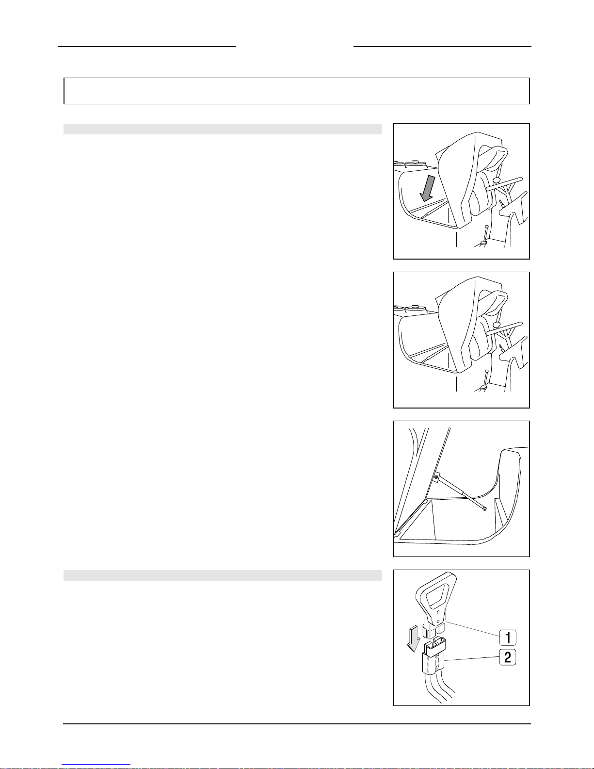
3. INSTALLATION OF THE BATTERIES INTO THE MACHINE
Figure 4
The batteries are fitted in the appropriate compartment under the seat and must be
handled by using lifting equipment suitable both for the weight and for the coupler
system. They must moreover satisfy the requirements quoted in the Specification CEI
21-5.
For maintenance and daily recharging of the batteries, it is necessary to follow strictly
all the indstructions given by the manufacturer or from his dealer. Specialized staff
must carry out all the installation and maintenance operations.
Figure 5
In order to insert the batteries it is necessary to:
1. Lift the seat support
2. Extract the prop from its slot
3. Lean the seat on the steering wheel
4. Insert the batteries
Figure 6
5. Lower the base support of the seat being careful to have at first refastened the tie.
4. CONNECTION OF THE BATTERY CONNECTOR
Figure 7
The battery connector (1) is placed in the left lower part of the operators seat and
must be connected to the connector (2) of the machine.
MACHINE PREPARATION
5. CONNECTION OF THE BATTERY CHARGER
The connector is placed in the left lower part of the operator seat. The
upper part (1), which is connected to the batteries, is the one which has to
be inserted to the connector (2) fixed to the cables of the battery charger.
The coupling connector of the battery charger is delivered in the bag
(together with this instruction booklet ) and must be assembled on the
battery charger cables following the provided instructions (see
instructions booklet for the battery charger).
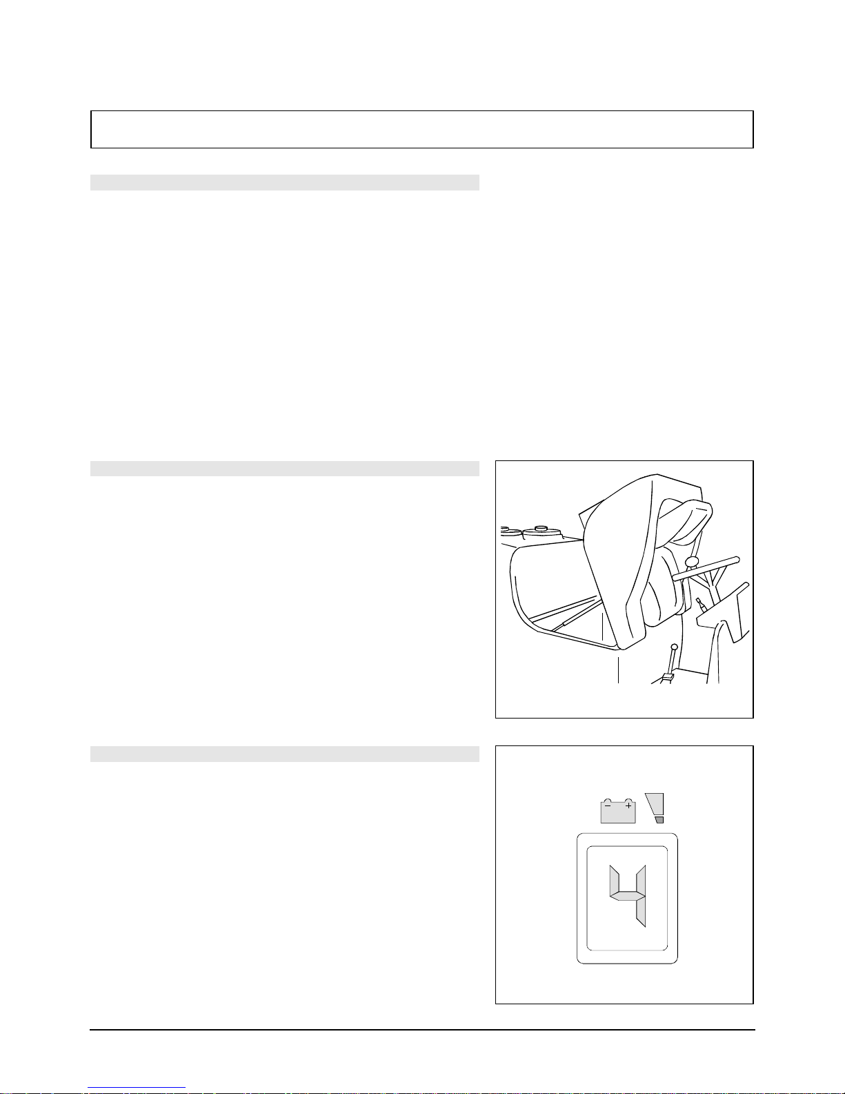
6. RECHARGING THE BATTERIES
Figure 8
To ensure no permanent damage to the battery it is essential to avoid
complete discharge by arranging to recharge as soon as the blinking
signal indicating the discharged batteries switches on.
NOTE: Never leave the batteries completely discharged, even if the
machine is not being used.
When recharging the batteries, keep the base support of the seat
lifted. Every 20 recharging operations, check the level of the electrolyte
and, if necessary, top up with distilled water.
7. BATTERY CHARGE LEVEL INDICATOR
Figure 9
The digital battery signal has 4 fixed positions and a blinking one. The
numbers which appear in the display show the approximate charge level.
4 = maximum charge, 3 = ¾ charge, 2 = ½ charge, 1 = ¼ charge,
0 = discharged batteries (blinking)
ATTENTION: A few seconds after the appearance of the blinking “0” the
brush motor automatically switches off. With the rest of the charge it is
possible to finish any drying operation before starting the recharge.
11
MACHINE PREPARATION
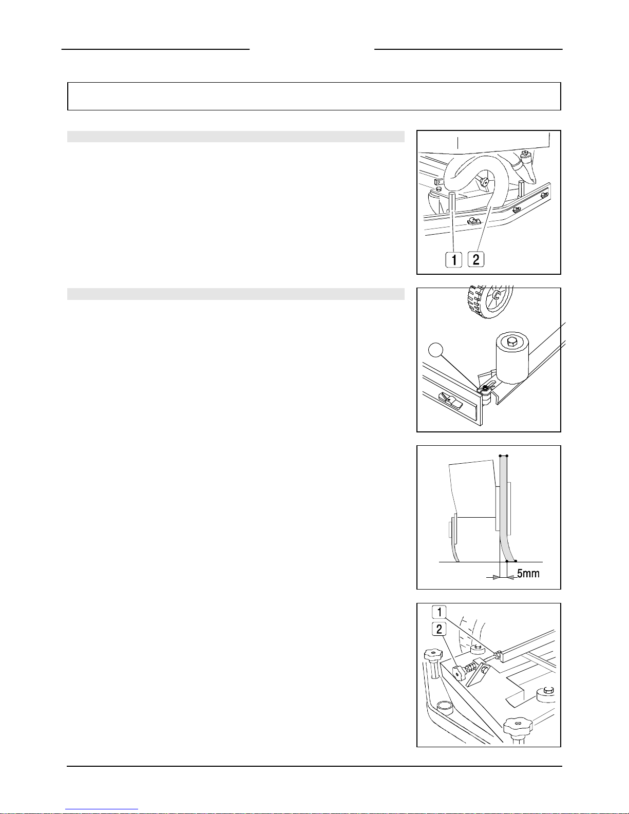
8. SQUEEGEE
Figure 10
The squeegee, which for packing reasons is delivered separated from the machine,
must be assembled as indicated in the drawing by hooking the stud bolts (1-MAGNA
85) of the squeegee into their seat on the squeegee support fixing them with a key
CH17.
Insert the suction hose (2) with its coupling and fix it with the appropriate clamp.
9. ASSEMBLY; SIDE BARS 85S-100S
Figure 11
The side-bars are already fixed to the front part, but it is necessary to place the back
part. Therefore proceed as follows:
1. Insert the back part of the side bar into the pin of the squeegee
2. Insert the fixing clip
3. Repeat the same operations for the second side bar
1
Figure 12
During working operation, the rear rubber should tilt backwards slightly and equally
along its whole length by about 5 mm.
This allows for all four leading edges of the squeegee to be used before it neds to be
replaced.
Figure 13
If it is necessary to increase the rubber deflection in the central part, tilt the squeegee
body backwards, loosen the adjuster nut (1) and rotate the knob (2) counter-clockwise.
If the rubber deflection is to be noticeable at the sides of the squeegee, loosen the
adjuster nut (1) and rotate the knob (2) clockwise. After regulations are completed
tighten the adjuster nut.

12
MACHINE PREPARATION
10. ADJUSTMENT; SQEEGEE HEIGHT SUPPORT
Figure 14
The squeegee has to be regulated in height depending on the wear on the rubbers. To
adjust this:
Loosen the ring nut (1)
With a key CH17 rotate the castor wheel through the nut (2) clockwise to lift the
squeegee and counter-clockwise to lower it
Fix the ring nut (1)
NOTE: The right and left castor wheels should be regulated equally.

13
MACHINE PREPARATION
11. BRUSHES ASSEMBLY; MAGNA 85-100
Magna 85/100
Figure 15
1. Connect the battery connector
2. Turn the key to the ‘ON’ position
3. With the manipulator lift the brushes base
4. Turn the key to the ‘OFF’ position and remove it from the instrument
board (to carry out the operations of brushes assembly with connected
current can cause injury).
2
1 3
4
Figure 16
5. With the brushes base in lifted position, insert the brushes into the
seat of the plate under the base until the three buttons fit into the
holes of the plate. Turn the brush so that the buttons are pushed
towards their retaining springs until the brush is clamped in place. The
figure shows the direction of rotation for the coupling of the right
brush. The left brush has to be rotated inversely.
Figure 17
6. It is recommended to change daily the position of the right brush with
the left one and vice versa. If the brushes are not new and they show
deformed bristles, it is better to reassemble them in the same position
(the right to the right side and the left to the left side), to avoid that
the different inclination of the bristles causes an overload to the
brushes motor and /or excessive vibrations.

14
MACHINE PREPARATION
12. SOLUTION WATER
Figure 18
Fill the solution tank with clean water at a temperature not more than 50°C and add
liquid detergent in the proper concentration following the instructions of the
manufacturer. Excess foam in the recovery tank could damage the suction motor, so
use only the minimum amount of detergent necessary.
NOTE: Always use low foam detergent. To avoid the production of foam, before
starting to clean, put a minimum quantity of antifoam liquid into the recovery tank.
Never use pure acid.
13. RECOVERY TANK
Figure 19
Check that the hopper (2) is closed properly,
Figure 20
and that the exhaust plug of the tank is closed
Figure 21
and the plug of the exhaust hose is closed.

15
GENERAL RULES OF SECURITY
The rules below have to be followed carefully in order to avoid damages to the operator and to the machine.
r Read the labels on the machine carefully. Do not cover them for any reason and replace them immediately if damaged
r The machine must be used exclusively by authorized staff that have been instructed in its use
r During the working of the machine, pay attention to other people and especially to children
r Do not mix different detergents, avoiding harmful odours
r Do not place any liquid containers onto the machine
r The storage temperature has to be between -25°C and +55°C
r The perfect operating temperature should be between 0°C and 40°C
r The humidity should be between 30 and 95%
r Do not use the machine in explosive atmosphere
r Do not use the machine as a means of transport
r Do not use acid solutions which could damage the machine and/or persons
r Avoid working with the brushes when the machine stands still, in order to avoid floor damage
r Do not vacuum inflammable liquids
r In case of fire, use a powder extinguisher. Do not use water
r Do not strike shelvings or scaffoldings, where there is danger of falling objects
r Adapt the speed to the adhesion conditions
r Do not exceed the gradient limit in order to avoid conditions of instability
r When the machine is in parking conditions, remove the ignition key and insert the parking brake
r The machine has to carry out the operations of washing and drying simultaneously. Different operations have to be carried
out in areas which are not permitted for the passage of staff or the public. Cordon off the areas of moist floors with
suitable signs
r If the machine does not work properly, check by conducting simple maintenance procedures. Otherwise, it is better to ask
for FIMAP technical service
r If parts have to be replaced, ask for ORIGINAL spare parts from an agent and/or from an authorized dealer
r In case of danger act immediately upon the emergency lever (connector placed on the left side of the operator)
r For any maintenance operation emove the power supply from the machine.
r Do not leave off any covers which require the use of tools to be removed
r Do not wash the machine with direct water jets or with high water pressure nor with corrosive liquids
r Every 200 working hours have the machine checked by a FIMAP service department
r The machine should not be abandoned, because of the presence of toxic-harmful materials (batteries, oil etc.). This disposal
must be subject to the rules which provide for its scrapping in appropriate centres
r The machine does not cause dangerous vibrations
16
PERFORMANCE
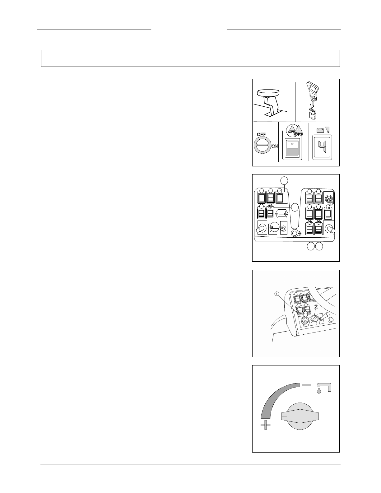
Figure 22
1. Carry out the operations for the preparation of the machine
2. Sit on the driver’s seat
3. Check that the parking brake is released (1)
4. Connect the connector to the batteries (2)
5. Turn the key of the general switch (3) clockwise a quarter turn. Immediately, the
red signal lamp (4) on the instrument board begins to blink and the batteries’
display (5) comes on. The blinking indicates that the checking of the brushes motor
is taking place.
3
1
2
4 5
Figure 23
6. Place the switch into its automatic position (1)
7. Press the suction motor switch (2)
8. Press the switch of the brushes motor (3)
9. Press the solenoid valve switch (4)
Figure 24
10. Place the drive selector (1) in forward position
11. Select the speed movement by rotating the knob (2)
Figure 25
12. Open the cock rotating the knob (1) counter clockwise. The signal lamp of the
water comes on only during the moving period.
MAN
AUTO
AUTO
MAN
1
4 3
2
17
PERFORMANCE
Figure 26
Magna 85/100
13. Push forward the brushes manipulator (1) in order to lower the base. During the
descent, the signal lamps of the actuator and the brushes motor come on. The
brushes base will be in its working position when the yellow signal lamp (2)
switches off.
Magna 85S/100S
14. Push forward the brushes manipulator (3) in order to lower the base. During the
descent, the signal lamps of the actuator and the brushes motor come on. The
brushes base will be in its working position when the yellow signal lamp (4)
switches off.
4
3
1
2
Figure 27
Press the accelerator pedal. The machine begins to move, the squeegee begins to
lower itself and the suction motor comes on.
During the first few metres of operating, check that the brush pressure is suitable
(see further on under “BRUSH PRESSURE”), that the quantity of detergent solution
is sufficient and that the squeegee dries perfectly.
The machine will now start to work efficiently until the detergent solution runs
out.
Figure 28
Immediately disconnect the emergency lever (1) situated on the left side from the
operator and apply the emergency brake (2), whenever problems occur during
work. These commands disconnect all the functions on the machine. To start the
machine again, once the problem has been solved, turn off the key (3), reconnect the
connector (1), switch on the key (3) and lower the parking brake lever (2).
Figure 29
The machine will not start if the operator is not properly seated.
When the solution tank is empty, the signal lamp on the instrument board comes on.
When the recovery tank is full, the suction motor stops. To start it up again, even if
the tank has been emptied, it is necessary to first turn off the main switch key and
then on again.
18
PERFORMANCE
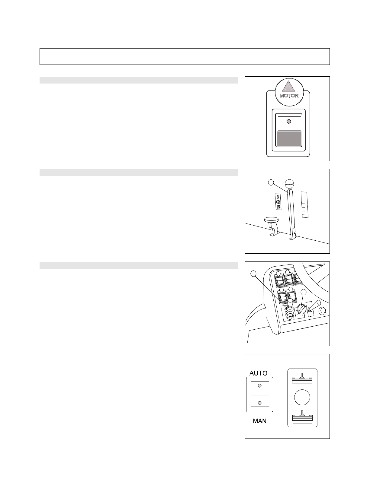
CHECK MOTOR BRUSHES
Figure 30
The brushes motor is electronically controlled. If it reaches established overload limits,
the red signal lamp (1) on the instrument board starts to blink. After a few seconds the
motor stops and the signal lamp of the brushes switch goes off. To start up the motor
again, turn the main switch key (2) off and on again. If the motor stops again, check
the reason of the overload to prevent motor damage. Generally, it is enough to reduce
the brushes pressure.
BRUSH PRESSURE
Figure 31
It is possible to adjust the brush pressure using the proper lever (1) placed on the left
side of the operator. To increase the pressure, push the lever downwards.
The pressure must be chosen based on the type of floor and the type of dirt. Excessive
pressure causes higher brushes wear and a major energy consumption (for further
information read on “CHOICE AND USE OF BRUSHES”)
TRACTION
Figure 32
These machines are equipped with electronically commanded traction, with three
speeds forwards and one backwards. To move the machine, it is necessary to turn the
key and then move forwards (forward movement) or backwards (rear movement) the
manipulator (1). Press the drive pedal and the machine will start to move. The
movement speed can be adjusted rotating the selector (2) also when the machine is in
motion.
Figure 33
NOTE: During reverse motion, if the switch automatic-manual of the squeegee is in
‘manual’ position (1), remember to lift the squeegee through the commutator (2).
During transfer, put the switch onto manual.
1
2
1
1
2

19
PERFORMANCE
SQUEEGEE; AUTOMATIC – MANUAL
Figure 34
Automatic: If the switch is placed on automatic, lowering of the squeegee is obtained
with the machine advancement. Also, lifting of the squeegee is achieved with the
reverse motion of the machine.
Manual: If the switch is placed on manual, the squeegee has to be lifted and lowered
manually through the commutator (2).
The operation of the suction motor is independent from the squeegee position and it
is controlled only by the suction switch.
1
2
BRAKES
Figure 35
To brake, press with the left foot the pedal of the service brake (2).
2
BRAKES
Figure 36
In case of poor operation of this brake, or in case of necessity (interruption, danger),
act upon the parking brake (1).
1
HORN
Figure 37
The machine is equipped with a horn switch. To operate it, press the push button as
shown in the figure.
MAN
AUTO
AUTO
MAN

20
PERFORMANCE
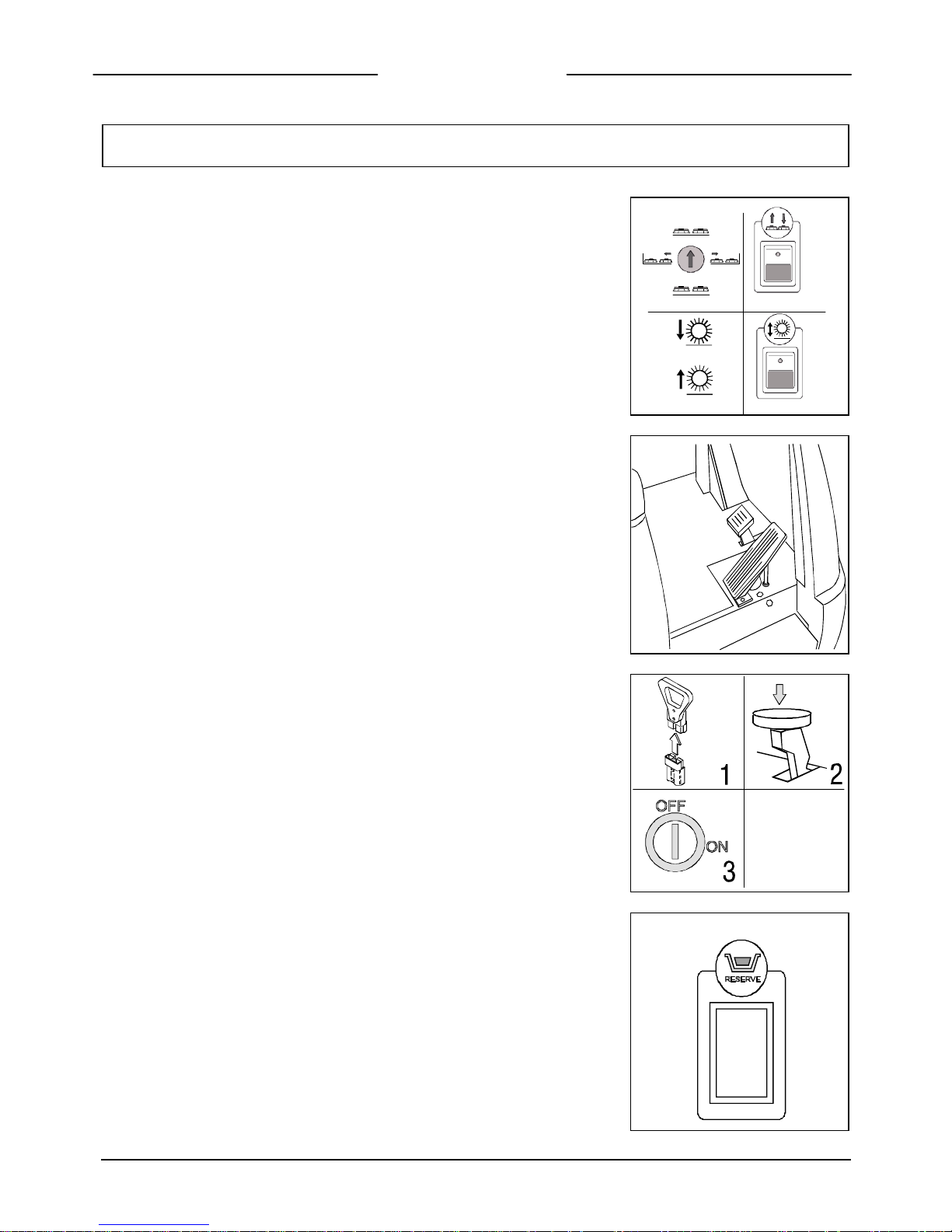
BLINKING AND WORKING LIGHTS
Figure 38
The machine is equipped with blinking lights. For their operation press the switch as
shown in the figure.

21
ON COMPLETION OF WORK
Figure 39
Magna 85/100
Having finished the job and before any type of maintenance is done:
1. Close the cock
2. Raise the brushes base
3. Switch off the brushes motor switch
4. Switch off the solenoid valve switch
3
1
2
4
Figure 40
Magna 85S/100S
Having finished the job and before any type of maintenance is done:
1. Close the cock
2. Raise the brushes base
3. Switch off the brushes motor switch
4. Switch off the solenoid valve switch
3 43
1111 2
Figure 41
5. Place the squeegee switch onto manual
6. Lift the squeegee
7. Switch off the suction motor switch
8. Bring the machine up to the place provided for the water outlet
9. Turn the key 1/4 round counter clockwise
AUTO
MAN
7
5
6
9
Figure 42
10.Remove the exhaust hose from its hook, unscrew the exhaust plug and empty the
recovery tank. To simplify draining operation, it is recommended to hold the hose
bent with one hand and with the other unscrew the knob and take off the plug.
Slowly straighten the hose and the liquid will start draining at the desired speed.
This operation should be carried out using gloves to protect from contact with
dangerous solutions

22
ON COMPLETION OF WORK
11. The squeegee has to be lifted when the machine is not operating. In this way
damage to the squeegee rubbers is avoided.
12. Take off the brushes and clean them with a water jet (for the brushes removal
please read further on under “REMOVAL OF THE BRUSHES”)
13. Clean the dirt hopper (only for Magna 85S 100S) (see the paragraph “DIRT
HOPPER CLEANING)

23
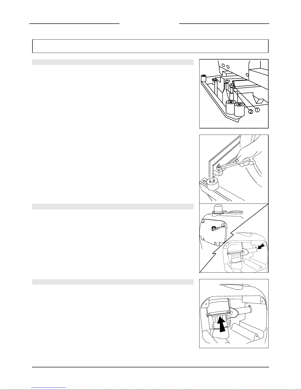
DAILY MAINTENANCE
CLEANING OF THE RECOVERY TANK
Figure 43
1. Empty the tank through the flexible hose, unscrewing with some turns the knob
and then taking off the plug
Figure 44
2. Open the side plug by unscrewing the knob and rotating the closing blade
3. Rinse the tank and clean the exhaust plug
4. Check the perfect position of the side plug gasket
5. Retighten the side plug and the plug onto the exhaust hose
CLEANING THE SQUEEGEE
Clean the squeegee with a water jet. Check the rubber wear and if necessary, turn
them upside-down or change them. The careful cleaning of the complete suction
group assures higher life of the suction motor.

24
DAILY MAINTENANCE
REPLACEMENT OF THE SQUEEGEE RUBBER
Figure 45
If the squeegee rubber is worn and does not dry well, it is possible to
change the drying edge proceeding as follows:
1. Push and rotate the fixing plates
2. Slip off the rubber blade and the rubber itself
3. Turn the rubber upside-down and if necessary, replace it
4. Adjust the squeegee height as indicated in “ADJUSTMENT HEIGHT
SQUEEGEE SUPPORT” under “MACHINE PREPARATION”
5. Reassemble everything in reverse to the above mentioned operations
REMOVAL OF BRUSHES; MAGNA 85/100
Figure 46
1. Connect the battery connector if it is not connected
2. Turn the key into position ON
3. With the manipulator lift the brushes base
4. Turn the key into position OFF and remove it from the instrument
board (to carry out the operations of brush disassembly with
connected current can cause injury)
2
1 3
4
Figure 47
5. With the brushes base in lifted position, rotate the brush until it comes
off from the brush plate seat as shown in the figure. The figure shows
the rotating direction for the disassembly of the right brush, the left
one has to be rotated inversely.

25
DAILY MAINTENANCE
REMOVAL OF THE CYLINDRICAL BRUSHES; MAGNA 85S-
100S
Figure 48
1. Connect the battery connector if it is not connected
2. Turn the key into position ON
3. With the manipulator lift the brushes base
4. Turn the key into position OFF remove it from the instrument board
(to carry out the operations of brush removal with connected current
can cause injury)
1
2 4
3
Figure 49
5. Unfasten the side bars taking out the pin that fixes them to the
squeegee (1)
Figure 50
6. Unscrew the knob (1) and remove the movable plate of the brush
support (2)
26
DAILY MAINTENANCE
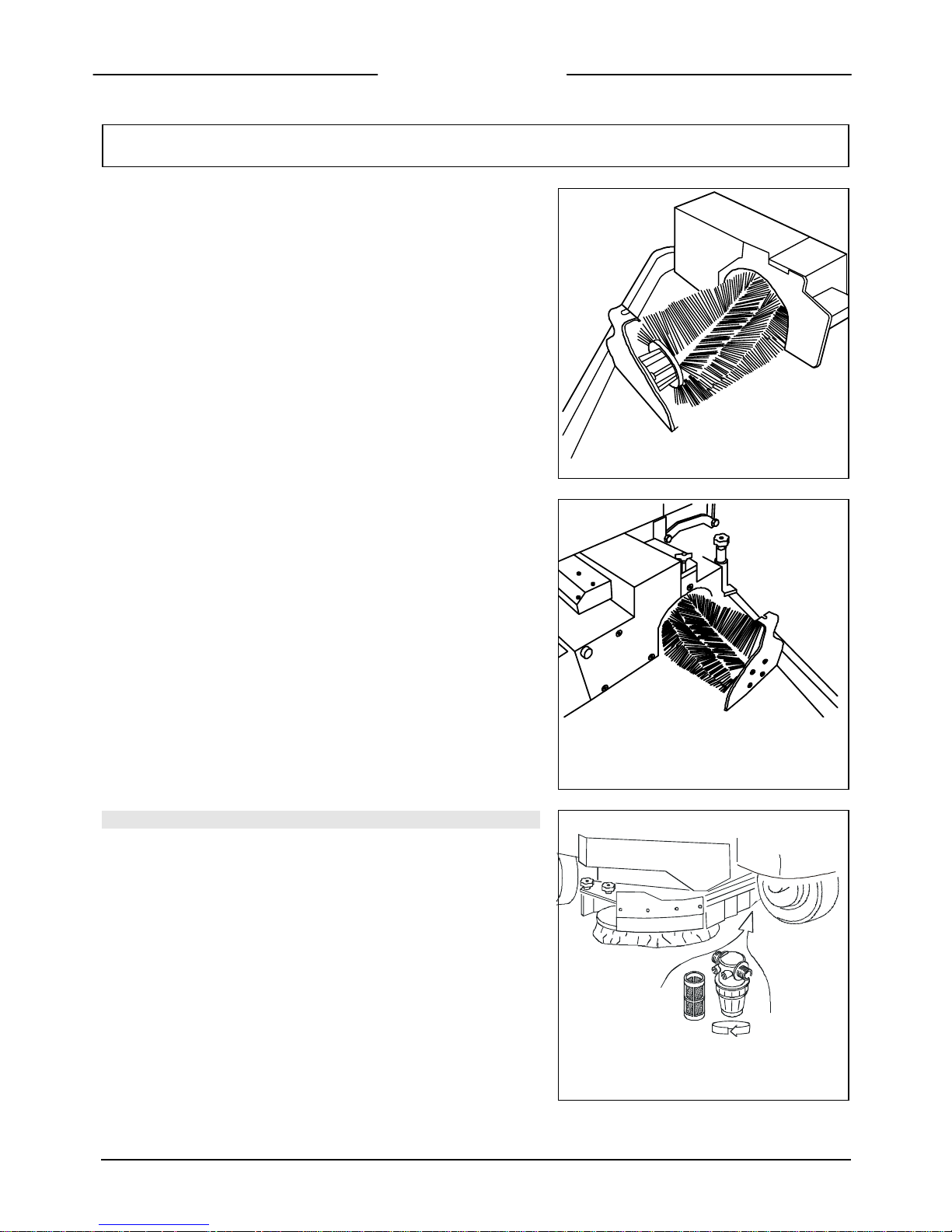
Figure 51 (Left broom)
7. Remove the brush checking the bristles inclination in order to be able
to reassemble it in the same way
Figure 52 (right broom)
Remove the brush checking the bristles inclination in order to be able to
reassemble it in the same way
SOLUTION TANK AND FILTER CLEANING
Figure 53
When the solution tank is empty:
1. Unscrew the filter and rinse the inside thoroughly
2. Take off the cartridge and clean it
3. Open the cock
4. Reassemble everything in reverse order the above operations
27
DAILY MAINTENANCE
DIRT HOPPER CLEANING
Figure 54
Magna 85S/100S
1. Take the pin out of the right side bar and rotate it outwards
2. Unfasten the bolt of the hopper (1)
3. Remove the hopper (2) and clean it
4. Take off the filter (3) and clean it
5. Reassemble in reverse order the above operations

28
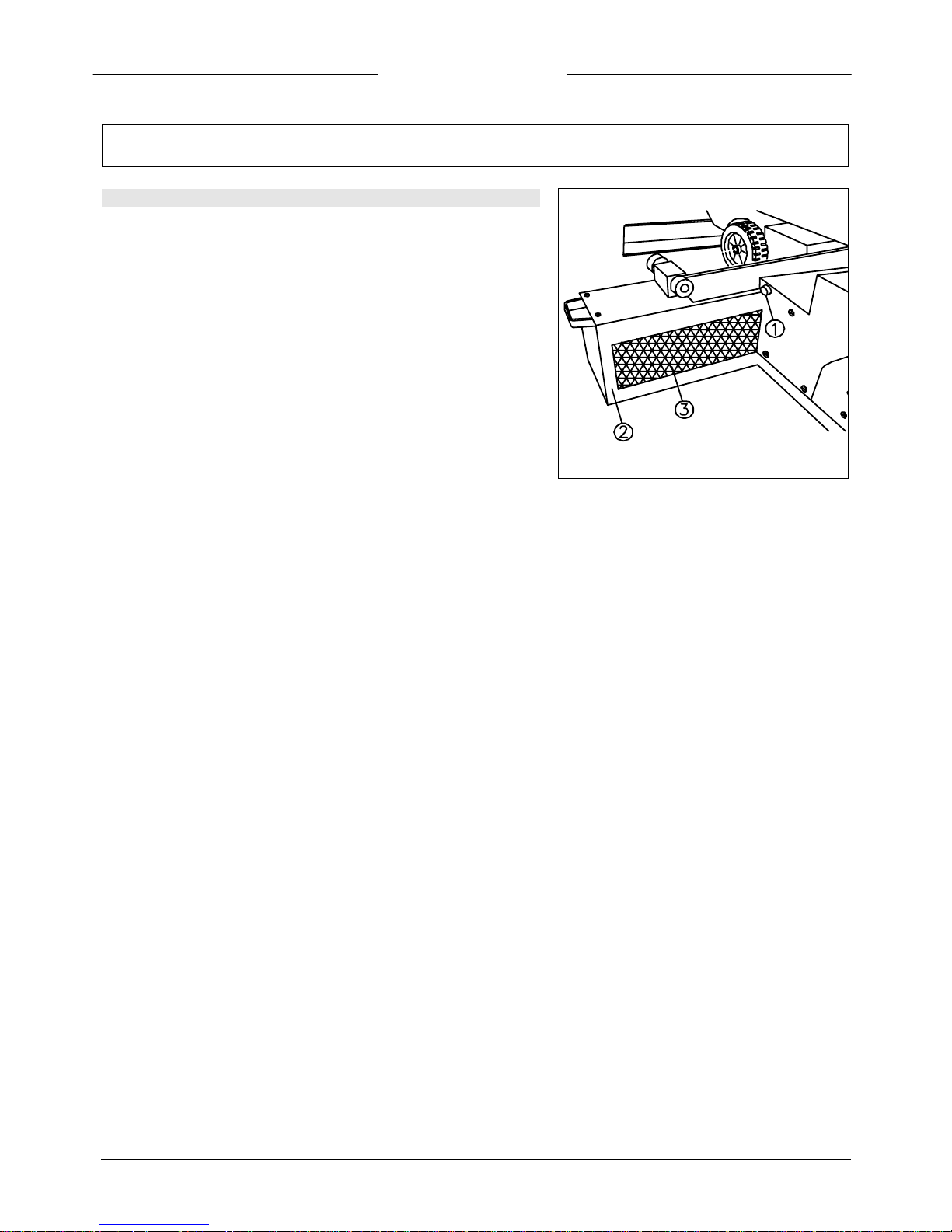
DAILY MAINTENANCE
ADJUSTMENT; SPLASH GUARD BRUSHES BASE MAGNA 85
Figure 55
Periodically proceed with the height adjustment of the side covers of the brushes base.
This operation has to be carried out with the brushes base down.
1. Loosen the fixing knobs of the covers
2. Slip off the covers from their seats
Figure 56
3. Tighten the upper nut with a key CH17 as much as necessary
4. Put the covers back into their position
5. Retighten the knobs
Keep in mind that the rubber must skim the floor and be parallel to it. This is verified
when the nuts have been tightened equally on both stud bolts.
ADJUSTM
ENT; SPLASH GUARD BRUSHES BASE MAGNA 100
Figure 57
Periodically proceed with the height adjustment of the side covers of the brushes base.
This operation has to be carried out with the brushes base down.
1. Loosen the fixing screws of the covers (1)
2. Slip off the covers from their seats
3. Tighten the upper nut (2) with a key CH17 as much as necessary
4. Put the covers back into their position
5. Retighten the screws.
Keep in mind that the rubber must skim the floor and be parallel to it. This is verified
when the nuts have been tightened equally of both stud bolts.
29
WEEKLY MAINTENANCE
ADJUSTMENT; SIDE BARS MAGNA 85/S 100/S
Figure 58
Periodically proceed with the height adjustment of the side-bars. This operation has to
be carried out with the base lowered.
1. Loose the knob (1)
2. Tighten the adjuster (2) to lift the side bar or unscrew the adjuster (2) to lower the
side bar
3. When the adjustment has been completed, fix the knob (1)
Figure 59
4. Take off the retaining clip
5. Take off the side bar
6. Adjust the height of the support nut
7. Put the side bar and the retaining clip back into their position
Keep in mind that the side bars must be parallel to the floor
These adjustments have to be carried out on both side bars
CLEANING OF THE SUCTION HOSE
Figure 60
Whenever suction seems to be unsatisfactory, check that the suction hose is not
obstructed. Eventually, clean it with a water jet introduced from the side where it is
connected to the tank. Proceed as follows:
1. Unscrew the four screws and take off the suction motor cover
2. Loosen the clamp which tightens the hose
3. Clean with a water jet introduced from the side where it is connected to the tank
4. Reassemble everything in reverse order to the above mentioned operations
CLEANING SUCTION MOTOR FILTER
Figure 61
Unscrew the four screws and take off the suction motor cover
2. Unscrew the three knobs which fix the suction motor to the support
3. Take off the suction motor
4. Extract the filter and clean it thoroughly
Reassemble everything in reverse order to the above operations.
30
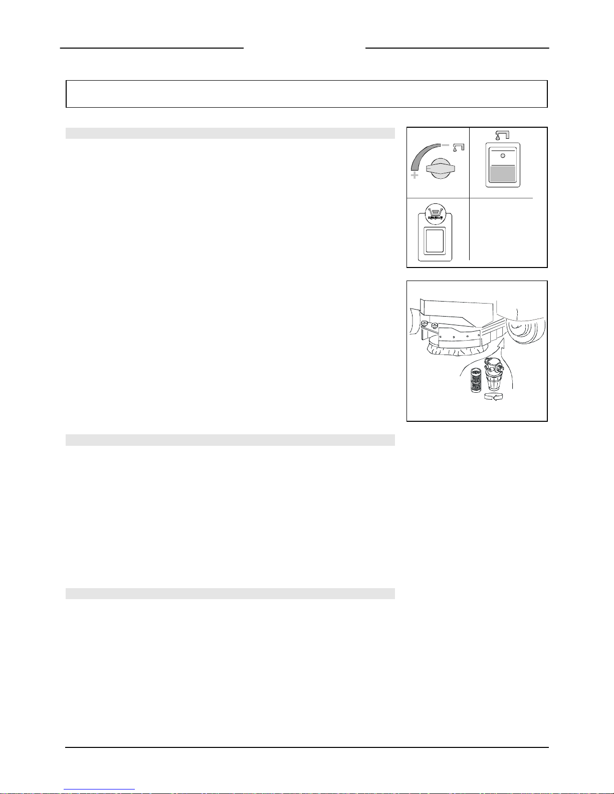
TROUBLE SHOOTING GUIDE
INSUFFICIENT WATER ONTO THE BRUSHES
Figure 62
1. Make sure that the cock is open
2. Check that the solenoid valve switch is on
3. Make sure that there is water in the solution tank (signal lamp “RESERVE” off)
3
1 2
Figure 63
4. Clean the solution filter
THE MACHINE DOES NOT CLEAN SATISFACTORILY
1. Check the conditions of the brushes and replace them, if necessary. The cylindrical
brushes have to be replaced when the bristles reach around 15 mm for Magna
85/100 and 10 mm for Magna85S/100S).
2. Check that the pressure on the cylindrical brushes is sufficient, eventually increase
it (see “PRESSURE CYLINDRICAL BRUSHES” under “PERFORMANCE”).
3. Use different kind of brushes to the ones fitted as standard. For cleaning
operations on floors where the dirt proves to be particularly resistant, we
recommend using special brushes which may be supplied optionally according to
needs (see under “CHOICE AND USE OF BRUSHES”).
THE SQUEEGEE DOES NOT DRY PERFECTLY
1. Check that the squeegee is clean
2. Check the squeegee adjustments (see under “MACHINE PREPARATION”)
3. Clean the whole suction group (see under “WEEKLY MAINTENANCE”)
4. Replace the rubbers, if worn
31
TROUBLE SHOOTING GUIDE
THE SUCTION MOTOR DOES NOT FUNCTION
Figure 64
1. Check that the suction motor switch is on
2. Check whether the recovery tank is full and eventually empty it
Figure 65
3. Check the perfect condition of the float switch (see also “CLEANING OF THE
RECOVERY TANK FILTER” under “DAILY MAINTENANCE”)
4. To reactivate the suction motor, after operation of the float switch, switch off and
then on again the main switch key.
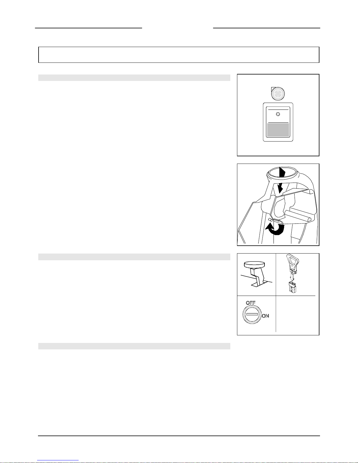
THE MACHINE DOES NOT START
Figure 66
1. The operator must be properly seated in the driving position
2. Check that the hand brake lever is completely released
3. Check that the general switch key is In the ‘ON’ position
4. Check that the connector is connected to the batteries
3
2
4
EXCESSIVE FOAM PRODUCTION
Check that a low foam detergent has been used. If required, add a small quantity of
antifoam liquid into the recovery tank.
Remember that, when the floor is not very dirty, more foam is generated. In this case
dilute the detergent further.

32
CHOICE AND USE OF BRUSHES
POLYPROPYLENE BRUSH (PPL)
It is used on all types of floors which are hot water resistant (not more than 60°C). The Polypropylene brush is non-hygroscopic
and therefore conserves its characteristics even if working in wet conditions.
NYLON BRUSH
It is used on all types of floors with excellent wear and hot water resistance (more than 60°C). The nylon is hygroscopic and so,
over time, looses its characteristics working on the wet.
TYNEX BRUSH
The brush bristles are charged with very aggressive abrasives. It is used to clean very dirty floors. To avoid floor damages, work
strictly only with the necessary pressure.
STEEL BRUSHES
Bristles are made of steel wire or flat blades or are mixed steel and synthetic fibres. The steel wire brush is used to remove scale
from badly uneven floors or floors with wide joints between tiles. Brushes with flat steel bristles (stiffer) are used to clean the
toughest scale.
THICKNESS OF THE BRISTLES
The thicker the bristles are, the more rigid they will be. These ones are therefore used on smooth floors or with small joints.
On uneven floors with deep joints it is recommended that, softer bristles, which enter more easily in depth, be used.
Please bear in mind that, when the bristles are worn out and get too short, they will get rigid and cannot penetrate anymore.
As well as for thick bristles, the brush will begin to jump.
PAD HOLDER
The pad holder is recommended to clean glossy areas.
There are two types of pad holders:
1. The traditional pad holder is equipped with anchor points which allow the abrasive pad to be held and dragged during the
work process.
2. The pad holder is of the CENTER LOCK type, apart from the anchor points, is equipped with a central locking release system
made of plastic. This allows a perfect match with the abrasive pad and to hold it without the risk of falling down. This type of
pad holder is recommended especially for machines with more brushes, where the centreing of the pads is difficult.
BRUSH CHOICE LIST
Machine Q.ty Code Bristles type Ø bristles Ø Brush Notes
Magna 85 2
E6803040
E6814020
E6814030
E6703010
PPL
NYLON
TYNEX
Pad holder
0.9
1.2
1.5
430
430
430
410
Magna 100 2
E6821020
E6821040
E6727010
PPL
TYNEX
Pad holder
1
1.5
510
510
505
CYLINDRICAL BRUSH CHOICE LIST
Machine Q.ty Code Bristles type Ø bristles Ø Brush
Length
Colour
Magna 85/S 2
E6814040
E6814050
PPL
TYNEX
0.1
1/0.6
210
210
862
862
BLACK
GREY
Magna 100/S
2
2
E6827010
E6827020
PPL
TYNEX
0,1
1/0,6
210
210
1012
1012
BLACK
GREY
 Loading...