

Luzchem SPR-02, SPR-01 Instruction Manual

Spectroradiometers
Instruction manual
SPR-01 and SPR-02
Version 2.3
August 2004
© Copyright Luzchem Research, Inc.

Table of Contents
1. Initial set-up ......................................................................................................... 3
1.1. Model SPR-01............................................................................................. 3
1.2. Model SPR-02............................................................................................. 3
2. Understand your hardware................................................................................... 4
2.1. Detector head.............................................................................................. 4
2.2. Spectrometer............................................................................................... 5
2.3. Fiber optic cable.......................................................................................... 5
2.4. Attenuator ................................................................................................... 6
2.5. Verification lamp (model SPR-01 only).....................................................6
3. Software Instruction manual................................................................................ 8
3.1 General........................................................................................................ 8
3.2 Software Installation...................................................................................8
3.3 Starting the software................................................................................... 9
3.4 Optimize Integration Time.......................................................................... 9
3.5 Power/Intensity Spectra............................................................................ 10
3.6 Data reliability evaluation......................................................................... 12
3.7 Timed Acquisition .................................................................................... 13
3.8 File Formats.............................................................................................. 15
4. Help ................................................................................................................... 18
2
1. Initial set-up
1.1. Model SPR-01
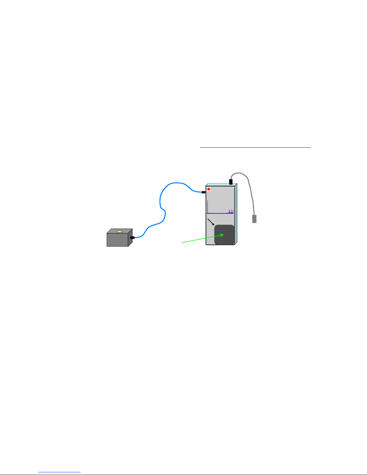
The Spectroradiometer model SPR-01 consists of three parts:
• The control module and detection fiber
• The detection head (light integrating module)
• A USB cable
Assemble the instrument as indicated below. The connection of the blue fiber optic
cable to the detector should be ‘finger tight’. Do not use any tools and do not force.
The calibration parameters for your instrument have been determined with the same
components with which it was supplied. Individual parts are not interchangeable.
Detector
Optical fiber
Verification
lamp
Spectroradiometer
SPR-01 - 235-850 nm
Place detector in
Corner for verification
Control Module
USB cable
Figure 1.1: Schematic diagram for SPR-01
Optical fibers are fragile and cannot be bent at any angle. The minimum momentary
bent radius is 60 mm, and the minimum long term bent radius is 100 mm (4 inches).
Assemble your instrument as indicated above, and connect the USB cable to an
available port in your computer. Software installation is explained in Section 3 of
this manual.
1.2. Model SPR-02
The Spectroradiometer model SPR-02 consists of two parts:
• The control module that with its built-in detection head (light integrating
module)
• A USB cable
SPR-02 is sold fully assembled. Only the USB cable needs to be installed and
connected to the computer. Software installation is explained in Section 3 of this
manual.
3
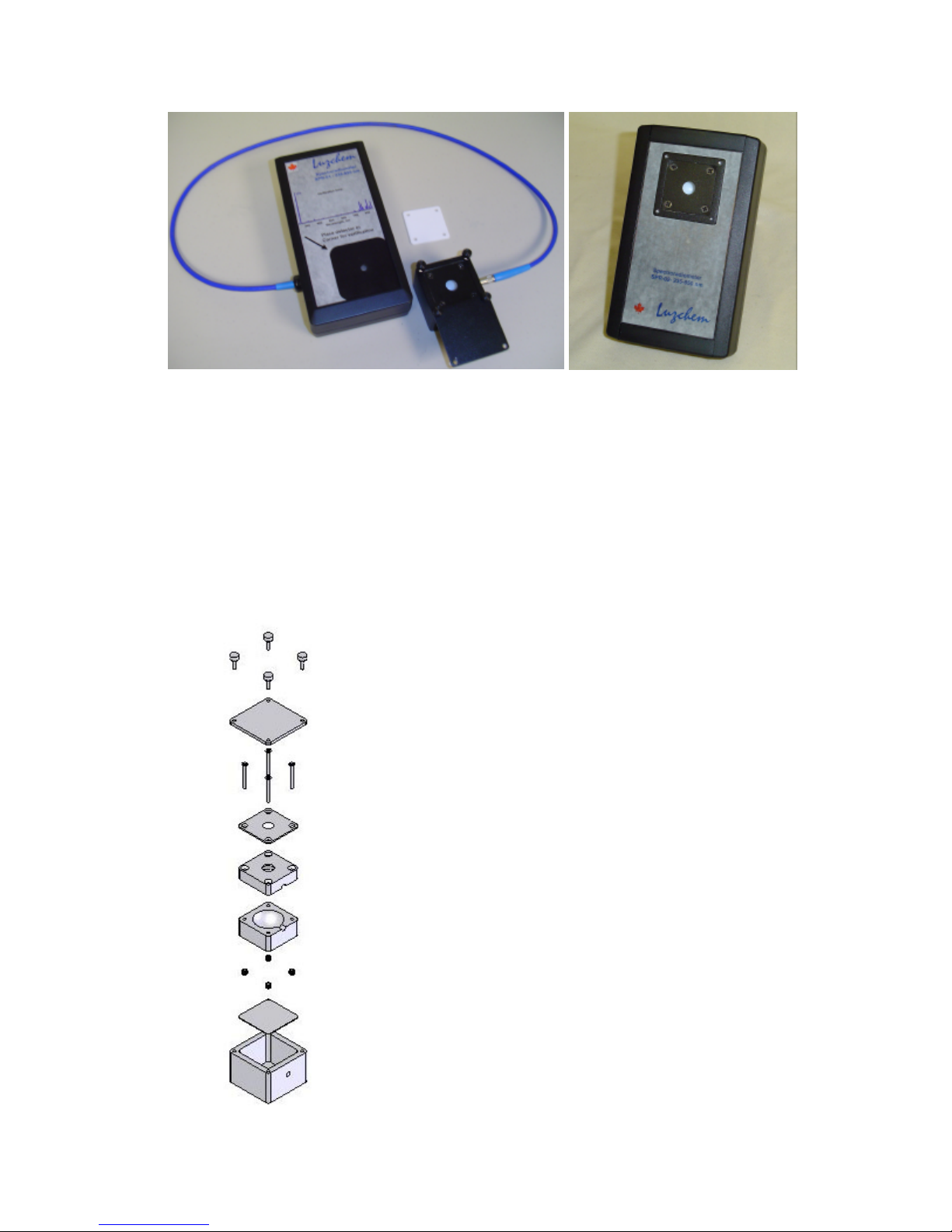
Figure 1.2: Spectroradiometer models SPR-01 (left) and SPR-02
2. Understand your hardware
2.1. Detector head
Figure 2.1 shows the assembly of the detector head or light integrator. The detector is
constructed of PTFE encased in light scattering aluminum and has been designed for
maximum efficiency in a low-profile integrator.
Figure 2.1: Assembly of the detector head
4
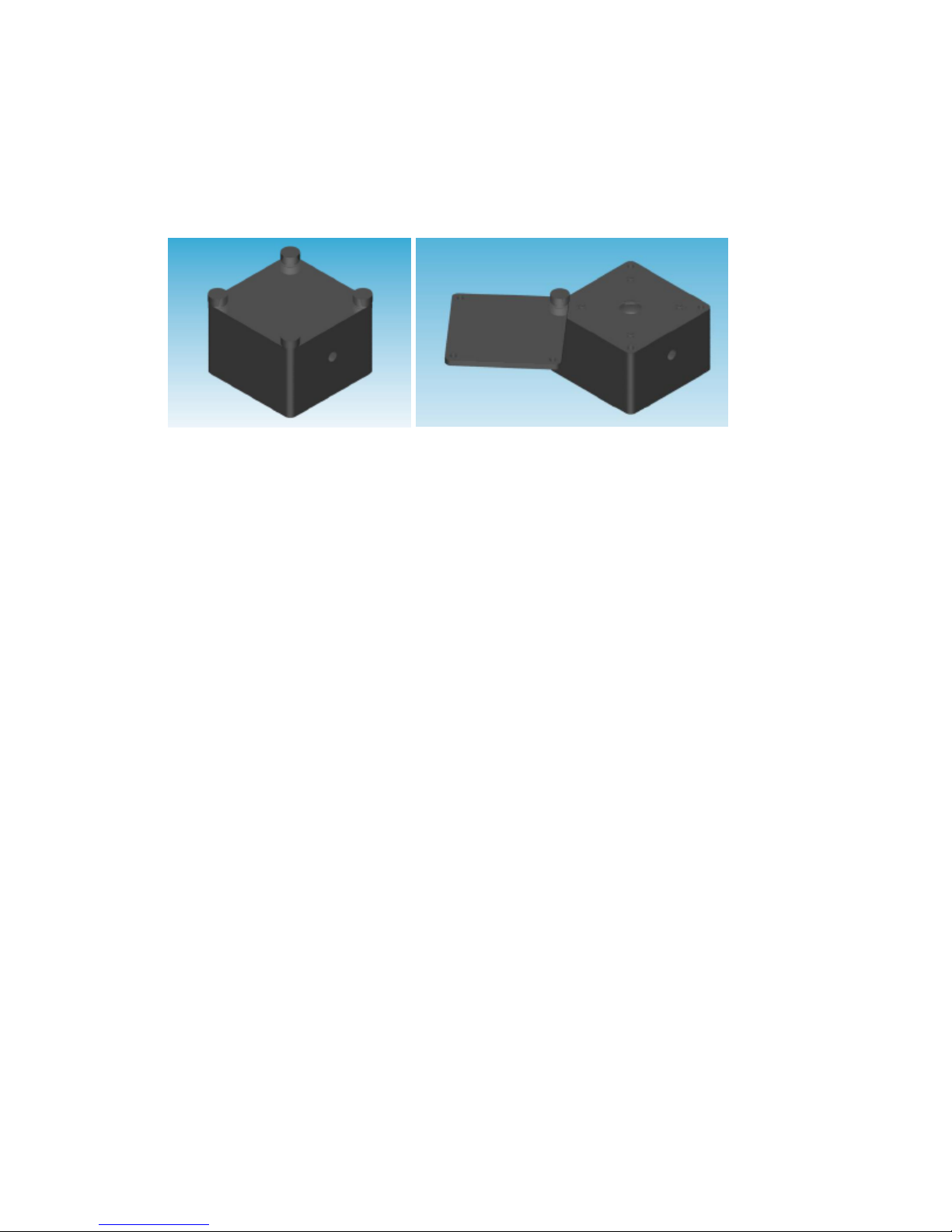
The top of the integrator has a solid cover that can be used when monitoring the dark
background. We have found it convenient to leave one holding screw loosely in
place and simply rotate the cover to monitor dark and light signals, see Figure 2.2.
Figure 2.2: Closed and open detector assembly, as used in Model SPR-01
It is important that you do not allow dust or other materials to fall inside the detector
head; this would invalidate the calibration provided by Luzchem.
The bottom of the detector head has a threaded hole (1//4-20 threads) that can be used
for mounting the detector. A very thin aluminum plate protects the PTFE
compartment from damage by objects inserted through the mounting hole. The
maximum penetration is 3 mm. Do not force screws to penetrate more than this, since
they can damage the integrator compartment.
2.2. Spectrometer
The heart of Luzchem spectroradiometers is a 2048 element spectrometer contained
in the control module. It covers a minimum range of 230 to 860 nm and has optical
components to optimize ultraviolet detection. Data points are acquired about every
~0.3 nm; however the software converts the data so that points are displayed at 1 nm
intervals.
The spectrometer is quite robust and ideal for field work and wherever portability is
important. However, it should be protected for water and high temperatures.
Stray light is quite low, for example: < 0.05% at 600 nm, < 0.10% at 435 nm, and <
0.10% at 250 nm. The grating used has 600 lines/mm and has been blazed at 400 nm.
Spectrometer control is achieved via the USB port; no other source of power is
required to operate the spectrometer.
2.3. Fiber optic cable
The fiber optic cable, connecting the spectrometer to the detector head is an integral
part of your instrument (it is fully enclosed in the spectroradiometer model SPR-02),
and instrument calibration is dependent on the fiber used.
5

The fibers used are terminated with SMA connectors that have been carefully
polished to achieve adequate optical performance. Luzchem uses high-OH fibers to
optimize ultraviolet performance. For model SPR-01 the fiber used is 300 µm in
diameter. The minimum allowed momentary radius is 60 mm (~2.5 inches), and the
minimum long term radius is 100 mm (4 inches). Bending the fiber beyond these
limits can cause permanent damage that also invalidates the calibration factors. Fiber
replacement requires recalibration of the instrument.
Instructions for SPR-01 only
When installing the fiber, the connection should be “finger tight”. Do not use tools
for this purpose.
The female SMA connector on the detector head should not move when installing or
disconnecting the fiber. It has been installed with a special adhesive that under
normal force conditions will prevent the female connector on the detector head from
moving. If this connector moves it will be necessary to reinstall it matching exactly
the calibration distance. Contact Luzchem for assistance.
2.4. Attenuator
Luzchem spectroradiometers are supplied with a PTFE film attenuator that reduces
the light input by about one order of magnitude. A generic transmission curve is
supplied with all attenuators.
Luzchem can perform a custom NIST traceable calibration for the attenuator supplied
with the system. For many applications the attenuator is not essential; however, for
some solar and sunbed applications, the attenuator may be useful to increase the
dynamic range of the instrument.
2.5. Verification lamp (model SPR-01 only)
Model SPR-01 includes a low pressure mercury lamp that operates with 4 AA
batteries. The lamp is controlled by a switch at the back of the instrument. This
switch does not need to be on to operate the radiometer, but only to use the
verification lamp. The verification lamp has the spectrum of Figure 2.3 (this is a
power spectrum), with a characteristic band at 254 nm that should be within ±1 nm of
the wavelength read.
6
 Loading...