

luxvision SL 880 User Manual
USER’S MANUAL
SILT LAMP
SL 880

Notication
Dear Users,
Thank you for your purchase of SL 880 Slit Lamp. Please take time to read our
user’s manual carefully before use.
This guarantees you to make full use of this unit and prolongs the operation life of
this unit.
Precautions
If you have detected abnormal heat, smoke, noise or smell, immediately stop using
the product.
In the event of an abnormality, turn off the power and disconnect the power plug from
the power socket. Continuing to use the product may result in electric shock or re.
Observe the instructions given below regarding the power cable:
• Be sure to use the supplied or specied power cable.
• Do not modify, forcibly bend, kink or pull the power cable.
• When disconnecting the power cable from the AC outlet, be sure to hold the cable
by the plug.
Pulling the cable may cause wire breakage or shot circuit, resulting in re or electric
shock.
• Do not connect or disconnect the plug of the power cable to/from the AC outlet
using wet hands.
Doing so may result in electric shock.
• Do not touch the product with wet hands while the power cable is connected
to the AC outlet.
Doing so may result in electric shock.
• If the product will not be used for a long period, disconnect the power cable
from the power source. Leaving the cable connected to the power socket for
a prolonged period will consume electricity and may result in heating.

Content
1. Name of Parts............................................................................................... 4
2. Assembly....................................................................................................... 7
3. Operation.................................................................................................... 16
4. Maintenance............................................................................................... 22
5. Common Trouble Shooting......................................................................... 28
6. Responsibility.............................................................................................. 29
7. Transportation............................................................................................. 29
8. Optional Accessories.................................................................................. 29
9. Specications.............................................................................................. 31
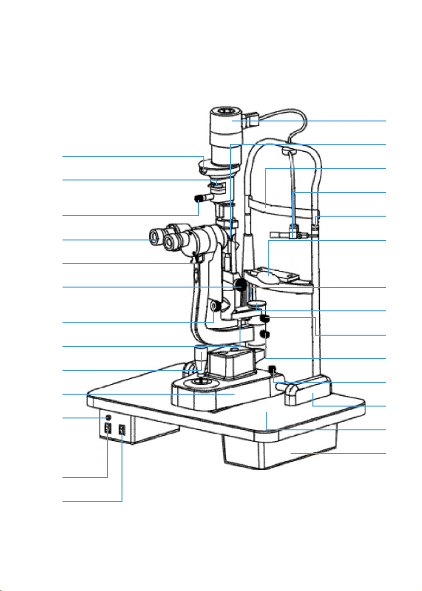
1. Name of Parts
17
16
18
19
20
21
15
14
13
12
11
10
1
4
9
8
7
22
23
24
25
26
27
2
3
5
6
Fig. 1
4

1. Joystick
Incline joystick to move the instrument slightly on the horizontal surface and
rotate it to adjust the elevation of the microscope.
2. Base Locking Screw
The base will be locked when fastening this screw.
3. Rail Cover
Protect the rail surface
4. Base
Support the microscope and the illumination arms with the joystick controlling
its movement.
5. Work Table
6. Accessory Drawer
Store the focusing test rod and other accessories.
7. Brightness Control Switch
Two levels are available – H ( HIGH ), N ( NOR - MAL). Avoid working
continuously at high setting, as the service life of the bulb will be shortened.
8. Main PowerSwitch
9. Pilot Lamp
10. Location Roller
When it is in the middle, it stands for included angle of 0 between the
microscope arm and the illumination arm. And the right or left side the
included angle of 10.
11. Centering Knob
Loosening the knob allows the illumination light to be moved from the center
of the vision led for indirect retro-illumination. Fastening the knob brings
the illumination light back to the center.
12. Slit Width Control Knob
The slit width is continuously adjustable within the range from 0 to 9mm.
13. Magnication Changer Lever
Push the lever of either side to select the desired magnication of the
microscope.
5

14. DiopterAdjustment ring
Adjust the eyepieces diopter to obtain a clear image before using the
instrument.
15. Aperture and Slit Height Control Knob
Rotate this knob to adjust the spot and the slit height. Swing the knob
horizontally to revolve the slit.
16. FilterSelection Lever
There are four lters for selections
17. Slit height and aperture display window
18. Lamp cap
19. Reecting Mirror
The long mirror is provided. The observation pathway may be interfe red if
the included angle between the microscpe arm and the illumination arm
is only 3º - 10º.
20. Forehead Belt
21. Fixation target
An illuminated xed spot for patient to look at.
22. Horizontal Mark
When the horizontal center of the patient’s eye is in line with the mark, the
elevation of the microscope controlled by joystick is also in its center position.
23. Chin-rest
24. Chin-rest elevation adjustment knob
Rotate the knob to adjust the elevation of the Chinrest.
25. Protection cap
Please cover the main shaft hole with the protection to prevent dusts and
physiological salt solution from dropping into the main shaft pole of the
illumination arm during the operation. Take off the cap when assemble the
focusing test rod.
26. Mocroscope and illumination arm couple bolt
Fasten this bolt and illumination arm and the mircroscope arm could be move
in couple state to rotate together. Loosen it and the illumination arm then
6
can rotate separalely.
27. Microscope arm locking knob
Lock the rotational movement of the microscopearm.
2. Assembly
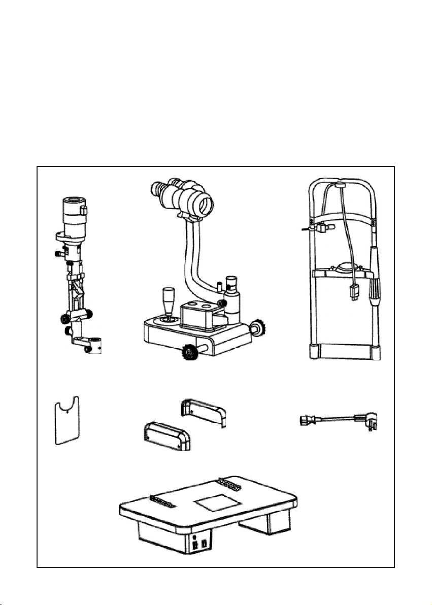
2.1 Components
A B C
D E F
G
7
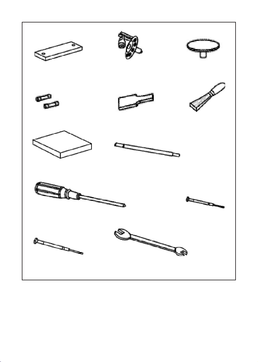
H I J
K L M
N
P Q
R S
O
8
Name Quantity
A Illumination Part
B Base Part (with microscope)
C Head rest part
D Breath shield
E Work table with Power Box
F Rail cover
G Input Power cable
H Chin-rest paper
I Spare main illumination Bulb
J Protection cap
K Spare fuse
L Spare long Reecting Mirror
M Brush
N Dust Cover
O Focusing Test Road
P Cross Screw Driver with Wood handle
Q Watch screw Driver (small)
R Watch screw Driver (big)
S Spaner
(*Optionally available in some region)
2.2 Assembly Procedure
Necessary tools are as follows:
Cross Screw Driver With Wood Handle (P)
Watch screwdriver (R)
Spanner (S)
1
1
1
1
1
2
1
1
1
1
2
1
1
1
1*
1
1
1
1
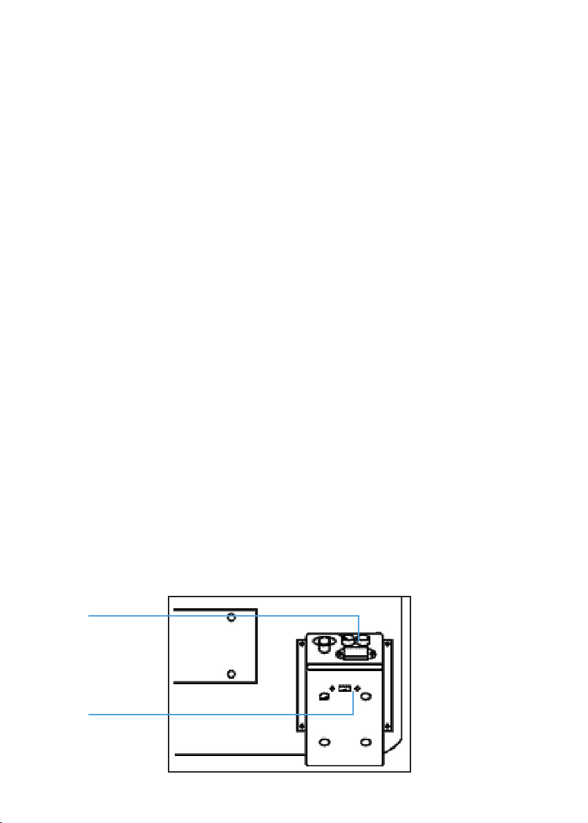
1. Selecting voltage and fuse
Fuse holder
Voltage
selector
9
Selector voltage and fuse
• Check the setting on the voltage selector located on the bottom of the power
box. If it doesn’t match with the input voltage, slide it to the proper position
with screwdriver (R).
• Open the fuse holder with screw driver (P) and take out the fuse, check and
ensure that its rated value iscorresponding to the mains voltage:
110 Volt.....................1A
220 Volt..................... 0.5 A
It has been set to the 220 v 0,5 A before leaving our factory.
Important Matters
Set the input voltage and frequency of the instrument according to that of the mains.
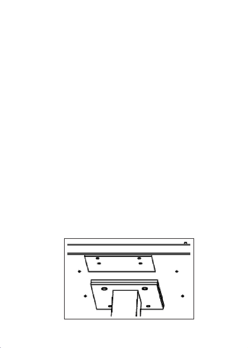
2. Assembling the worktable ( E )
To attach the worktable on the motorizedinstrument table, please screw off
four M8x20mm bolts with spring washers with the spanner (S).
Lift the worktable to aim its screw hole at the assembly hole of the instrument
table.
• Put down the worktable, with the power panel facing the user, refasten the
bolt securely with the spanner.
10
 Loading...