

luxvision SL 1400 User Manual
USER’S MANUAL
SLIT LAMP
SL 1400

Notication
Dear Users,
Thank you for your purchase of SL 1400 Slit Lamp. Please take time to read our
user’s manual carefully before use.
This guarantees you to make full use of this unit and prolongs the operation life of
this unit.
Precautions
If you have detected abnormal heat, smoke, noise or smell, immediately stop using
the product.
In the event of an abnormality, turn off the power and disconnect the power plug from
the power socket. Continuing to use the product may result in electric shock or re.
Observe the instructions given below regarding the power cable:
• Be sure to use the supplied or specied power cable.
• Do not modify, forcibly bend, kink or pull the power cable.
• When disconnecting the power cable from the AC outlet, be sure to hold the cable
by the plug.
Pulling the cable may cause wire breakage or shot circuit, resulting in re or electric
shock.
• Do not connect or disconnect the plug of the power cable to/from the AC outlet
using wet hands.
Doing so may result in electric shock.
• Do not touch the product with wet hands while the power cable is connected
to the AC outlet.
Doing so may result in electric shock.
• If the product will not be used for a long period, disconnect the power cable
from the power source. Leaving the cable connected to the power socket for
a prolonged period will consume electricity and may result in heating.

Content
1. Name of Parts............................................................................................... 4
2. Assembly....................................................................................................... 8
3. Operation.................................................................................................... 19
4. Maintenance............................................................................................... 28
5. Common Trouble Shooting......................................................................... 35
6. Optional Photographic Attachment............................................................. 37
7. Optional Observation Tube.......................................................................... 65
8. Optional TV Accessories............................................................................. 67
9. Optional Barrier Filter.................................................................................. 68
10. Applanation Tonometer................................................................................ 69
11. 12.5x measuring eyepieces......................................................................... 70
12. Resopnsibility............................................................................................... 71
13. Transportation............................................................................................. 71
14. Specications.............................................................................................. 72
1. Name of Parts
24
23
22
21
19
20
18
17
16
15
14
12
13
25
26
27
28
29
30
31
32
33
34
35
36
1
11
10
9
8
7
2
3
4
5
6
4

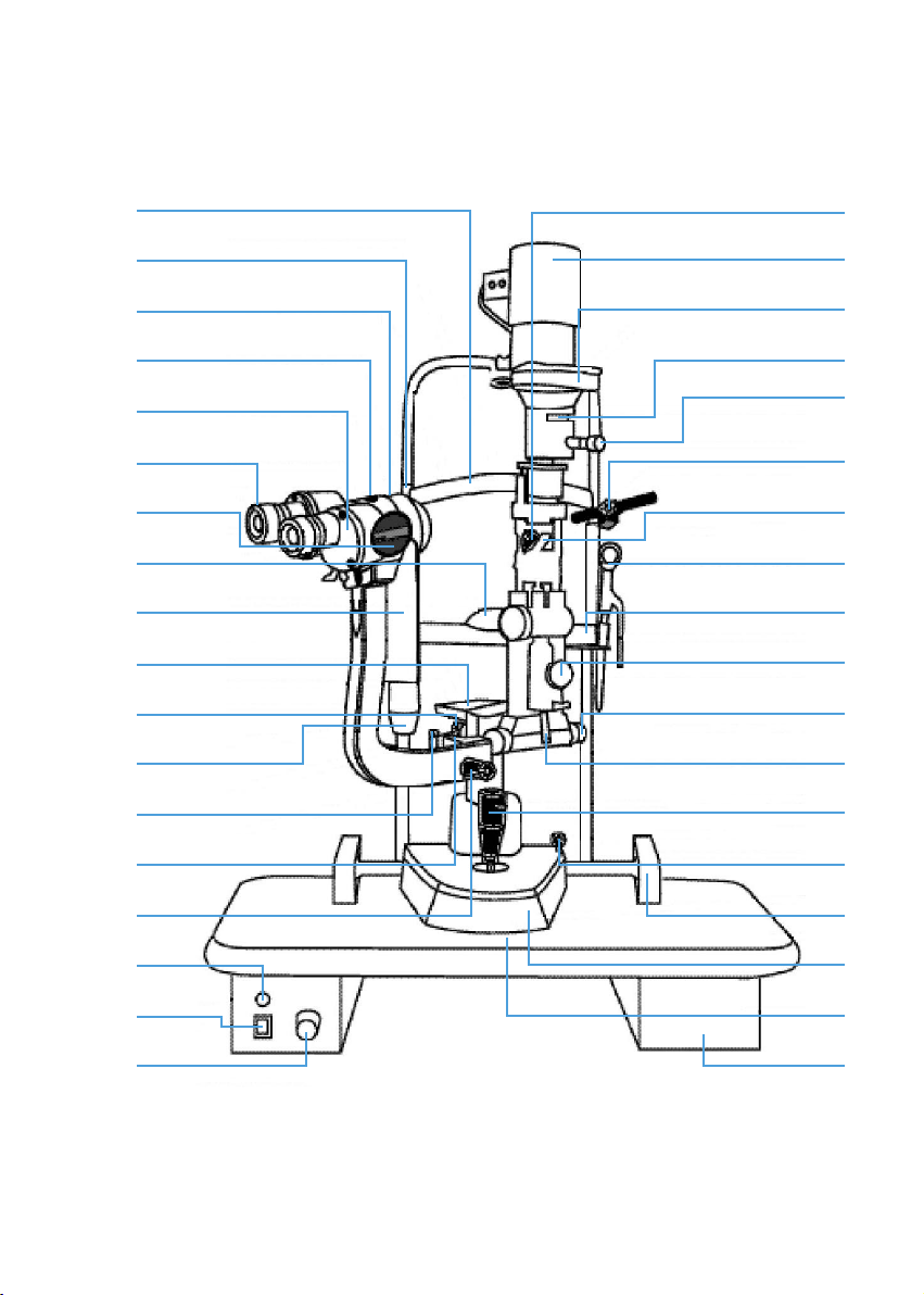
1. Joystick
Incline joystick slightly to move the instrument in the horizontal plane and
rotate it to adjust the elevation of the microscope.
2. Base Locking Screw
The base will be locked when this screw is tightened.
3. Rail Cover
Protects the rail surface
4. Base
Supports the microscope and the illumination arms with the joystick controlling
its movement.
5. Work Table
6. Accessory Drawer
Stores the focusing test rod and other accessories.
7. Brightness Control Switch
Two levels are available – H (HIGH), N ( NORMAL). Avoid working continuously
at the high setting, as the service life of the bulb will be shortened.
8. Main Power Switch
9. Pilot Lamp
10. Microscope Arm Locking Knob
Prevents rotational movement of the microscope arm.
11. Angle Mark Ring
Marks on the angle mark ring of the illumination arm align to the long mark
on the microscope arm. When 0 on the ring aligns to the short mark at one
side of the user, the right eyepiece may be obstructed, and the side of the
patient the left eyepiece.
12. Chin-rest Elevation Adjustment Knob
Rotate the knob to adjust the elevation of the chinrest.
13. Location Roller
When the roller is in the middle, the included angle between the microscope
arm and the illumination arm is 0º, when it is to the right or left the included
angle is 10º.
5

14. Microscope and Illumination arm Coupling Bolt
Tightening this bolt permits the illumination arm and the microscope arm
to be rotated simultaneously. Loosening the bolt allows the illumination arm
and microscope arm to rotate separately.
15. Hruby Lens Guide Plate
The plate is also used for the applanation tonometer.
16. Microscope Fixation Screw
17. Chin-Rest
18. Magnication Select Dial
Five magnications are provided.
19. Prism Boxes
The prism boxes are used to adjust the interpupillary distance.
20. 12.5x Eyepiece
Before use, adjust the diopter ring for each eyepiece to get a clear image.
21. Microscope Fixation Screw
22. Accessory Mount
The accessory mount will accept the Model R-900 Goldmann applanation
tonometer in addition to other accessories.
23. Horizontal Mark
The horizontal center of the patient’s eye is aligned to the mark by changing
the elevation of the microscope using the joystick.
24. Forehead Belt
25. Diffusion Lens
The diffusion lens is used for photographing at low magnications and for
enlarging the eld of magnication.
26. Lamp Cap
27. Aperture height and display window
28. Filter Selection Lever
There are four lter selections.
6

29. Aperture and Slit Height Control Knob
Rotate this knob to adjust the spot and the slit height. Turn the knob
horizontally to rotate the slit.
30. Fixation Target
An illuminated xed spot for patient to look at.
31. Reecting Mirror
Both long and short reecting mirrors are provided.
The long mirror is used for most examination procedures.
The short mirror is used when the long mirror interferes with the optical path
as may happen a during funduscopy.
32. Hruby Lens
Used for observation of fundus and the posterior segment of the vitreous
body.
33. Hruby Lens Holder
34. Centering Knob
Loosening the knob allows the illumination light to be moved from the center
of the eld of vision for indirect retro-illumination. Tightening the knob brings
the illumination light back to the center.
35. Slit Width Control Knob
The slit width is continuously adjustable from 0 to 9mm.
7
2. Assembly
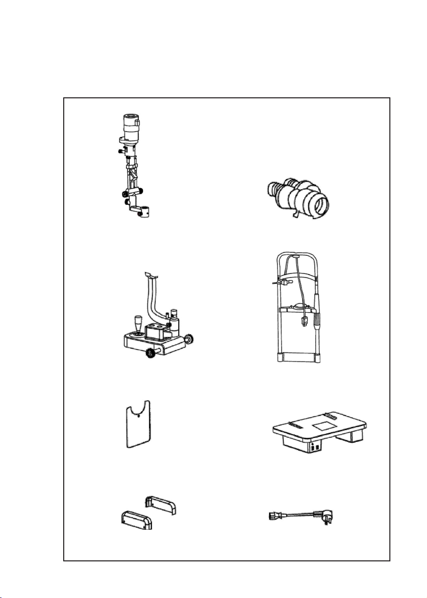
2.1 Components
A B
C D
E F
HG
8
I J K
L M N
PO Q
R TS
U V
X
W
9

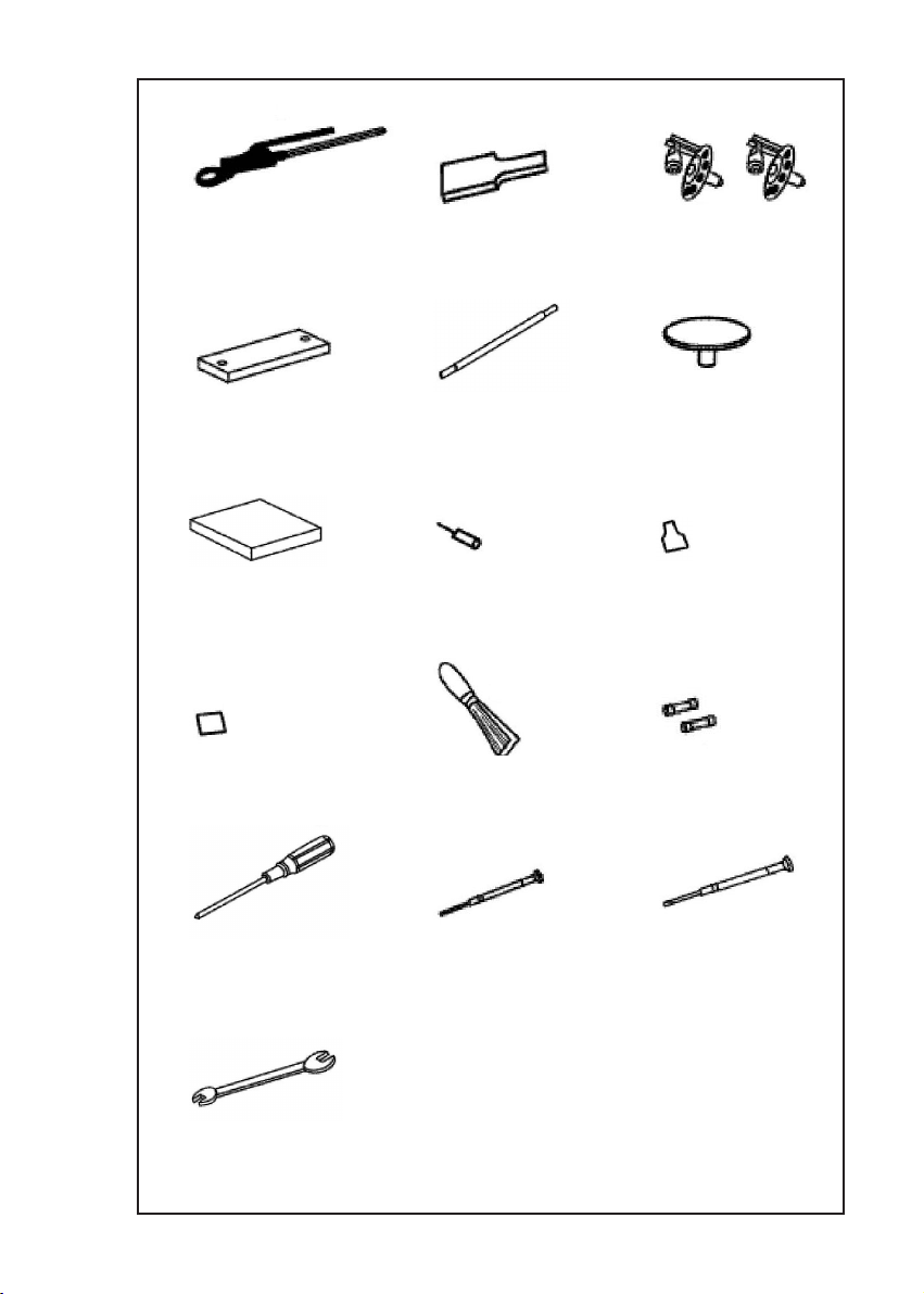
Name Quantity
A Illumination Part
B Microscope (with 10x eyepieces)
C Base Part
D Head-Rest Part
E Breath Shield
F Worktable with Power Box
G Rail Cover
H Input Power Cable
I Hruby Lens
J Hruby Lens Guide Plate
K Spare Main Illumination Bulb
L Chin-Rest Paper
M Focusing Test Rod
N Protection Cap
O Dust-Proof cover
P Fixation Target
Q Spare Long Reecting Mirror
R Spare Short Reecting Mirror
S Brush
T Spare Fuse
U Phillips Screw Driver with wood handle
V Watch Screw Driver (big)
W Watch Screw Driver (small)
X Spanner
1
1
1
1
1
2
1
1
1
2
1
1
1
1
1*
1
1
1
1
2
1
1
1
1
(*Optionally available in some region)
2.2 Assembly Procedure
Phillips Screwdriver with wood handle (U)
Watch screwdriver (V)
Wrench (X)
10
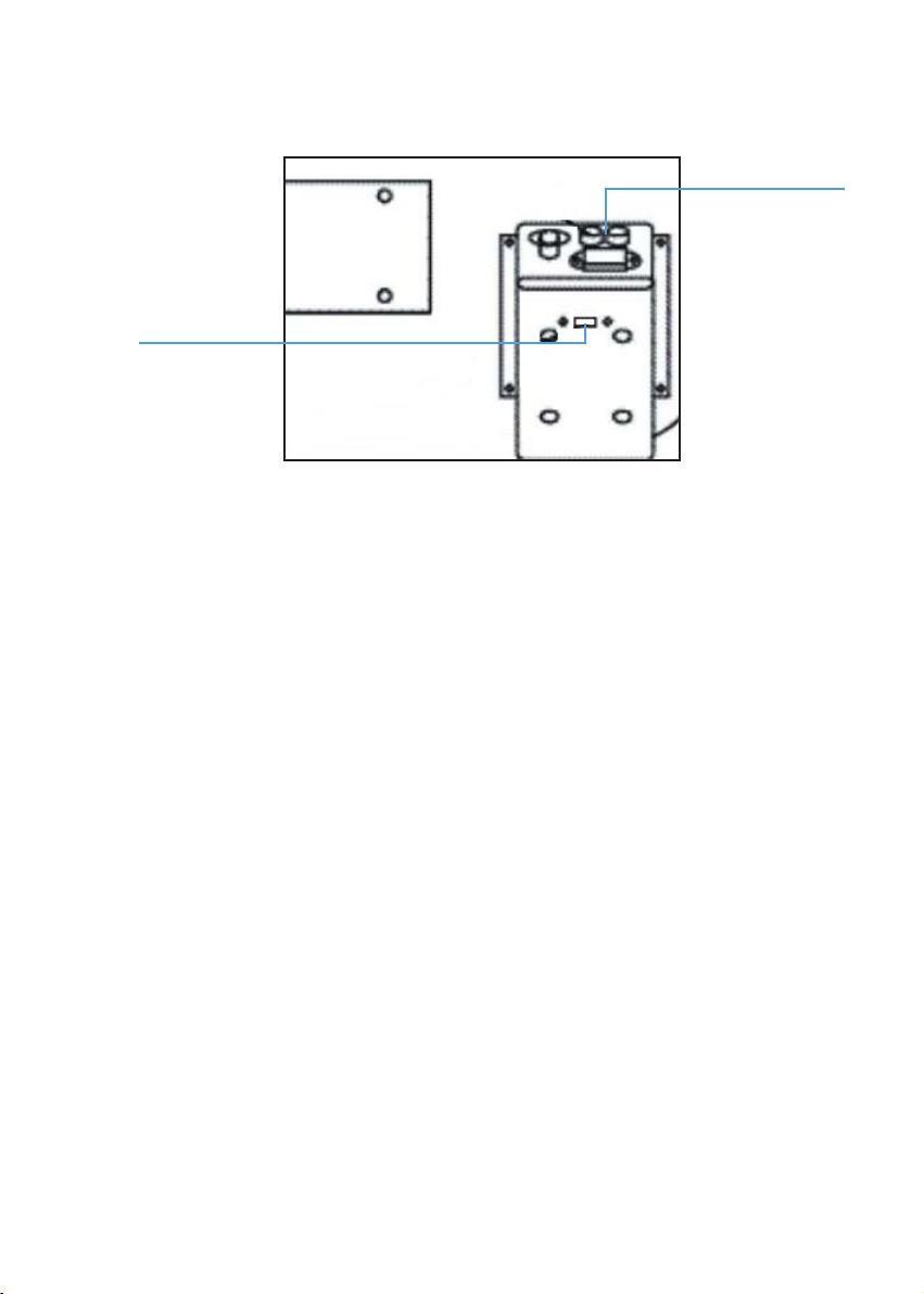
1. Selecting voltage and fuse
Fuse holder
Voltage
selector
Selector voltage and fuse
• Check the setting on the voltage selector located on the bottom of the power
box. If it doesn’t match with the input voltage, slide it to the proper position
with screwdriver (V).
• Open the fuse holder with screw driver (U) and take out the fuse, ensure that
its rated value corresponds to the mains voltage:
110 Volt.....................1A
220 Volt.....................0.5A
The 220 V- 0.5 A is installed by the factory.
Important Matters
Set the input voltage and frequency of the instrument according to that of the mains.
2. Assembling the worktable (F)
• To attach the worktable on the LSL1400 motorized instrument table, please
unscrew the four M8x20mm bolts with spring washers with the wrench (X).
• Align the worktable screw hole to the assembly hole of the instrument table.
11
• Place the worktable so that the power panel faces the user, then refasten
the bolt securely with the wrench.
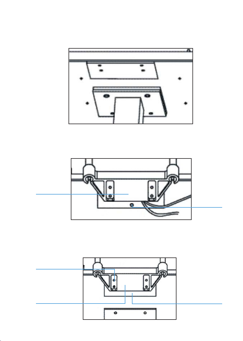
3. Assembling the Head-rest Part (D)
Head rest
xation plate
Chin rest
connection
board
• Remove the four screws attached to the chinrest connection board with the
screw driver (U).
Screw
Head rest
xation plate
connection board
Chin rest
12
• Put two cables in the gap between the headrest xation plate and the chin rest connection board.
• While ensuring the cables are not compressed, retighten the previously
removed screws.
4. Assembling the base part (C) and the rail covers (G)
Wheel
Rail
• Place the wheels of both sides of the base (C) on the rails on the worktable
• Check whether the wheels can be rolled smoothly on the rails.
• Remove the four screws attached to the rail with the screw driver (W).
• Place the rail cover (G) to the rail and retighten the previously removed screws.
Mark
Shaft sleave
Limiting board
13
5. Assembling Illumination part (A)
• Loosen the illumination arm bolt (13).
13
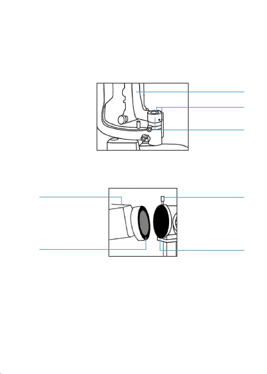
• Rotate the brass shaft sleeve to make the angle of the red mark and the
illumination arm between 30º and 90º.
• Loosen the screw on the illumination arm with the screwdriver (V). Align the
assembly hole of the illumination arm to the brass shaft sleeve and lower
carefully, while simultaneously aligning the two red marks.
Illumination arm
Mark
Screw
• After the two red marks are accurately aligned, retighten the screw.
B
6. Assembling the binocular tubes (B)
• Align the groove on the binocular tubes with the pin on the microscope body.
• Tighten the xing screw.
Fixing screw
PinGroove
14
7. Assembling the breath shield (E)
Important Matters
Avoid touching any lens surface while assembling the breath shield (E).
• Remove the breath shield xation screw from the microscope arm.
• Pass the removed screw through the hole of the breath shield then re-screw
it into the arm.
Microscope arm
Breath shield
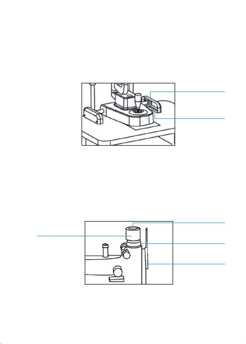
8. Removing the illumination part shipping pad
• This pad is used to protect the slit mechanism of the illumination part during
shipping.
• Remove the rubber band and gently pull the pad out.
Rubber band Pad
Fixing screw
15
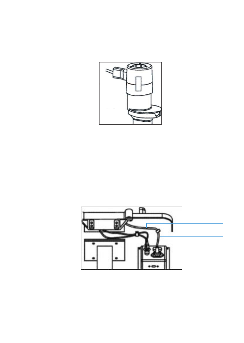
9. Connecting Plug
• Remove the sticky shipping tape from the cap. The tape ensures that the
cap is remains fastened to the lamp base during transportation.
Sticky tape
• Insert the plug on the top of the headrest part (D) into the socket of the lamp
cap (26) on the illumination part (A).
• Connect the two plugs below the headrest part with the corresponding output
sockets of the power box.
• Insert the plug of the input power cable (H) into the input socket of the power
box.
H
Cable clip
• Remove the cable clips from the bottom of the worktable with screwdriver
(U) and route the output and input cables through them, then re-attach them
to the bottom of the worktable.
16

10. Assemble the Hruby Lens (I)
• Insert the Hruby lens ( I ) into the Hruby lens holder (26) on the headrest part.
Be careful not to touch the lens surface.
• Place the Hruby lens guide plate (J) into the main shaft hole of the base part
with the small end pointed at the headrest part.
Hruby lens
holder
11. Assembling the chin-rest (E)
• Pull out the two xing pins from the chinrest.
I
J
• Remove and discard the packaging for the chin-rest paper and position the
paper.
• Insert the xing pins through the holes.
17
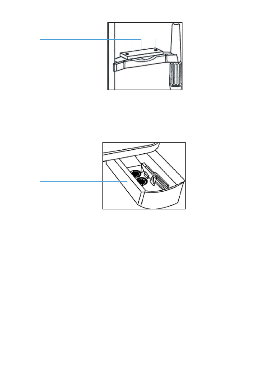
12. Storing spare parts
Spare parts may be stored in the accessory drawer.
6
PinH
2.3 Inspection procedure after assembly
1. Power plug
• This instrument supplied with a 3-wire grounded line cord. Do not remove
or disconnect the ground. Please select proper power sockets and plugs
• Always ensure that the instrument is well grounded.
Important Matters
Please use the special cable supplied with this instrument.
18
2. The power box and the illumination part
• When the main power switch (8) of the power box is placed at “1” it turns
on, and when located at “0” it turns off. The main power switch should be
set to the “0” position before connecting the input cable with the power
socket.
• Turn on the main power switch, and the pilot lamp (9) will illuminate.
Open the slit width control knob (35) to examine the illumination.
• Press the brightness control switch (7) in each of the two positions, the
brightness should be change accordingly.
• Check the xation target device to conrm it is lit.
• Check that all the movable parts such as aperture and slit height control knob
(29), lter selection lever (28), and magnication lever (18), etc. move freely.
• After inspection, turn off the main power and cover the instrument with the
dust cover (O).
3. Operation
3.1 Diopter compensation and pupillary distance adjustment.
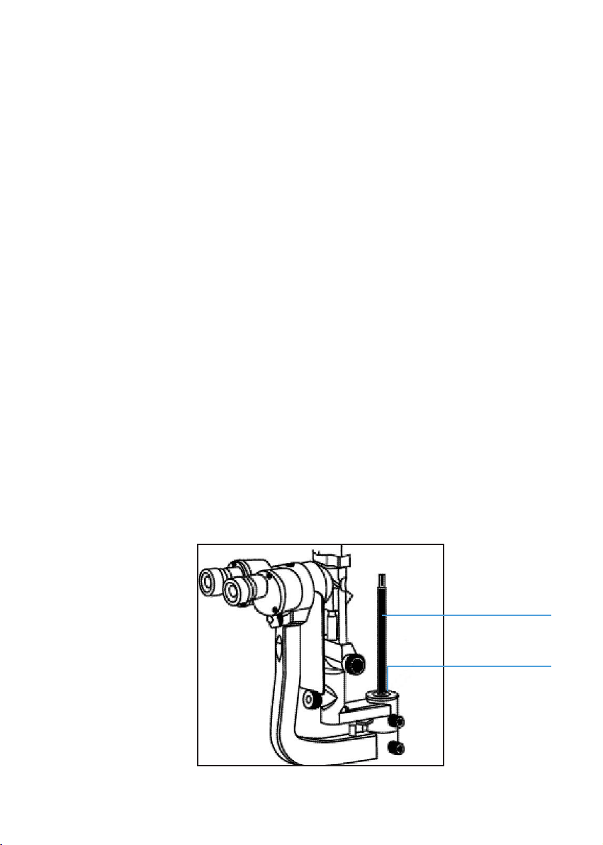
1. Use of the focusing test rod (M)
Focusing
test rod
Shaft holder
19

The focusing test rod is used to conrm that the microscope is adjusted correctly.
Insert it into the main shaft hole with the at surface facing the objective lens in
the direction of the user.
Important Matters
After adjustment, remember to remove the rod and insert the protective cap.
2. Brightness adjustment
Turn on the main power switch and set the brightness control switch (7) at
the “N” position. Turn the slit width control knob (35) to make the slit width
between 2 and 3mm.
3. Diopter compensation
The focus of the microscope is calibrated according to the emmetropia.
If the user is ametropic, he should adjust the eyepiece diopter.
Adjustment should be performed as follows:
• Rotate the diopter adjustment ring (19) counter clockwise until it stops.
• Rotate the ring clockwise until a sharp slit image appears on the focusing
test rod.
• Adjust the other eyepiece using the same procedure.
• Record the diopter value on each eyepiece for future reference.
Prism boxDiopter scale
Adjustment ring
20
4. Pupillary distance adjustment
Separate the prism boxes of the microscope with both hands to adjust the
pupillary distance until both eyes can stereoscopically see the same image
on the focusing test rod.
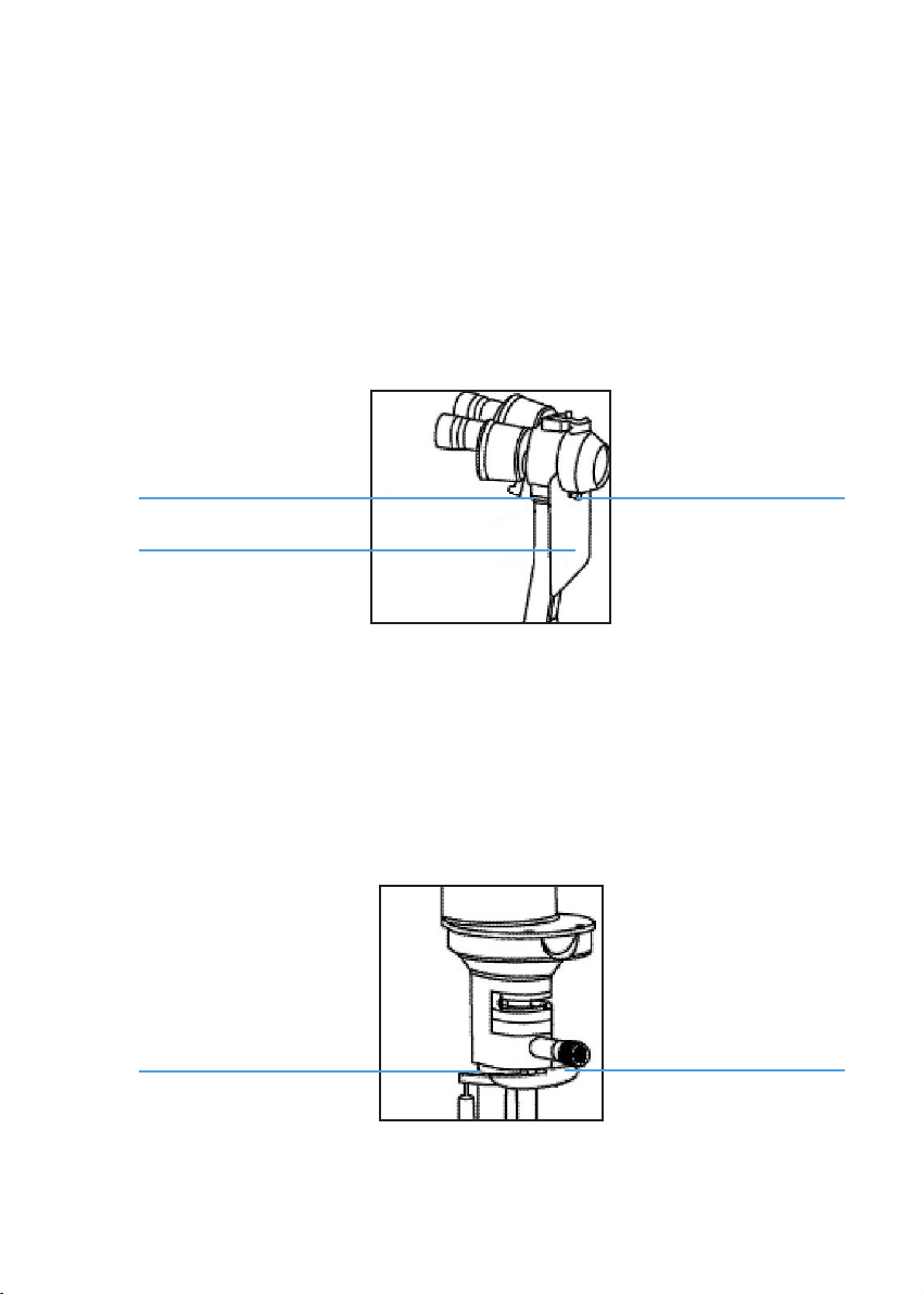
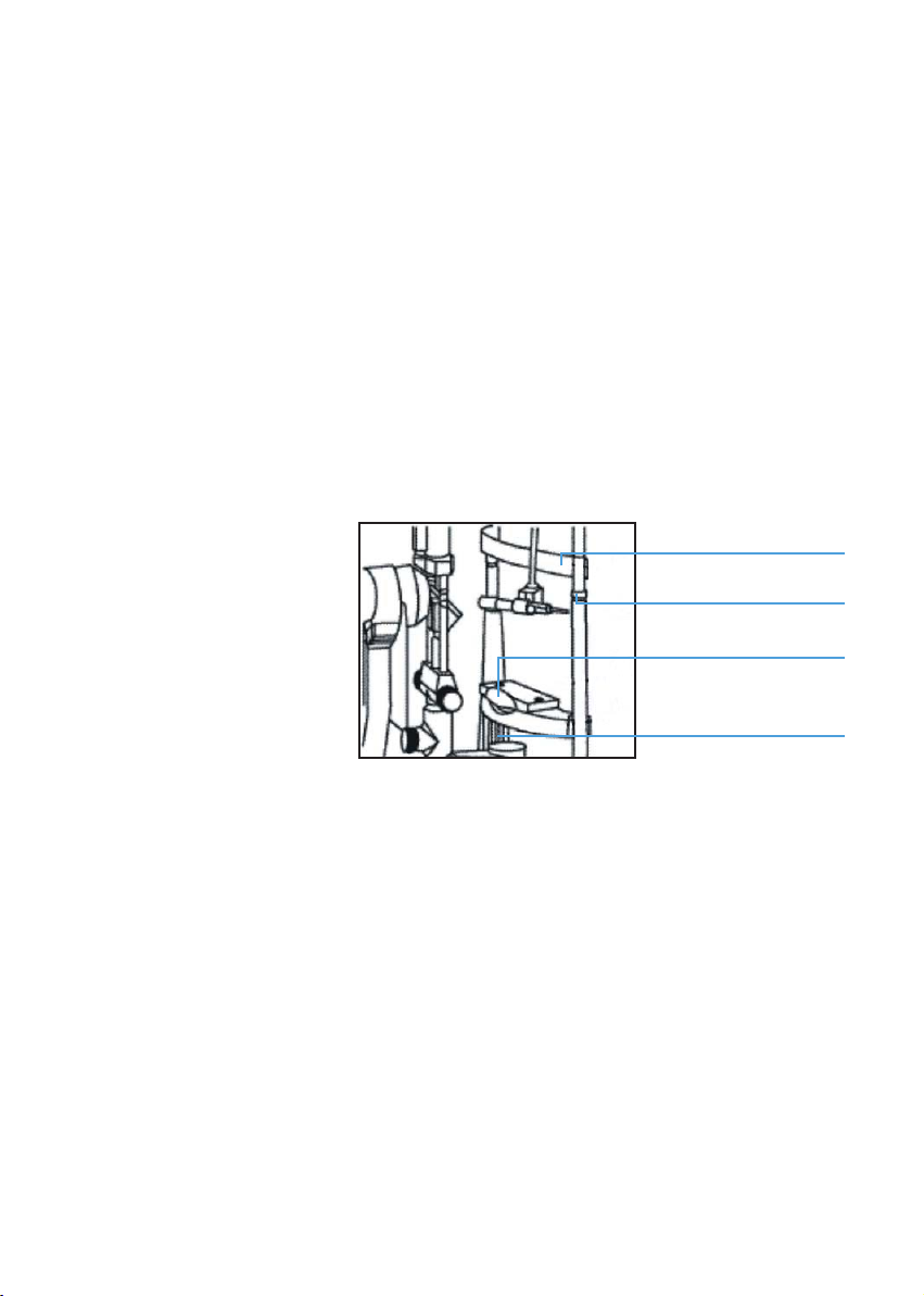
3.2 Patient position and xation target
1. Positioning the patient’s head
Have the patient place his chin on the chin-rest (17) and the forehead against
the forehead belt (24). Adjust the chin-rest elevation adjustment knob (12)
below the chin-rest until the patient’s canthus aligns with the horizontal
mark (23).
24
23
17
12
2. Use of the xation target
• Direct the patient to look at the xation target (30) with the eye not to be
examined. To change the xation position, move the lamp bar and curved
lever around the headrest.
• The xation target with diopter compensation supplies a dot and concentric
circles target. Slide the knob to adjust the diopter compensation from – 15D
to + 10 D.
21
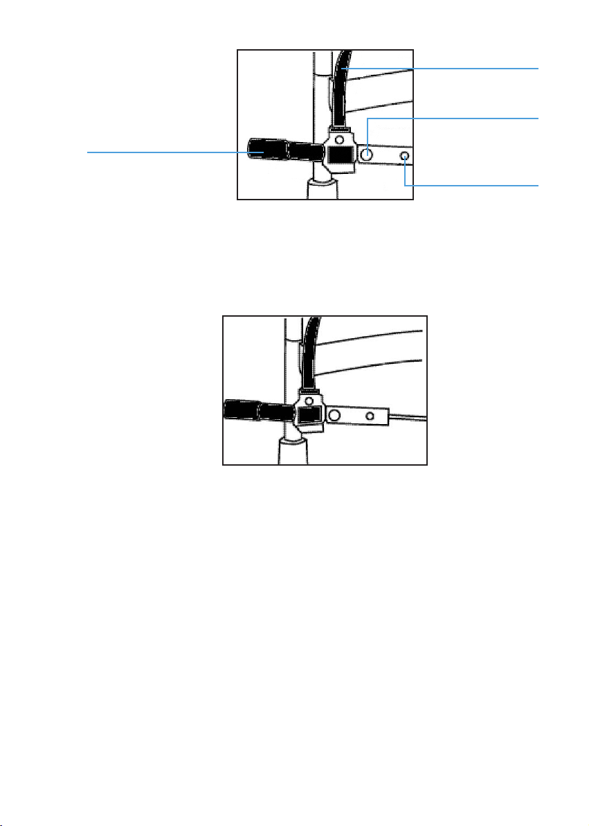
Curved level
Fixing screw
Fixaation target bar
Adjusting knob
The xation target with the spot light is intended for the patient whose diopter
exceeds – 15D. When changing, just loosen the xation screw, replace the xation
target with the spot light source and tighten the xation screw.
3.3 Base operation
1. Horizontal coarse adjustment
Keeping the joystick (1) straight up, move the base (4) to coarsely align the
microscope in the horizontal plane.
2. Vertical adjustment
Rotate the joystick to adjust the microscope’s height until it aligns with the
target. Turn the joystick clockwise to raise the microscope and counter
clockwise to lower it.
3. Horizontal ne adjustment
Tilt the joystick to make the microscope move slightly in the horizontal plan.
22

White watching through the eyepieces, tilt the joystick to align the microscope
at the object for a sharp image.
1
2
4
4. Locking the base
When nishing the adjustment, fasten the base locking screw (2) to lock the
base (4) and prevent it from sliding.
3.4 Illumination parts operation
1. Changing the slit width
Turn the slit width control knob (35) to adjust the slit width from 0 to 9mm.
The slit becomes a circle at the 9mm size.
Scale of slit width 35
2. Changing the aperture and slit height
Turn the aperture and slit height control knob (29) and 6 different circular
beams of light are available at full aperture: 9, 8, 5, 3, 1, 0.2mm diameters
23
 Loading...