

luxvision LM 300 User Manual
USER’S MANUAL
LENSMETER
LM 300

Notication
Dear Users,
Thank you for your purchase of LM 300 Lensmeter. Please take time to read our
user’s manual carefully before use.
This guarantees you to make full use of this unit and prolongs the operation life of
this unit.
Precautions
If you have detected abnormal heat, smoke, noise or smell, immediately stop using
the product.
In the event of an abnormality, turn off the power and disconnect the power plug from
the power socket. Continuing to use the product may result in electric shock or re.
Observe the instructions given below regarding the power cable:
• Be sure to use the supplied or specied power cable.
• Do not modify, forcibly bend, kink or pull the power cable.
• When disconnecting the power cable from the AC outlet, be sure to hold the cable
by the plug.
Pulling the cable may cause wire breakage or shot circuit, resulting in re or
electric shock.
• Do not connect or disconnect the plug of the power cable to/from the AC outlet
using wet hands.
Doing so may result in electric shock.
• Do not touch the product with wet hands while the power cable is connected
to the AC outlet.
Doing so may result in electric shock.
• If the product will not be used for a long period, disconnect the power cable from
the power source. Leaving the cable connected to the power socket for a prolonged
period will consume electricity and may result in heating.

Content
1. Function Introduction .....................................................................................4
2. Working Principle Device ................................................................................4
3. Functions ......................................................................................................5
4. Operation ......................................................................................................8
5. Maintenance ................................................................................................18
6. Common Trouble Shooting ...........................................................................19
7. Specications ..............................................................................................20
1. Function Introduction
This device is divided into two models, A and B, in which A is standard model
and B is strengthened model with prism compensator.
In the following description, all sections or content marked with “*” before them are
specialized content of model B device.
Optic, machine and microelectronic integrated technologies are adopted in this device,
where, yellow liquid crystal display is available to achieve stable and precise measuring
result, proven to be an ideal device for having one’s eyesight tested for spectacles.
This device is applicable to all level measurement testing departments, spectacles
manufacturers, spectacles retail stores, hospital’s department of ophthalmology
and optical elements factories for conducting measurement of spherical lens diopter
of spectacles or lens, diopter of cylindrical lens, astigmatism axis angle of cylindrical
lens, diopter of bifocal lens, prism degree and prism basal angle.
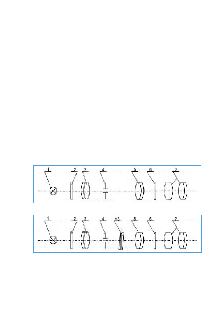
2. Working Principle of Device
Fig. 1 Drawing of Optical Principle for Model A
Fig. 2 Drawing of Optical Principle for Model B
1. Light source 2. Mark Dividing Plate 3. Measurement Objective
4. Diaphragm 5. Telescopic Objective 6. Eyepiece Dividing Plate
7. Eyepiece Set *8. Prism Compensator
4
This device consists of a coaxal optic system. Light sent forth from 1-Light Source
(LED) lights up 2-Mark Dividing Plate. After passing though 3-Measurement Objective
and 5-Telescopic Objective, 2-Mark Dividing Plate is imaged at position of 6-Eyepiece
Dividing Plate. At this time, through 7-Eyepiece Set, the distinct reticule images of
2-Mark Dividing Plate and 6-Eyepiece Dividing Plate can be seen.
During operation, put spectacle lens at the place of 4-Diaphragm (measurement
bearing scat), and turn diopter measuring hand-wheel and astigmatism turning handwheel so that distinct image of 2-Mark Dividing Plate is obtained. Now, the number
showing on the liquid crystal display screen is just the diopter value of this lens.
3. Functions
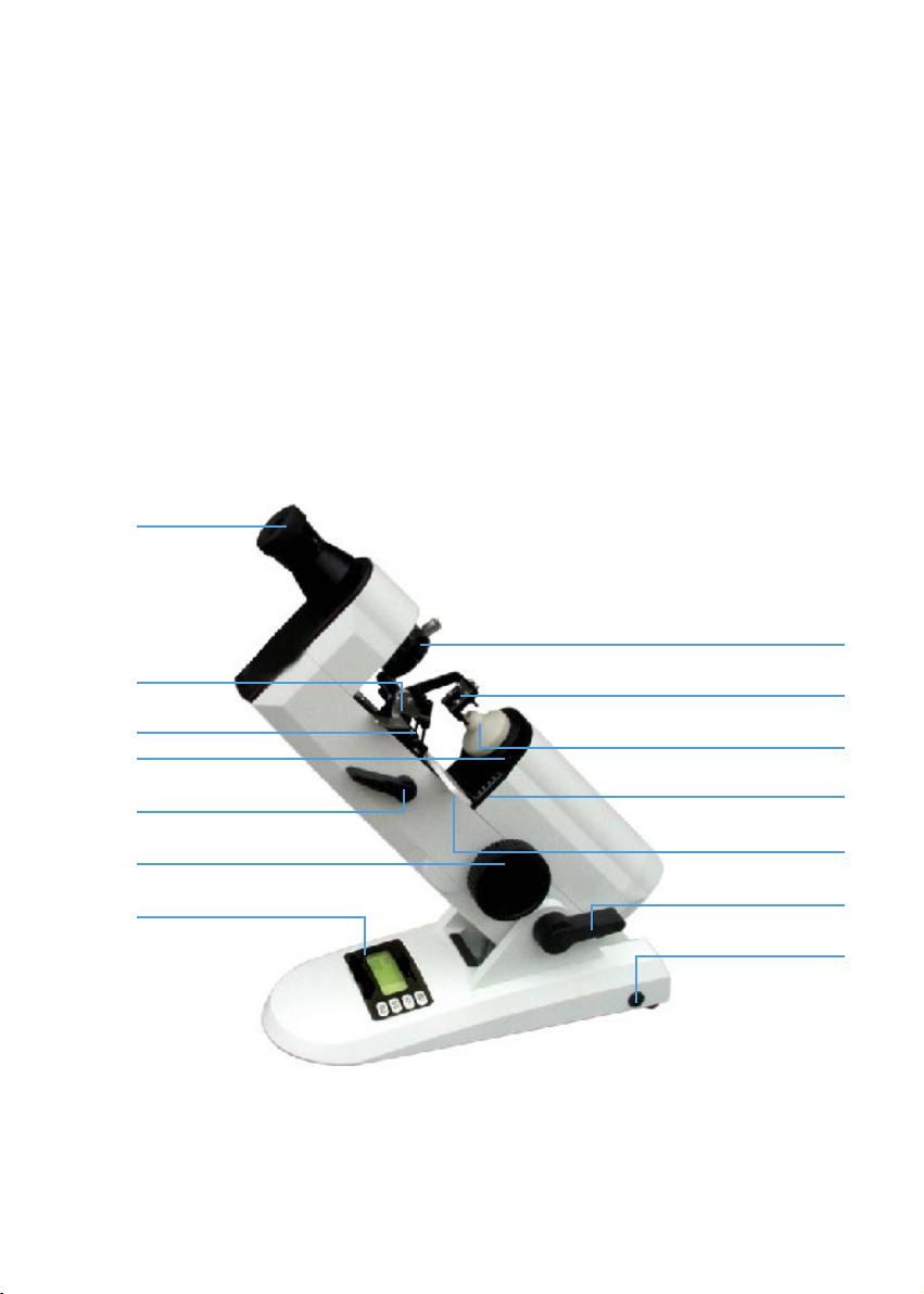
3.1 Main View (Fig3)
1
2
10
11
5
12
13
14
3
4
7
6
8
9
Fig. 3
5

1. Eyepiece
Eyepiece part is a screw type focusing unit with focusing range of ±5D,
adaptable to different eye-sights of human eyes.
*2. Prism Compensator
It is used to measure prism lens with prism degree bigger than 5∆.
3. Lens Pressing Mechanism
3 plastic pressing feet equipped with spring are used to press lens, able to
stably press lens with any shape of surface, with no damage to lens surface.
4. Measurement Bearing Seal
It can hold lens with any shape of surface with no damage to lens surface.
5. Astigmatism Turning Hand-Wheel
It is used to measure and locate astigmatism axis angle of cylindrical lens
and basal angle of prism lens.
6. Lens Pushing Board
When lens on the lens frame is conducted, lower part of lens frame (i.e. two
lens rings) shall contact the lens pushing board.
7. Diameter Indication Measuring Scale
When lens pushing board contacts edge of lens, it is possible to read lens
diameter.
8. Inclining Angle Adjusting Handle of Device
It is able to enable measurement user to adjust inclining angle of the device
easily, who can work with a comfortable posture. By rotating backwards
the adjusting handle, measurement user may tilt me device to a proper angle
according to specic status of work table, then simply lock up the handle.
9. Power Supply Socket
10. Dot-Making Mechanism
This mechanism consists of 3 identical dot-making pens connected into
a line, where, one in the middle is used to mark lens center, and connected
line of marking dots of 3 pens is used to mark astigmatism axis angle of lens
and basal angle of prism lens.
11. InkpadBox
It is used to store inkpad or ink for print.
6

12. Lens Pushing Hand Lever
It is used to move lens pushing board back and forth.
13. Diopter Measuring Hand-wheel
3.2 Drone and Eyepiece Dividing Plate (Fig.4)
Round-dot drone
Cross-line drone
Fig. 4
14. Liquid Crystal Display Screen
It displays diopter value of the measured lens.
15
16
15. Eyepiece Dividing Plate
Prism degree measuring scale and calibrated dial are marked on it. Prism
degree is marked with space of 1∆, where, integral prism degree is read
directly on the measuring scale, and decimal prism degree is read by
estimation from measuring scale. Calibrated dial 0 ~ 180° is marked with
space of 1°, and 180º ~ 360° with space of 5°.
16. Drone
Distinct image of mark dividing plate involves round-dot drone and cross-line
drone.
7
 Loading...