

Page 1

Artisan Technology Group is your source for quality
new and certied-used/pre-owned equipment
• FAST SHIPPING AND
DELIVERY
• TENS OF THOUSANDS OF
IN-STOCK ITEMS
• EQUIPMENT DEMOS
• HUNDREDS OF
MANUFACTURERS
SUPPORTED
• LEASING/MONTHLY
RENTALS
• ITAR CERTIFIED
SECURE ASSET SOLUTIONS
SERVICE CENTER REPAIRS
Experienced engineers and technicians on staff
at our full-service, in-house repair center
Instra
Remotely inspect equipment before purchasing with
our interactive website at www.instraview.com
Contact us: (888) 88-SOURCE | [email protected] | www.artisantg.com
SM
REMOTE INSPECTION
View
WE BUY USED EQUIPMENT
Sell your excess, underutilized, and idle used equipment
We also offer credit for buy-backs and trade-ins
www.artisantg.com/WeBuyEquipment
LOOKING FOR MORE INFORMATION?
Visit us on the web at www.artisantg.com for more
information on price quotations, drivers, technical
specications, manuals, and documentation
Page 2

FOT Lab Kit Fluoroptic
Thermometer
User’s Manual
For firmware version 2.80 and higher
Artisan Technology Group - Quality Instrumentation ... Guaranteed | (888) 88-SOURCE | www.artisantg.com
Page 3

Confidential Information
The material contained herein consists of information that is the property of LUXTRON
Corporation and intended solely for use by the purchaser of the equipment described in
this manual. All specifications are subject to change without notice. Changes are made
periodically to the information in this publication, and these changes will be incorporated
in new editions.
LUXTRON Corporation prohibits the duplication of any portion of this manual or the use
thereof for any purpose other than the operation or maintenance of the equipment
described in this manual, without the express written permission of LUXTRON
Corporation.
Copyright
© LUXTRON Corporation 2003-2005. All rights reserved.
Trademarks
LUXTRON, Fluoroptic, and the LUXTRON logo are registered trademarks
and TrueTemp is a trademark of LUXTRON Corporation.
All other trademarks are trademarks, registered trademarks, and/or service marks of their
respective holders.
LUXTRON Corporation
3033 Scott Blvd.
Santa Clara, CA 95054-3316
Telephone (408) 727-1600
FAX (408) 727-1677
E-mail [email protected]
Website http://www.luxtron.com
Part Number: 38-13745-01
Revision E
November 2005
Artisan Technology Group - Quality Instrumentation ... Guaranteed | (888) 88-SOURCE | www.artisantg.com
Page 4

Contents
Preface
1 Introduction
FOT Lab Kit Contents . . . . . . . . . . . . . . . . . . . . . . . . . . . . . . . . . . . . . . . . . . . . 1-2
System Overview . . . . . . . . . . . . . . . . . . . . . . . . . . . . . . . . . . . . . . . . . . . . . . . 1-3
Fluoroptic
2 System Components
®
Technology Overview. . . . . . . . . . . . . . . . . . . . . . . . . . . . . . . . . 1-5
Probes . . . . . . . . . . . . . . . . . . . . . . . . . . . . . . . . . . . . . . . . . . . . . . . . . . . . . . . . 2-2
Standard Options and Accessories. . . . . . . . . . . . . . . . . . . . . . . . . . . . . . . . 2-4
3 System Operation
Getting Started . . . . . . . . . . . . . . . . . . . . . . . . . . . . . . . . . . . . . . . . . . . . . . . . 3-1
4 User Interface Commands
Parameter Commands (Two-Letter) . . . . . . . . . . . . . . . . . . . . . . . . . . . . . . . 4-2
Action Commands (One-Letter) . . . . . . . . . . . . . . . . . . . . . . . . . . . . . . . . . 4-25
5 Temperature Data Reporting
RS-232 Serial Interface Data Format . . . . . . . . . . . . . . . . . . . . . . . . . . . . . . . 5-1
A Calibration Procedure
Digital Temperature Output Calibration Procedure . . . . . . . . . . . . . . . . . . A-1
Calibration Instructions . . . . . . . . . . . . . . . . . . . . . . . . . . . . . . . . . . . . . . . . . . A-3
Analog Temperature Output Calibration . . . . . . . . . . . . . . . . . . . . . . . . . . . A-7
FOT Lab Kit User’s Manual i
Artisan Technology Group - Quality Instrumentation ... Guaranteed | (888) 88-SOURCE | www.artisantg.com
Page 5

Contents
B Warranty and Service
Limited Warranty . . . . . . . . . . . . . . . . . . . . . . . . . . . . . . . . . . . . . . . . . . . . . . . B-1
Damage In Shipment for the Original Purchaser . . . . . . . . . . . . . . . . . . . . . B-2
What to do in Case of a Malfunction . . . . . . . . . . . . . . . . . . . . . . . . . . . . . . B-2
Shipments to LUXTRON for Repair. . . . . . . . . . . . . . . . . . . . . . . . . . . . . . . . . . B-2
Shipping Address:. . . . . . . . . . . . . . . . . . . . . . . . . . . . . . . . . . . . . . . . . . . . . . . B-2
ii FOT Lab Kit User’s Manual
Artisan Technology Group - Quality Instrumentation ... Guaranteed | (888) 88-SOURCE | www.artisantg.com
Page 6

Figures
Figure 1-1 FOT Lab Kit Instrument . . . . . . . . . . . . . . . . . . . . . . . . . . . . . . . . . . . . . . 1-2
Figure 1-2 Fluoroptic
Probes, and Optional Accessories. . . . . . . . . . . . . . . . . . . . . . . . . . . . 1-3
Figure 1-3 Plot Representation of LUXTRON’s Fluoroptic
Technique . . . . . . . . . . . . . . . . . . . . . . . . . . . . . . . . . . . . . . . . . . . . . . . 1-5
Figure 2-1 Standard Probes for Use with FOT Lab Kit . . . . . . . . . . . . . . . . . . . . . . 2-2
Figure 3-1 Connecting the FOT Lab Kit Components . . . . . . . . . . . . . . . . . . . . . 3-2
Figure 4-1 Sampling Report . . . . . . . . . . . . . . . . . . . . . . . . . . . . . . . . . . . . . . . . . 4-19
®
Thermometry System Includes an Instrument,
®
Thermometry
Biomedical Lab Kit User’s Manual iii
Artisan Technology Group - Quality Instrumentation ... Guaranteed | (888) 88-SOURCE | www.artisantg.com
Page 7

Figures
iv Biomedical Lab Kit User’s Manual
Artisan Technology Group - Quality Instrumentation ... Guaranteed | (888) 88-SOURCE | www.artisantg.com
Page 8

Tables
Table 1-1 FOT Lab Kit Performance Specifications . . . . . . . . . . . . . . . . . . . . . . 1-6
Table 2-1 Standard Accessories for Use with FOT Lab Kit . . . . . . . . . . . . . . . . . 2-4
Table 3-1 List of Correct Lookup Tables for Various Probe Types . . . . . . . . . . . 3-3
Table 4-1 Summary Listing of Parameter Commands . . . . . . . . . . . . . . . . . . . 4-5
Table 4-2 Summary Listing of Action Commands . . . . . . . . . . . . . . . . . . . . . . . 4-5
FOT Lab Kit Fluoroptic Thermometer Users Manual v
Artisan Technology Group - Quality Instrumentation ... Guaranteed | (888) 88-SOURCE | www.artisantg.com
Page 9

Table s
vi FOT Lab Kit Fluoroptic Thermometer Users Manual
Artisan Technology Group - Quality Instrumentation ... Guaranteed | (888) 88-SOURCE | www.artisantg.com
Page 10

Preface
This document describes the FOT Lab Kit Fluoroptic® thermometer
and is organized into the following sections.
■ Chapter 1, “Introduction’’, provides an overview of the
LUXTRON FOT Lab Kit and Luxtron’s Fluoroptic® technology.
■ Chapter 2, “System Components’’, describes the various parts
and components that make up a complete Fluoroptic®
thermometry system.
■ Chapter 3, “System Operation’’, provides general instructions
on how to operate and use the FOT Lab Kit.
■ Chapter 4, “User Interface Commands’’, provides a detailed
description of all user interface commands and user selectable
parameters.
■ Chapter 5, “Temperature Data Reporting’’, describes the type
and format of data reported by the instrument.
■ Appendix A, “Calibration Procedure’’, describes the procedure
used to calibrate the instrument.
■ Appendix B, “Warranty and Service’’, provides warranty and
service information.
FOT Lab Kit User’s Manual Preface-i
Artisan Technology Group - Quality Instrumentation ... Guaranteed | (888) 88-SOURCE | www.artisantg.com
Page 11

Preface
Preface-ii FOT Lab Kit User’s Manual
Artisan Technology Group - Quality Instrumentation ... Guaranteed | (888) 88-SOURCE | www.artisantg.com
Page 12

1 Introduction
The FOT Lab Kit is a fiber optic thermometry system that allows
users to measure temperature where conventional sensors fail.
Luxtron’s unique technology, called Fluoroptic® Thermometry
(FOT), offers probes that are totally immune to electromagnetic
interference (EMI) and of entirely non-metallic construction. These
qualities make FOT probes perfectly suited for measuring
temperatures in harsh environments, such as high voltages and
strong radio frequencies (RF), often encountered during research or
in industrial processes.
Applications include:
■ Medical treatment and research
MRI, microwave, laser, hyperthermia, RF ablation, cryogenic
treatments
■ Semiconductor equipment
Electrostatic chucks, etch and deposition chambers, Rapid
Thermal Process chambers
■ Industrial applications
RF and microwave drying, and harsh chemistries
■ Utility equipment
Transformer windings and high voltage transmission lines
FOT Lab Kit User’s Manual 1-1
Artisan Technology Group - Quality Instrumentation ... Guaranteed | (888) 88-SOURCE | www.artisantg.com
Page 13
Introduction
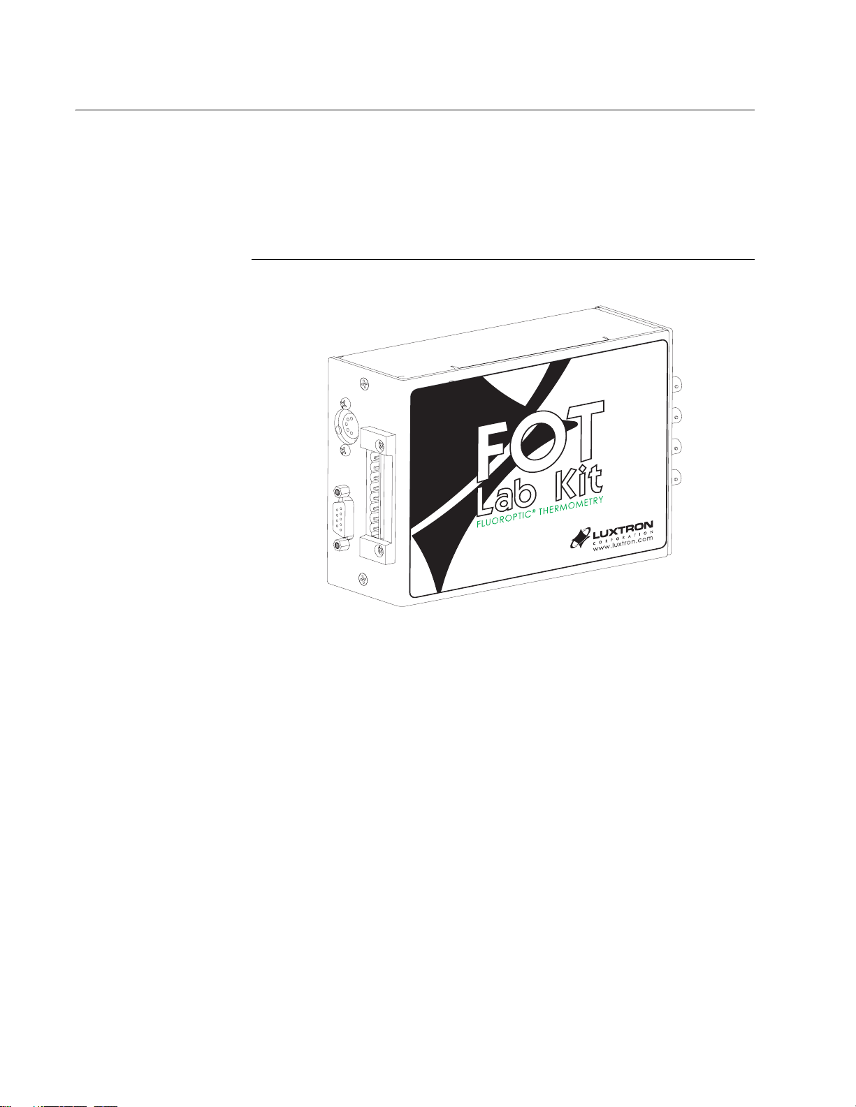
FOT Lab Kit Contents
The FOT Lab Kit includes a four-channel Fluoroptic® thermometry
instrument shielded in a rugged steel enclosure, a universal power
supply, an RS-232 cable, and a user’s manual; all within a compact
carrying case.
Figure 1-1 FOT Lab Kit Instrument
The FOT Lab Kit Instrument uses an RS-232 serial interface for
command input and data output. The unit communicates at 9,600
bps using an 8-N-1 data format. In addition, it includes a 0-10 volt
analog output for each measurement channel.
The user interface may be accessed through standard terminal
emulation software e.g. HyperTerminal, ProComm Plus, etc.
through a customer-supplied control application, or through
LUXTRON’s Windows
®
-based TrueTemp
TM
software. Compatible
with Windows® 95/98, Windows® NT or higher, the TrueTempTM
software offers full-featured data acquisition, graphing, and analysis.
1-2 FOT Lab Kit User’s Manual
Artisan Technology Group - Quality Instrumentation ... Guaranteed | (888) 88-SOURCE | www.artisantg.com
Page 14
System Overview
Introduction
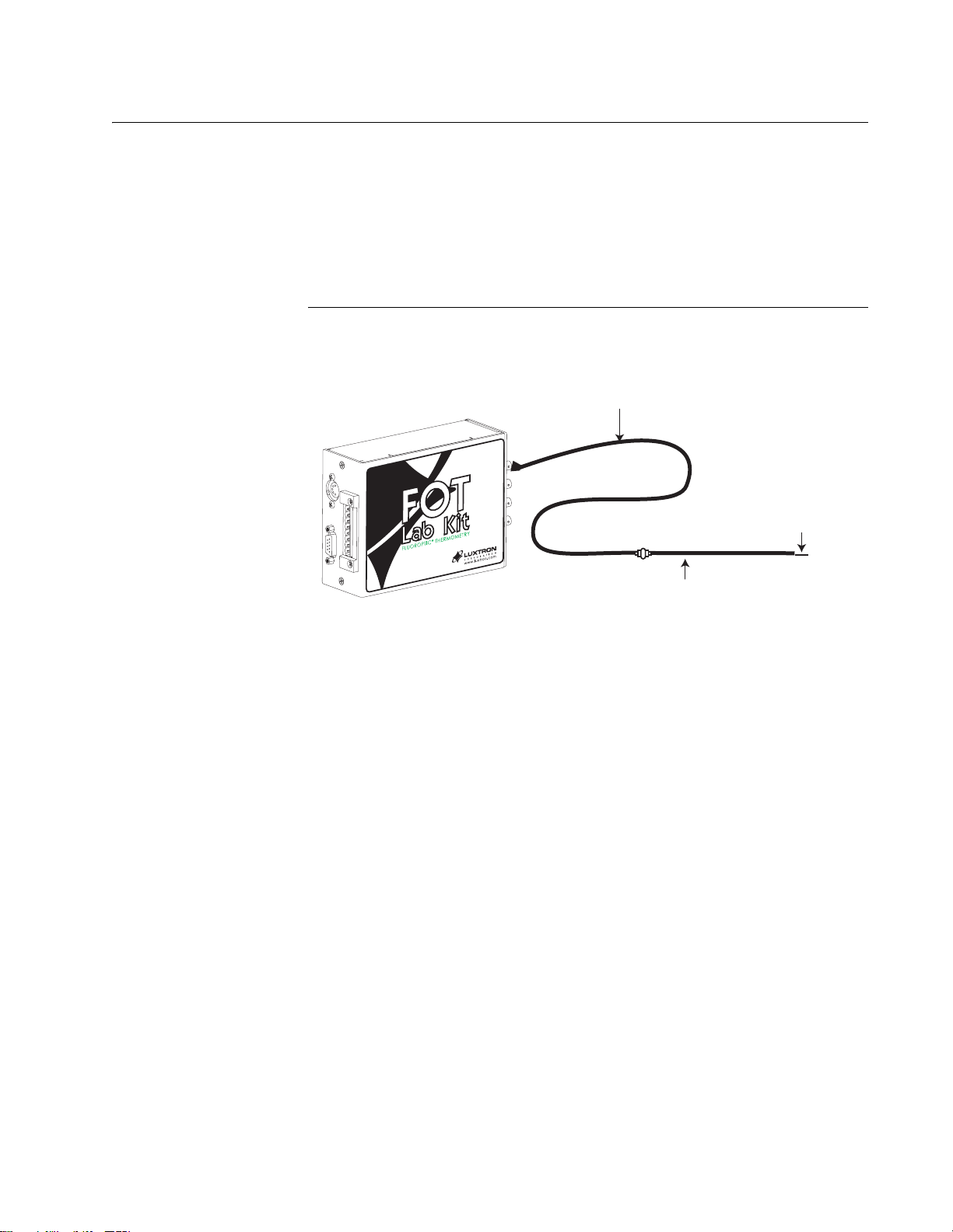
A complete FOT system consists of an instrument and probe.
Optional accessories include fiber optic extension cables, vacuum
feedthroughs, and PC acquisition and graphing software (see Figure
1-2).
Figure 1-2 Fluoroptic® Thermometry System Includes an
Instrument, Probes, and Optional Accessories.
Fiber Optic
Extension Cable
(optional)
Fluoroptic Sensor
Luxtron Fluoroptic Probe
Instrument
The FOT Lab Kit Instrument is a four channel system that includes
0 to 10V analog outputs for each channel as well as an RS-232
interface.
Probes
Luxtron offers standard fiber optic probes for use with the FOT Lab
Kit. The probes are designed to suite a variety of applications.
Some are designed to measure the bulk temperature of an object
(immersion probes) while other are designed to measure the
surface temperature of an object (surface and non-contact probes).
These probes are available in standard lengths of 2, 5, and 10 meters
(see Figure 2-1, on page 2-2 for details).
LUXTRON specializes in developing custom probes to meet the
unique circumstances of OEM applications. Non-metallic and
®
electrically non-conductive, the Fluoroptic
probes are immune to
EMI and high voltages that adversely affect conventional sensors
FOT Lab Kit User’s Manual 1-3
Artisan Technology Group - Quality Instrumentation ... Guaranteed | (888) 88-SOURCE | www.artisantg.com
Page 15

Introduction
such as thermocouples, RTDs and thermistors. Call a LUXTRON
applications engineer to discuss development of a custom probe for
your specific OEM application. To see examples of custom probes,
visit LUXTRON’s website at www.luxtron.com.
Accessories
The most common accessory is a fiber optic extension. The
extension allows flexible mounting or locating of the instrument
with respect to the point of measurement. Standard extension
lengths are available in 2, 5, and 10 meters.
The other category of accessories is vacuum feedthroughs. These
allow either a probe or a fiber optic extension to enter vacuum
chambers through NPT fittings or ConflatTM flanges.
1-4 FOT Lab Kit User’s Manual
Artisan Technology Group - Quality Instrumentation ... Guaranteed | (888) 88-SOURCE | www.artisantg.com
Page 16
Fluoroptic® Technology Overview
The FOT Lab Kit uses LUXTRON’s patented Fluoroptic® technology,
based on a temperature sensitive phosphorescent sensor attached
to the end of an optical fiber. Pulses of light transmitted down the
fiber optic probe cause the sensor to be excited and fluoresce. The
DSP-based electronics of the FOT Lab Kit Instrument detect and
calculate the decay time of this fluorescence after each pulse. This
decay time varies precisely with the temperature of the sensor,
providing the basis for accurate temperature measurement. The
FOT Lab Kit Instrument achieves accuracy better than 0.5 oC and a
measurement range of -100 to +330 oC.
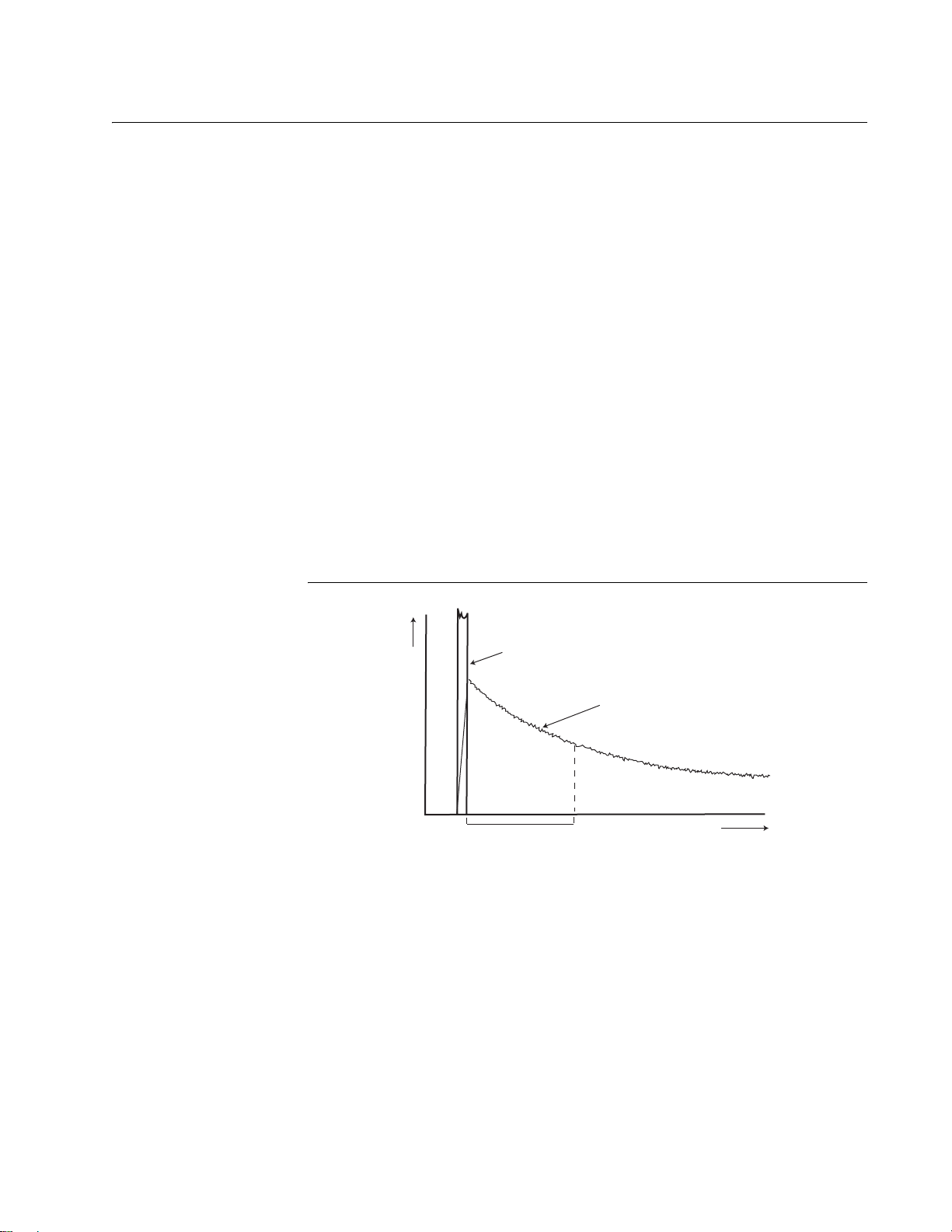
Below is a plot representation of the method used to extract the
florescence decay time (τ) of the phosphor sensor. A mathematical
curve fit correlates individual data points with stored values of (τ).
The measured value of (τ) is then conditioned with the values in a
calibration table to determine temperature.
Introduction
Figure 1-3 Plot Representation of LUXTRON’s Fluoroptic®
Thermometry Technique
Excitation
Light Pulse
Intensity
τ
Fluorescent
Signal
Time
FOT Lab Kit User’s Manual 1-5
Artisan Technology Group - Quality Instrumentation ... Guaranteed | (888) 88-SOURCE | www.artisantg.com
Page 17

Introduction
Table 1-1 FOT Lab Kit Performance Specifications
Number of Channels 4
Temperature Range -100 through +330
o
C, depending upon probe specification
Electrical Interference Probes are immune to EMI and RF
Accuracy
Uncalibrated 1% of full scale
Calibrated ±0.5
Repeatability ±0.5
o
C within ±50 oC of calibration
o
C RMS at 8 samples per measurement
Temperature Resolution
RS-232 Output 0.01
Analog Output 0.01
Short Term Drift <0.2
Long Term Drift <0.5
Output Format
o
C
o
C
o
C / hour
o
C / 10 days
o
K, oC, oF (user selectable)
Self diagnosis and probe error indications available through RS-232
Self-diagnostic
interface
Input Power Universal power supply
Serial Output RS-232 serial interface at 9,600 bps, N-8-1, no handshake
Analog Output 0.0 - 10.0VDC
Dimensions 184mm x 144mm x 51mm
Storage Temperature -55 to +75
Operating Temperature 10 to 50
o
C
o
C
Maximum Humidity 80%, non-condensing
1-6 FOT Lab Kit User’s Manual
Artisan Technology Group - Quality Instrumentation ... Guaranteed | (888) 88-SOURCE | www.artisantg.com
Page 18

2 System Components
The FOT Lab Kit is designed to function with a variety of standard
probes and accessories produced by LUXTRON Corporation. The
various probes are designed for different applications and are
described in Figure 2-1, “Standard Probes for Use with FOT Lab Kit,”
on page 2-2. Visit LUXTRON’s website or contact the LUXTRON
Sales Department for more detailed information.
FOT Lab Kit User’s Manual 2-1
Artisan Technology Group - Quality Instrumentation ... Guaranteed | (888) 88-SOURCE | www.artisantg.com
Page 19
System Components
Probes
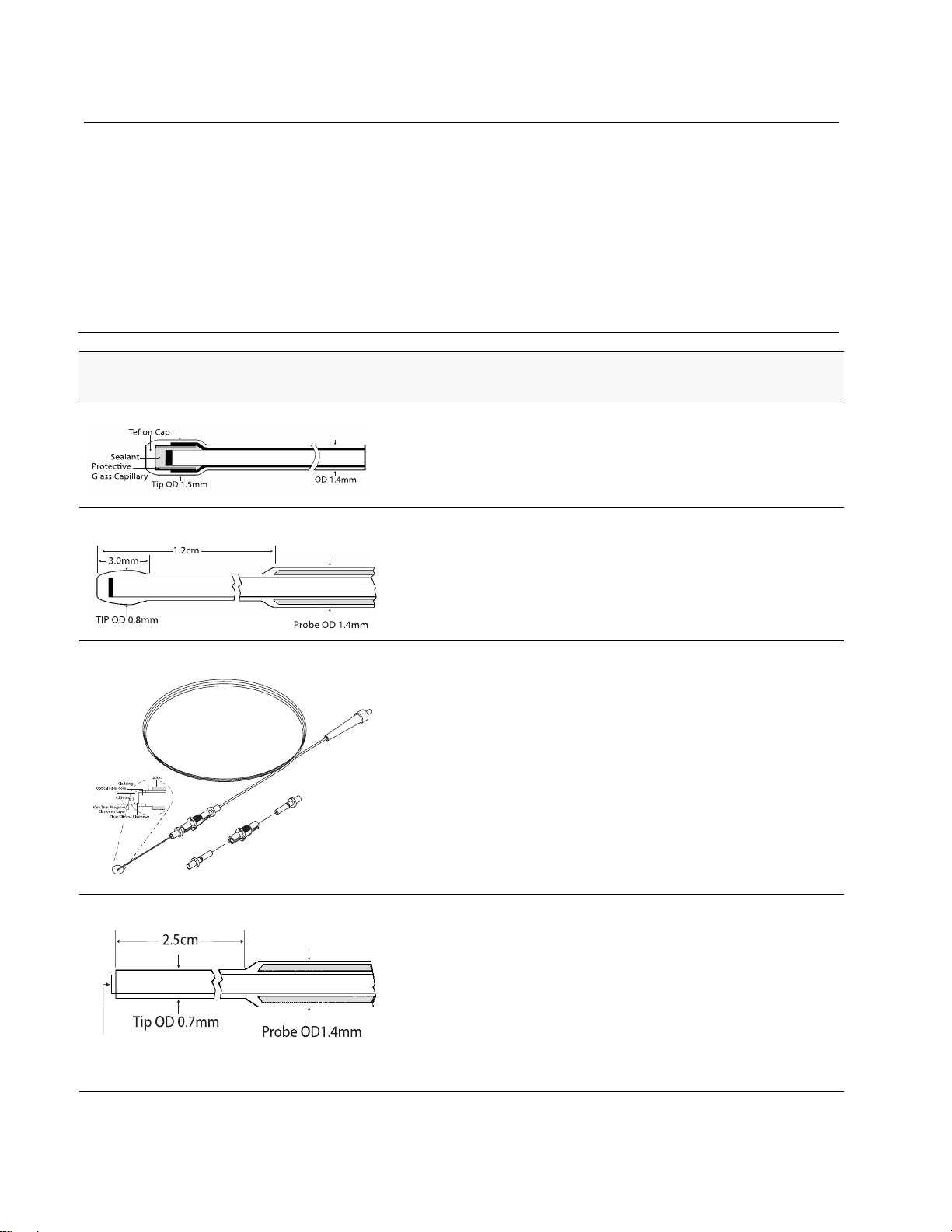
Standard Probes Fluoroptic probes are non-metallic and immune to EMI and radio-
frequency noise. The standard probes generally consist of a fiberoptic cable with LUXTRON’s temperature sensitive phosphor affixed
to the probing end and a fiber optic ST-style connector on the other
end for connection to the FOT Lab Kit.
Figure 2-1 Standard Probes for Use with FOT Lab Kit
Luxtron Part
Picture Description
Number
STM Probe
Application: General Purpose Immersion
Temp Range: 0 to 250
Response Time: 5s in still air
0.7s in stirred water
STF Probe
Application: Fast Response Immersion
Temp Range: 0 to 295
Response Time: 1.25s in still air
0.25s in stirred water
STS Probe
Application: Surface Contact
Temp Range: -25 to 200
Response Time: 25ms
o
C
o
C
o
C
00-13244-XX
00-13737-XX
00-13738-XX
Probe tip is a polished,
open end fiber
STR Probe Kit
Application: Non-contact Remote
Temp Range: -25 to 330
Includes:
0.1 gm Luxtron’s Alpha phosphor sensor powder
1mL 150
1mL 250
1mL 450
2m STP probe blank (see image at left)
Remote Sensing User’s Guide
o
C silicon binder
o
C silicon binder
o
C silicon binder
o
C
06-13740-01
2-2 FOT Lab Kit User’s Manual
Artisan Technology Group - Quality Instrumentation ... Guaranteed | (888) 88-SOURCE | www.artisantg.com
Page 20

System Components
Custom Probes In addition to the standard probes, LUXTRON offers a custom
development program to design and integrate probes to meet the
needs of OEM applications. Custom probes have been developed
for a wide range of temperatures (from cryogenic to over 400°C),
vacuum specifications (down to 1e
-10
torr), materials and
mechanical specifications to survive various hostile environments.
Examples of some custom designs can be seen on LUXTRON’s
website at www.luxtron.com.
FOT Lab Kit User’s Manual 2-3
Artisan Technology Group - Quality Instrumentation ... Guaranteed | (888) 88-SOURCE | www.artisantg.com
Page 21
System Components
Standard Options and Accessories
LUXTRON offers standard accessories for use with the FOT Lab Kit.
The most common accessory is a fiber optic extension cable. The
extension allows flexible mounting or locating of the instrument
with respect to the target being measured. Standard extension
cables are available in 2, 5 and 10 meter lengths.
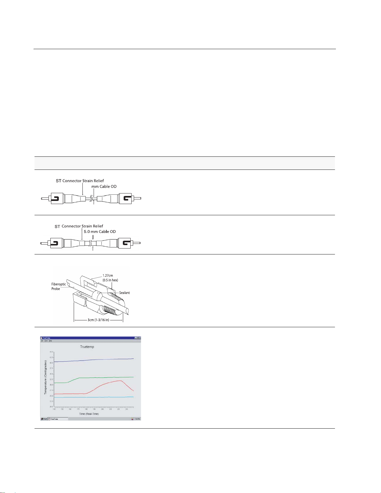
Other accessories include vacuum fittings and PC data acquisition
and graphing software. See Table 2-1 below for a description of
standard accessories.
Table 2 -1 Standard Accessories for Use with FOT Lab Kit
3.0
SST Extension
Application: General purpose fiber optic
extension cable
Connector: ST, both ends
HST Extension
Application: Heavy duty fiber optic
extension cable
Connector: ST, both ends
Compression Gland Feedthrough
Temp Range: -20 to 230
Maximum Vacuum Pressure: 5e10-6 Torr
Maximum Pressure 3,000 psi
Compatible with STM, STF, and STR probes
TrueTemp PC Data Acquisition and
Graphing Software
o
C
00-13743-XX
00-13744-XX
90-1462
00-12790-01
2-4 FOT Lab Kit User’s Manual
Artisan Technology Group - Quality Instrumentation ... Guaranteed | (888) 88-SOURCE | www.artisantg.com
Page 22

System Components
FOT Lab Kit User’s Manual 2-5
Artisan Technology Group - Quality Instrumentation ... Guaranteed | (888) 88-SOURCE | www.artisantg.com
Page 23

System Components
2-6 FOT Lab Kit User’s Manual
Artisan Technology Group - Quality Instrumentation ... Guaranteed | (888) 88-SOURCE | www.artisantg.com
Page 24

3 System Operation
Getting Started
The FOT Lab Kit is a fiber optic temperature measurement system.
All standard probes and fiber optic accessories for use with the FOT
Lab Kit have ST-style fiber optic connectors.
This “Getting Started” section will enable you to start basic
measurements, using default setups, with your FOT Lab Kit. For
more details on how to tailor the instrument to your specific needs,
please refer to the user interface details described in Chapter 4,
“User Interface Commands’’ and Chapter 5, “Temperature Data
Reporting’’.
Host Control To access the full features and interface of the FOT Lab Kit, you will
need a PC or host device to communicate via RS-232. If you are
using LUXTRON’s TrueTemp Software, we recommend you install
this software first, before connecting the instrument.
FOT Lab Kit User’s Manual 3-1
Artisan Technology Group - Quality Instrumentation ... Guaranteed | (888) 88-SOURCE | www.artisantg.com
Page 25
System Operation
Connecting and
Installing the
System
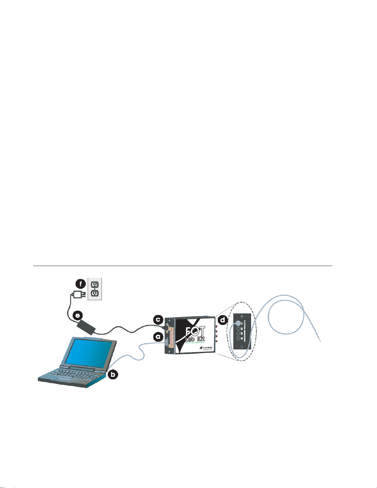
The FOT Lab Kit includes various cables and accessories for
connection. Follow the steps below and refer to Figure 3-1 to setup
the system for operation:
a. Connect the 9-pin male D-sub connector to the RS-232 port
on the instrument.
b. Connect the RS-232 female connector to your computer’s
serial COM port.
c. Connect the power supply’s DIN connector to instrument’s
power inlet.
d. Remove the black dust cap(s) from the instrument’s ST
optical connection(s) and remove the clear protective cap
®
from your Fluoroptic
probe(s). Connect the probe(s) to the
instrument by aligning the polarized connector on the probe
to the optical port and gently push in. Turn clockwise to lock
the connection.
e. Plug power cord into the power supply
f. Plug power supply to a grounded power outlet.
Figure 3-1 Connecting the FOT Lab Kit Components
Fluoroptic Probe
3-2 FOT Lab Kit User’s Manual
Artisan Technology Group - Quality Instrumentation ... Guaranteed | (888) 88-SOURCE | www.artisantg.com
Page 26
System Operation
Making
Temperature
Measurement
Probe Table
Settings
With default factory settings, the FOT instrument will automatically
start making temperature measurements approximately one minute
after power up. To start or stop measurements, use “Action
Commands (One-Letter) in Chapter 4, “User Interface Commands’’.
To adjust measurement rates, analog output values, and other
settings, refer to the “Parameter Commands (Two-Letter)’’, also in
Chapter 4
NOTE Keep the protective black vinyl caps on the unused instrument
probe ports. This prevents ambient light from entering the system, which
could adversely affect the accuracy of temperature measurements from
the remaining active probe(s).
The FOT Lab Kit is designed to work with many different probe
types. There are four standard industrial probes (shown earlier in
Table 2-1 on page 2-4) and some specific industry probes, for
example, medical and power transformer probes. To guarantee
system operation within specifications, the FOT Lab Kit must be
configured to operate with your specific probe type. This is done by
selecting the correct lookup table. See Table 3-1 below to lookup
the correct calibration table for your probe type.
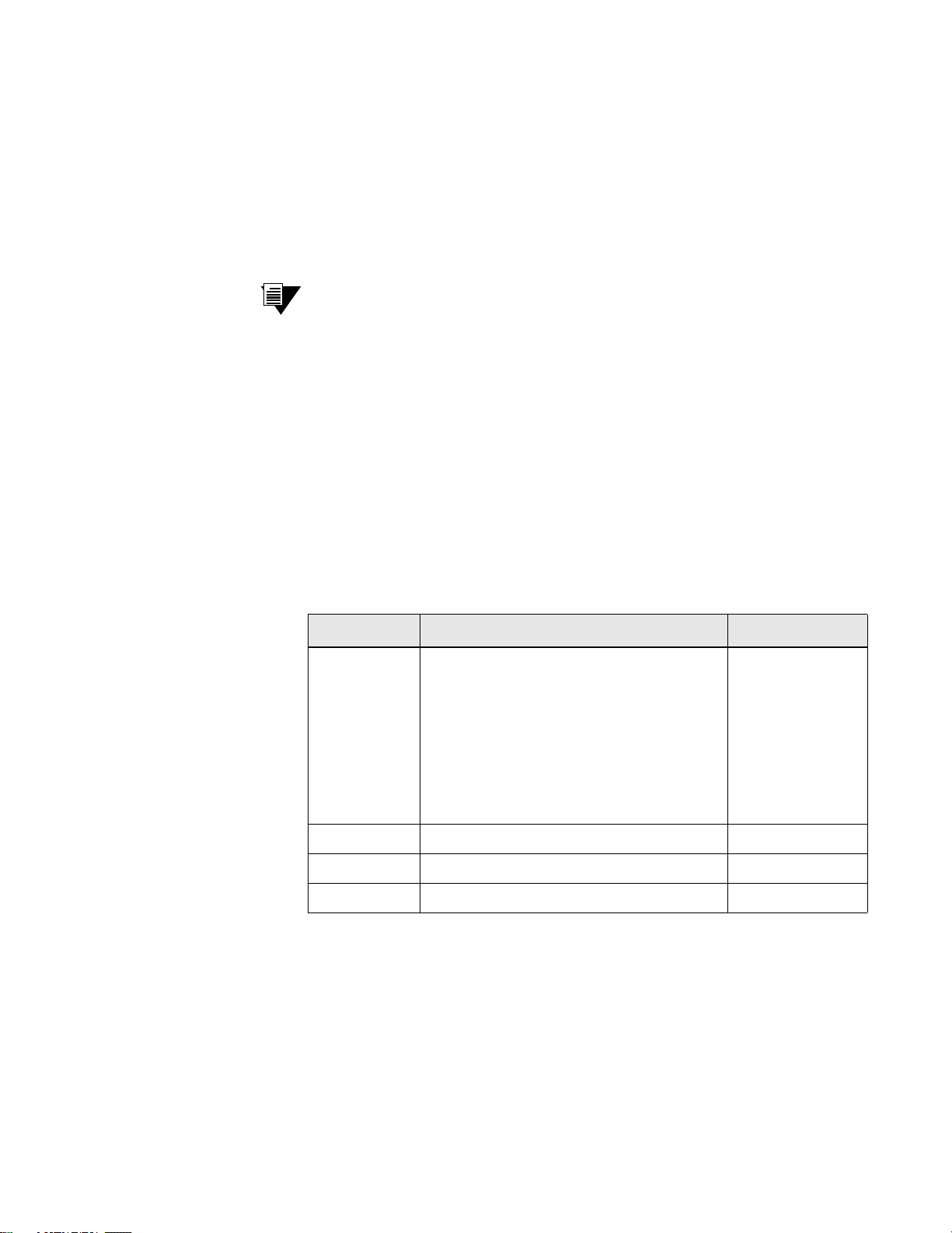
Table 3 -1 List of Correct Lookup Tables for Various Probe Types
Probe Type Description Look Up Table
STF Fast Response Immersion Probe T1
STR Non-contact, Remote Sensing Kit T1
WTS Power Transformer Winding Hot Spot Probe T1
STS Surface Contact Probe T2
STB Medical, 0.5mm Diameter Probe T2
MRC Medical, Core Temperature T2
MRR Medical, Skin and Core Temperature T2
MRS Medical, Skin Temperature T2
STM General Purpose Immersion Probe T3
The FOT Lab Kit's default lookup table is T1. A simple command is
used to change the lookup table. For example, to change the
instrument to operate with table T2, the user sends the following
command: <ESC> T2. Further details of this command are
described in Chapter 4, Page 4-23.
FOT Lab Kit User’s Manual 3-3
Artisan Technology Group - Quality Instrumentation ... Guaranteed | (888) 88-SOURCE | www.artisantg.com
Page 27

System Operation
Analog Outputs The FOT Lab Kit includes a 0-10V analog output for each of the four
measurement channels. There is a positive (+) and Negative (−)
screw terminal contact for each channel. Connections should be
made with shielded 22 AWG wire and a circuit impedance of
>1kOhm.
The FOT Lab Kit can be used with LabVIEW sofware after loading
drivers available on www.luxtron.com.
The analog outputs scaling and offset are programmable. These
settings are adjusted using the AS and AO parameter commands.
For a description and examples of how to use these commands
please see the detailed command definitions on pages 4-7 and 4-8.
User Interface The FOT Lab Kit communicates through a standard RS-232 serial
interface. The connection is a 2-wire interface: Transmit, Receive
and Ground which can be connected to a standard PC equipped
with a 65550 or equivalent UART device. The PC host software may
be a standard terminal emulation application such as
ΤΜ
HyperTerminal
or a custom device-control program
communicating through the RS-232 interface.
The user interface is described in detail in Chapter 4 and Chapter 5
of this manual.
NOTE The serial interface is the main conduit through which the FOT
Lab Kit communicates with the user. The instrument communicates at
9,600 bits-per-second (sometimes erroneously referred to as 9,600
Baud). The bit protocol is 8 data bits, one stop bit and no parity (8-N-
1). The instrument does not use a handshaking protocol.
Calibration Basic temperature calibration is performed at the factory, however
to achieve the highest level of accuracy, it will be necessary to
perform a simple calibration to adjust for the type and positioning
of the temperature probe used. Please refer to Appendix A,
“Calibration Procedure’’, for details on performing this calibration.
3-4 FOT Lab Kit User’s Manual
Artisan Technology Group - Quality Instrumentation ... Guaranteed | (888) 88-SOURCE | www.artisantg.com
Page 28

System Operation
Temperature
Measurement
Range
The range of temperatures that may be measured by the FOT Lab Kit
is limited by the type of probe used. Under no circumstances
should the maximum temperature rating of a probe be exceeded.
Check documentation of your probe or with a LUXTRON
Applications Engineer to determine the specified temperature limits
of your Fluoroptic® probe.
WAR N IN G Exceeding the maximum temperature rating of the probe may
destroy the probe!
Probes LUXTRON’s Fluoroptic® technology uses fiber optic probes
incorporating patented phosphor compounds encapsulated at the
sensing end of the probe. These probes are immune to EMI and
radio-frequency noise, are much more robust that thermocouples
and are ideally suited for hostile environments.
Temperature data are collected by exciting the probe's phosphor
with a burst of light sent through the fiber optic cable. The decaying
light signal returns through the fiber to the instrument where it is
processed by converting the analog signal into a digital value which
is then converted into a calibrated and corrected temperature. The
measured temperature is reported through the RS-232 interface and
the analog outputs.
Operational Note Whenever a probe is disconnected from the device or from a fiber
optic extension cable always install the provided vinyl cap over the
FOT Lab Kit instrument’s optical port. This prevents random
ambient light from entering the system which would adversely affect
the accuracy of the temperature measurements from the remaining
probes.
If you experience unexpected resets of the device during initial
installation and setup, it is likely that the power supply is
improperly grounded. A code is provided in the startup message
indicating the cause of the most recent reset. This code is found at
the end of the first line of the startup message and may be requested
by your Customer Service representative while assisting you with
your installation. The code may be any one of the following:
(POR) Power On Reset (WDR) Watchd og Timer (BOR) Brown Out Reset
(CXR) Ctrl+X Reset (WKR) Wakeup Res et (CLR) MCLR Reset
Example: “Luxtron Corp. Copyright 2002” (POR)
FOT Lab Kit User’s Manual 3-5
Artisan Technology Group - Quality Instrumentation ... Guaranteed | (888) 88-SOURCE | www.artisantg.com
Page 29

System Operation
3-6 FOT Lab Kit User’s Manual
Artisan Technology Group - Quality Instrumentation ... Guaranteed | (888) 88-SOURCE | www.artisantg.com
Page 30

4 User Interface Commands
The primary user interface with the FOT Lab Kit is through a
standard RS-232 serial interface. The host may be a standard
terminal emulation application software such as HyperTerminal™ or
a custom device-control program communicating through the RS232 interface. LUXTRON also offers a Windows-based graphing and
data-acquisition program for PCs called TrueTemp™.
The instrument communicates at 9,600 bits-per-second. The bit
protocol is 8 data bits, one stop bit and no parity (8-N-1). The
instrument does not use a handshaking protocol. The details of the
communication protocol are defined in this chapter and Chapter 5,
“Temperature Data Reporting” .
User interface commands fall into two general categories:
1. Parameter Commands: Two-letter command codes with
required or optional arguments.
2. Action Commands: One-letter character command codes
consisting of the Control key plus one letter key.
For a summary of the Parameter Commands, see Table 4-1 on
page 4-5. For a summary of the Action Commands, see Table 4-2 on
page 4-5.
FOT Lab Kit User’s Manual 4-1
Artisan Technology Group - Quality Instrumentation ... Guaranteed | (888) 88-SOURCE | www.artisantg.com
Page 31

User Interface Commands
Parameter Commands (Two-Letter)
The Parameter Commands are used to adjust user-selectable
parameters and to query the instrument to report a current
parameter setting.
The Parameter Command code consist of the Escape character
(1Bh) followed by two ASCII characters defining the command with
optional arguments for retrieving information or setting system
parameters. Commands are not case sensitive.
White space (spaces/tabs) is allowed but is ignored except where it
is necessary for separation of arguments.
All commands must be terminated by a carriage-return character CR
(0Dh) optionally followed by a line feed character LF (0Ah).
These parameter commands are used in either of two ways:
information requests or parameter modification.
Information
Requests
This command format consists of the Escape character followed by a
two-letter command followed by a question mark and carriage
return/line feed.
Example Query: <Esc>AA ? <CRLF>
Information Request
Character Hexidecimal
Escape 1Bh
A 41h
A 41h
Space (optional) 20h
?3Fh
Carriage Return 0Dh
Line feed 0Ah
Informational output data packets consist of echoing the command
code in upper case characters followed by an equal sign ( = )
followed by the requested information. The Escape character is not
echoed.
White space is consistently applied with exactly one (1) space
character between each pair of arguments.
4-2 FOT Lab Kit User’s Manual
Artisan Technology Group - Quality Instrumentation ... Guaranteed | (888) 88-SOURCE | www.artisantg.com
Page 32

User Interface Commands
Informational output data is always terminated by a carriage-return/
line feed pair (CRLF).
Example Response: AA = INFO
Information Request
Character Hexidecimal
A 41h
A 41h
Space 20h
=3Dh
Space 20h
I--
N--
F--
O--
Carriage Return 0Dh
Line Feed 0Ah
If the command is unrecognized or the command syntax is incorrect
the system responds with the request as typed with the addition of a
question mark '?' followed by a CRLF pair.
The system responds to the information request as described,
although certain exceptions exist; e.g. multi-line responses. Refer to
the descriptions of the individual commands for additional details.
FOT Lab Kit User’s Manual 4-3
Artisan Technology Group - Quality Instrumentation ... Guaranteed | (888) 88-SOURCE | www.artisantg.com
Page 33

User Interface Commands
Parameter
Modification
This command format consists of the Escape character followed by a
two-letter command followed by an equal sign ('=') and the new
parameter value(s) and ending with a carriage return/line feed.
These commands provide the mechanism for modification of setup
parameters or for initiation of an event or sequence of events.
Example Command: <Esc>AA = E <CRLF>
Information Request
Character Hexidecimal
Escape 1Bh
A 41h
A 41h
Space (optional) 20h
=3Dh
Space (optional) 20h
E 45h
Carriage Return 0Dh
Line feed 0Ah
If the command is successfully received, parsed and executed, the
new parameter will immediately take effect. There will be no serialdata response from the device.
If the command is unrecognized or the command syntax or
parameter value is incorrect the system responds with the request as
typed with the addition of a question mark '?' followed by a CRLF
pair.
4-4 FOT Lab Kit User’s Manual
Artisan Technology Group - Quality Instrumentation ... Guaranteed | (888) 88-SOURCE | www.artisantg.com
Page 34

User Interface Commands
Table 4 -1 Summary Listing of Parameter Commands
Command Code Command Description
AE Analog Output Enable Enable/Disable Analog Outputs
AO Analog Output Set Analog-Output Temperature Offset Factor
AS Analog Scaling Factor Set Analog-Output Temperature Scaling Factor
CC Calibration Correction Enable/Disable Application of Calibration Factors
CT Calibration Set Calibration Temperature for Auto-Calibration Function
DF Data Format Set Serial Data Output Format
DS Data String Capture User Data Sequence
HL High Temperature Limit Set High Temperature Limit (obsolete, no longer supported)
ID Information Display Report Device ID and Current Parameter Settings
LL Low Temperature Limit Set Low Temperature Limit (obsolete, no longer supported)
MU Measurement Update Set Interval Between Temperature Measurement Reports
PS Probe Select Specify Active-Input List
SL Signal Level Report LED Light Source Intensity Level
SM Sample Measurement Set Number of Samples to be Retained Per Measurement
SN Serial Number Report Device's Serial Number
ST STart up Mode Select Startup Mode
SV Save Parameters Save Current User Parameters and Calibration Factors
TU Table Selection Reports the Currently Selected Look-up Table
UN Output Units Specify Output Units of Measure
Table 4 -2
Command Code Command Description
CTRL + A
CTRL + D
CTRL + E
CTRL + F
CTRL + I
CTRL + K
CTRL + Q
CTRL + S
CTRL + T
CTRL + X
Abort (01h) Abort calibration sequence in progress
Disable (04h) Disable remote control of temperature reporting
Enable (05h) Enable remote control of temperature reporting
Flush (06h) Flush the measurement buffer
Initiate (09h) Begin data sampling
Calibrate (0Bh) Begin auto-calibration sequence
Report (11h) Report the most recent measurement / enable serial output
Stop (13h) Disable serial data output
Standby (14h) Enter standby mode
Reset (18h) Reset the instrument
Summary Listing of Action Commands
FOT Lab Kit User’s Manual 4-5
Artisan Technology Group - Quality Instrumentation ... Guaranteed | (888) 88-SOURCE | www.artisantg.com
Page 35

User Interface Commands
AE Analog Output Activation
Enable all analog output channels which are attached to active
inputs. For each input channel that has been enabled using the PS
command, enable the corresponding analog output channel.
Information Request:
Syntax: <Esc>AE ? <CRLF>
Response: AE = ENABLED | DISABLED
Command Parameters:
Syntax: <Esc>AE = status <CRLF>
Range:
ENABLE Enable the analog outputs for all active inputs
DISABLE Disable all analog outputs
Examples: <Esc>AE = ENABLE <CRLF>
<Esc>AE = E <CRLF>
<Esc>AE = Disable <CRLF>
<Esc>AE = D <CRLF>
4-6 FOT Lab Kit User’s Manual
Artisan Technology Group - Quality Instrumentation ... Guaranteed | (888) 88-SOURCE | www.artisantg.com
Page 36

AO Analog Output Offset
Set the temperature offset (minimum reported temperature) for
analog output voltage. Along with the Analog Scaling Factor (AS
command) the AO command sets the parameters for the analog
output voltage range.
The native range for analog output channels is 0.00 to 10.00V. The
analog temperature offset is expressed in degrees (using the
specified system units). By adjusting the temperature offset it is
possible to set the floor of the analog output range i.e. the
temperature corresponding to 0.00V output.
V
= (AS/1000) * (T
out
Where:
AO = AnalogOffset = Minimum analog output voltage
corresponding to minimum reported temperature
AS = Analog Scaling Factor, mV/deg
(see AS command, page 4-8)
V
out
T
measured
= Analog output voltage
= Temperature measured at input
User Interface Commands
measured
- AO)
The default temperature offset value is equivalent to the minimum
temperature supported by the device.
See examples in description of AS command, page 4-8.
Information Request:
Syntax: <Esc>AO ? <CRLF>
Response: AO = offset in degrees
o
Example: AO = -30
C
Command Parameters:
Syntax: <Esc>AO = offset <CRLF>
Range:
This value is not range checked. Use care in selection of parameter
value.
FOT Lab Kit User’s Manual 4-7
Artisan Technology Group - Quality Instrumentation ... Guaranteed | (888) 88-SOURCE | www.artisantg.com
Page 37

User Interface Commands
AS Analog Output Scaling
Set the scaling factor for analog output voltage. Along with the
Analog Offset (AO command) the AS command sets the parameters
for the analog output voltage range.
The native range for analog output channels is 0.00 to 10.00V. The
scaling factor is expressed in millivolts per degree. By adjusting the
scaling factor it is possible to adjust the working range of the analog
outputs as they apply to the input temperature range.
V
= (AS/1000) * (T
out
Where:
AO = AnalogOffset = Minimum analog output voltage
corresponding to min. reported temperature
(see AO command, page 4-7)
AS = Analog Scaling Factor (in millivolt per degree,
mV/deg)
V
out
T
measured
= Analog output voltage
= Temperature measured at input
measured
- AO)
Minimum Input
Temperature
o
-30
C330
Maximum Input
Temperature
o
C 27.7778mV / oC-30oC 0V 10.0V 10.0V
The default scaling factor value is based upon the temperature
range supported by the device.
Example using standard-configuration defaults:
VOutput Scaling
Factor
Temperature
Offset
Minimum
Output Voltage
Maximum
Output Voltage
Output
Voltage Range
Information Request:
Syntax: <Esc>AS ? <CRLF>
Response: AS = scaling factor in mV / degree
Example: AS = 27.7778
Parameter Modification:
Syntax: <Esc>AS = factor<CRLF>
Range:
This value is not range checked. Use care in selection of parameter
value.
4-8 FOT Lab Kit User’s Manual
Artisan Technology Group - Quality Instrumentation ... Guaranteed | (888) 88-SOURCE | www.artisantg.com
Page 38

User Interface Commands
Example using a temperature range of 0.00oC to 200oC:
Minimum Input
Temperature
o
C 200 oC 50 mV / oC0oC 0V 10.0V 10.0V
0
Maximum Input
Temperature
VOutput
Scaling Factor
0V = (50mV /
Temperature
Offset
o
C * 1V/1000mV) * (0oC - 0oC)
Minimum
Output Voltage
Maximum
Output Voltage
5V = (50mV / oC * 1V/1000mV) * (100oC - 0oC)
10V = (50mV / oC * 1V/1000mV) * (200oC - 0oC)
Output Voltage
Range
FOT Lab Kit User’s Manual 4-9
Artisan Technology Group - Quality Instrumentation ... Guaranteed | (888) 88-SOURCE | www.artisantg.com
Page 39

User Interface Commands
CC Calibration-Correction
The CC command is used to Enable or Disable application of the
Calibration-Correction Factors. Each installed temperature input
channel has associated calibration factors which are applied to the
measured temperature before it is reported.
These factors are set to typical values at the factory but must be
fine-tuned as needed to compensate for differences in probe type,
probe length and signal attenuation factors such as positioning and
optical fiber bend-radius inherent in your particular installation.
Please refer to Appendix A, “Calibration Procedure” for additional
details.
Information Request:
Command Syntax: <Esc>CC? <CRLF>
Response Syntax: CC = info
ENABLE Application of the Calibration-Correction Factors is enabled.
DISABLE Application of the Calibration-Correction Factors is disabled.
Parameter Modification:
Syntax: <Esc>CC=status <CRLF>
Range:
ENABLE (default) Enables application of Calibration-Correction Factors
DISABLE Disables application of Calibration-Correction Factors
Example: <Esc>CC = ENABLE <CRLF>
<Esc>CC = E <CRLF>
4-10 FOT Lab Kit User’s Manual
Artisan Technology Group - Quality Instrumentation ... Guaranteed | (888) 88-SOURCE | www.artisantg.com
Page 40

CT Calibration Temperature
The CT command is used to set the calibration reference
temperature used during the automatic calibration-correction
procedure.
Please refer to Appendix A, “Calibration Procedure” for additional
details.
Information Request:
Syntax: <Esc>CT ? <CRLF>
Response: CT = caltemp
Example: CT = 37.00 C
Parameter Modification:
Syntax: CT = caltemp <CRLF>
Range: caltemp New calibration reference temperature
The new reference temperature is specified in degrees and
hundredths of a degree within the working range of the device.
Temperature units are assumed to be the units previously set
using the UN command.
User Interface Commands
Value input is in "nn.nn" format. Do not include the units. If
the reference temperature entered is of an ambiguous format
e.g. "40" or "40.1" the system will correctly interpret the input
as "40.00" and "40.10" respectively. It is recommended,
however that values be entered in the standard format.
Example: <Esc>CT = 95.50 <CRLF>
FOT Lab Kit User’s Manual 4-11
Artisan Technology Group - Quality Instrumentation ... Guaranteed | (888) 88-SOURCE | www.artisantg.com
Page 41

User Interface Commands
DF Data Format
The DF command sets the serial-interface temperature output
format, either full or abbreviated.
The format selected depends upon the use to which the captured
data will be put. For visual clarity the abbreviated format is
recommended for most circumstances.
Information Request:
Syntax: <ESC>DF ? <CRLF>
Response: DF = format
Parameter Modification:
Syntax: DR = format <CRLF>
Range: FULL
FULL
Output is formatted for all channels without regard to the
number of active channels.
Returns the current data reporting format.
Examples:
All four input channels are active.
" 1: 20.42 C 2: 22.75 C 3: 21.25 C 4: 19.97 C"
Input channels 1 and 2 are active.
" 1: 20.42 C 2: 22.75 C 3: 4: "
Input channels 1 and 3 are active.
" 1: 20.42 C 2: 3: 22.75 C 4: "
ABBR
Output is compacted to display data for only active input
channels.
All four input channels are active.
" 1: 20.42 C 2: 22.75 C 3: 21.25 C 4: 19.97 C"
Input channels 1 and 2 are active.
" 1: 20.42 C 2: 22.75 C"
Input channels 1 and 3 are active.
" 1: 20.42 C 3: 21.25 C"
4-12 FOT Lab Kit User’s Manual
Artisan Technology Group - Quality Instrumentation ... Guaranteed | (888) 88-SOURCE | www.artisantg.com
Page 42

DS Display String
The DS command may be used by the OEM customer to enter a line
of text to be displayed on startup. This text will also be displayed as
part of the parameter dump (see example in description of ID
command, page 4-14).
Information Request:
Syntax: <Esc>DS ? <CRLF>
Response: DS = OEM display string
Example: DS = XYZ Corp. Model SuperPro 5000
Parameter Modification:
Syntax: <Esc>DS = OEM display string <CRLF>
Range: Display string may be from 1 to 31 characters.
NOTE Characters must be standard ASCII printing characters. If the first
character after the '=' sign is a Space (20h) it will be discarded.
User Interface Commands
.
To prevent display of this string enter an empty string i.e. press
Enter key immediately after the Equal sign ('='): <Esc>DS
=<CR>
Example Sign-On Message:
LUXTRON CORP.
Copyright 2002
M600 Fluoroptic Thermometer, Software Version 1.00
Serial # 12345
XYZ Corp. Model SuperPro 5000
FOT Lab Kit User’s Manual 4-13
Artisan Technology Group - Quality Instrumentation ... Guaranteed | (888) 88-SOURCE | www.artisantg.com
Page 43

User Interface Commands
ID Identification Query
The ID command is used to report the device's identification string,
firmware version, device serial number and current operating
parameters. In essence this command combines the information
requests of most other system commands into an inclusive report.
The DS and SN command data are incorporated into the header
information. The SL command values, being dynamic are not
included in the report.
Information Request:
Syntax: <Esc>ID ? <CRLF>
Response: ID = info
Example:
LUXTRON CORP. Copyright 2002
M600 Fluoroptic Thermometer, Software Version 1.00
Serial # 12345
XYZ Corp. Model SuperPro 5000
PS = 1,2,3,4
SM = 8
MU = 1 S
UN = CELSIUS
DF = ABBR
AE = ENABLE
AS = 27.7778
AO = -30.00 C
CC = ENABLE|
CT = 75.00 C
MS = DISABLE
ST = ENABLE
Please refer to the descriptions of the individual commands related
to the reported parameters for details on interpreting the
information.
Parameter Modification:
n/a
4-14 FOT Lab Kit User’s Manual
Artisan Technology Group - Quality Instrumentation ... Guaranteed | (888) 88-SOURCE | www.artisantg.com
Page 44

User Interface Commands
MU Report/Set Measurement Reporting Interval
The MU command specifies the interval between measurement
reports. Another way of looking at it is that 1 / MU = reporting
frequency.
Information Request:
Syntax: <Esc>MU ? <CRLF>
Response: MU = interval
Example: MU = 4.5 S
Parameter Modification:
Syntax: <Esc>MU = interval <CRLF>
Range: C or 'Continuous
Continuous mode reporting sets the reporting
interval to the minimum practical value i.e. the
sample interval times the number of active
channels. Since the sample rate is 4 Hz the
sample interval is then 250 milliseconds and
the reporting interval will be 250mS * channels.
Examples:
If 4 channels are active MU=C would yield 250mS * 4 = 1.0 S.
If 2 channels are active MU=C would yield 250mS * 2 = 0.5 S.
0.25 - 600 S Interval may be specified in seconds
1 - 10 M Interval may also be specified in minutes
The minimum interval corresponds to the sample rate of 0.25
Seconds (4Hz).
The maximum interval is limited by the width of the timer (16 bits).
Examples: <ESC> MU = C <CRLF>
<ESC> MU = 25 <CRLF>
<ESC> MU = IM <CRLF>
FOT Lab Kit User’s Manual 4-15
Artisan Technology Group - Quality Instrumentation ... Guaranteed | (888) 88-SOURCE | www.artisantg.com
Page 45

User Interface Commands
PS Active Input Channels
The PS (Probe Select) command specifies which input channels are
to be activated.
It is recommended that unused inputs be disabled to provide the
optimum number of samples per report for the active channels.
The number of active channels has a direct effect on the
interpretation of the MU command parameter value 'C' i.e.
continuous reporting.
Information Request:
Syntax: <Esc>PS ? <CRLF>
Response: PS = active channel list
Example: PS = 1,2,3,4
Parameter Modification:
Syntax: <Esc>PS = channel list <CRLF>
Range: Any combination of installed channels may
be specified, in any order with the channel
numbers separated by commas. Additional
spaces may be used but are ignored if
present.
Examples: PS = 1, 2, 3, 4
PS = 2, 4
PS = 3, 1, 2
4-16 FOT Lab Kit User’s Manual
Artisan Technology Group - Quality Instrumentation ... Guaranteed | (888) 88-SOURCE | www.artisantg.com
Page 46

SL Signal Level
The SL command reports the relative strength of the signal arriving
at the photodetector. The signal is the intensity of light returned
from the probe tip and is reported as a percentage of maximum.
This information is used primarily during probe testing and helps to
determine whether the probe is functioning efficiently.
Information Request:
Syntax: <Esc>SL ? <CRLF>
Response: SL = signal
Example:
1: 1.81 % 2: 2.66 % 3: 5.10 % 4: 3.24 %
User Interface Commands
The signal data are returned in the same general
format as a standard temperature report.
Parameter Modification:
n/a
FOT Lab Kit User’s Manual 4-17
Artisan Technology Group - Quality Instrumentation ... Guaranteed | (888) 88-SOURCE | www.artisantg.com
Page 47

User Interface Commands
SM Samples per Measurement
The SM command is used to specify the number of ADC samples
that will be averaged to create each measurement reported. Fewer
samples mean faster response, more samples mean greater stability.
The FOT Lab Kit’s internal timing is based upon a fixed 4Hz
sampling rate. The number of samples per second per channel is
4Hz divided by the number of active channels.
The Samples-per-Measurement command specifies the number of
samples retained per channel which are then averaged to generate
the temperature report. To put it another way, the specified number
of samples will be averaged and used to create the temperature
value to be reported.
NOTE Please note also that the measurement update rate (MU
command) has an impact upon averaging in that it determines the
degree to which averaging occurs across measurements.
Examples: In the first example only one input channel is active so
all samples taken are for that channel. Each report (except the first)
will include 8 samples. In the second example four channels are
active so the samples taken are distributed evenly among the active
channels. Each report (except the first) will then include 2 samples
per channel.
4-18 FOT Lab Kit User’s Manual
Artisan Technology Group - Quality Instrumentation ... Guaranteed | (888) 88-SOURCE | www.artisantg.com
Page 48
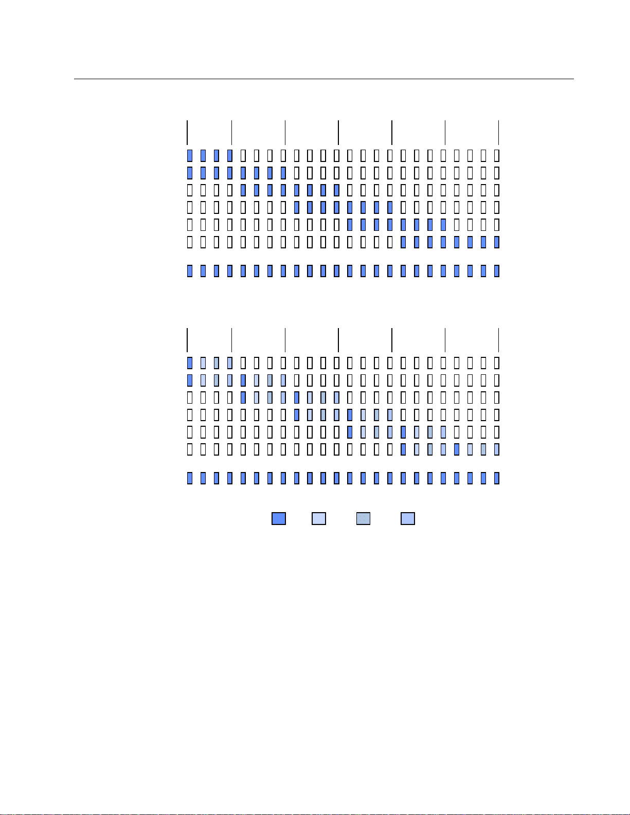
Figure 4-1 Sampling Report
Exam p le: On e inp ut channel is active, MU = 1 Secon d, SM = 8 Sam ples Per Repo rt
User Interface Commands
Seconds
Report 1
Report 2
Report 3
Report 4
Report 5
Report 6
Report 7
Sampling Rate
4 Per Second
Seconds
Report 1
Report 2
Report 3
Report 4
Report 5
Report 6
Report 7
1 2 3 4 5 6
Example: Four inp ut channel are active, M U = 1 Seco nd, SM = 2 Sam p les Per Repo rt
1 2 3 4 5 6
Sampling Rate
4 Per Second
C h a n n e l 1 C h a n ne l 2 C h a nn e l 3 C h a n n e l 4
Information Request:
Syntax: <Esc>SM ? <CRLF>
Response: SM = samples
Example: SM = 6
(Six samples averaged into each reported value)
Parameter Modification:
Syntax: <Esc>SM = samples <CRLF>
Range: 1 through 50
FOT Lab Kit User’s Manual 4-19
Artisan Technology Group - Quality Instrumentation ... Guaranteed | (888) 88-SOURCE | www.artisantg.com
Page 49

User Interface Commands
SN Serial Number Query
The SN command is used to report the unit's internal serial number.
A copy of this number may or may not also be affixed to the unit's
case.
Information Request:
Syntax: <Esc>SN ? <CRLF>
Response: SN = sernum
Example: SN = 123456
In the unlikely event that the serial number saved in NvRam has
been corrupted the message "SN = Undefined" will be returned.
Parameter Modification
n/a
4-20 FOT Lab Kit User’s Manual
Artisan Technology Group - Quality Instrumentation ... Guaranteed | (888) 88-SOURCE | www.artisantg.com
Page 50

ST Startup Mode
The ST command is used to select the "startup mode" indicating to
the device whether to power up into Standard mode or into
Standby mode.
In Standard mode the input circuits are enabled and the device
begins reporting temperatures as soon as data are ready.
In Standby mode the input circuits are idle i.e. samples are not
being taken and no data reports will be generated. In this mode the
user must explicitly enter Standard mode using the CTRL+R
command to enable data sampling and reporting.
NOTE Do not issue the CTRL+R command for at least 30 seconds after
power-up which will allow the device time to complete its startup
sequence.
See also the descriptions of the CTRL+T and CTRL+R commands.
User Interface Commands
Information Request:
Syntax: <ESC>ST ? <CRLF>
Response: ST = mode
Examples:
ST = ENABLE Temperature reporting starts automatically.
ST = DISABLE Reporting must be started manually.
ST = E Same as ST = Enable
Parameter Modification:
Syntax: <ESC>ST = mode
Range: ENABLE Begin reporting temperatures on power up.
DISABLE On startup wait for user to enable
temperature reports.
FOT Lab Kit User’s Manual 4-21
Artisan Technology Group - Quality Instrumentation ... Guaranteed | (888) 88-SOURCE | www.artisantg.com
Page 51

User Interface Commands
SV Save
The SV command is used to copy the currently active user
parameter values and input-channel calibration factors to nonvolatile (NvRam) storage for use in subsequent sessions.
When user parameters are changed or when the instrument is
calibrated the resulting values are active only for the current session
i.e. until the instrument is reset using the CTRL+X command or
until the instrument is powered down. This allows you to
experiment with different parameter combinations without affecting
the stored parameters. If you wish to save the new calibration
factors and user parameters for subsequent sessions you must
explicitly save them using the SV command.
Information Request:
n/a
Parameter Modification:
Syntax: <Esc>SV <CRLF>
Response: none
4-22 FOT Lab Kit User’s Manual
Artisan Technology Group - Quality Instrumentation ... Guaranteed | (888) 88-SOURCE | www.artisantg.com
Page 52

TU Table Selection
The TU query reports the currently selected "tau to temperature"
lookup table. The FOT Lab Kit includes three such tables for use
with different probe types.
Information Request:
Syntax: <ESC> TU ? <CRLF>
Response: Using Table: 1
Parameter Modification:
Syntax: <ESC> T1 <CRLF>
Response: Set T1
Syntax: <ESC> T2 <CRLF>
Response: Set T2
Syntax: <ESC> T3 <CRLF>
Response: Set T3
User Interface Commands
FOT Lab Kit User’s Manual 4-23
Artisan Technology Group - Quality Instrumentation ... Guaranteed | (888) 88-SOURCE | www.artisantg.com
Page 53

User Interface Commands
UN Unit of Measure
The UN command is used to report or select the serial-interface data
output units. Three units are currently supported: Kelvin, Celsius
and Fahrenheit. The analog outputs are mapped directly from the
serial output units.
NOTE For legacy reasons it is important to select the output units first
before adjusting any other system parameters. Units should not be
changed after other parameters are set or after calibration has been
performed. If you change units the device will need to be recalibrated.
Information Request:
Syntax: <Esc>UN ? <CRLF>
Response: UN = units
Reports the current units/data type being transmitted through
the user interface.
CELSIUS Temperature in degrees Celsius
KELVIN Temperature in degrees Kelvin
FAHRENHEIT Temperature in degrees Fahrenheit
Parameter Modification:
Syntax: <Esc>UN = units
Range: CELSIUS
KELVIN
FAHRENHEIT
Examples:<Esc>UN = KELVIN
<Esc>UN = K
4-24 FOT Lab Kit User’s Manual
Artisan Technology Group - Quality Instrumentation ... Guaranteed | (888) 88-SOURCE | www.artisantg.com
Page 54

Action Commands (One-Letter)
Several commands which perform a simple function without the
need of parameter data from the user are implemented as single-
character commands. These commands consist of holding down
the Control key (CTRL) and pressing one additional key. See the
Summary of Commands below.
These commands are used to enable or disable an operation,
initiate or terminate an event etc. If the command is successfully
received and executed the character is echoed back.
NOTE Many of these characters will not print through a terminal
emulation application or may print as semi-graphic or garbage
characters so it is sometimes difficult to determine whether the device
has responded properly simply by looking. This, of course is not a
problem when the device is under the control of a custom control
program since in that case the character is not displayed, but is simply
recognized as just another number.
User Interface Commands
Modes of
Operation
The FOT Lab Kit user interface includes eleven (11) one-letter
Action Commands that instruct the instrument to perform a
function or switch mode. Conceptually, there are four "modes"
defined for the FOT Lab Kit device. A summary listing of these
commands in Table 4-2 on page 4-5.
The FOT Lab Kit has four different operation modes. The Active
Commands are used to switch from one mode to another, or to
initiate specific events while the FOT Lab Kit is in a particular
operational mode. The four modes are Standard, Remote control,
Stand by, and Calibration.
Standard Mode
In Standard mode temperatures are reported periodically
based upon the interval set using the MU command.
Remote Control Mode
In Remote Control mode temperatures are reported only when
the PC host requests them.
FOT Lab Kit User’s Manual 4-25
Artisan Technology Group - Quality Instrumentation ... Guaranteed | (888) 88-SOURCE | www.artisantg.com
Page 55

User Interface Commands
Standby Mode
In Standby mode sampling and temperature reporting are
disabled and the device simply waits for additional commands
from the PC host.
Calibration Mode
In Calibration mode sampling and temperature calculation are
still active but the temperatures, rather than being reported are
used to calculate new calibration factors.
Of the one-letter codes described below some are valid only in
certain operational modes or have different functionality in different
modes. For this reason the sequence in which these commands are
entered is significant. Please read the command descriptions
carefully to obtain optimal results and avoid confusion.
Example of a typical Remote Control mode session:
■ Place device into Standby mode using CTRL+T.
■ Place device into Remote Control mode using CTRL+E.
■ Send the Run command CTRL+R.
■ Send the Initiate Measurement command CTRL+I. Wait for
CTRL+I to be echoed.
■ Send the Report Measurement command CTRL+Q. The
report will be transmitted.
■ Repeat steps 4 and 5 as desired.
■ Return to from Remote Control mode to Standard mode using
CTRL+D.
■ Re-enable periodic temperature reporting using CTRL+R.
4-26 FOT Lab Kit User’s Manual
Artisan Technology Group - Quality Instrumentation ... Guaranteed | (888) 88-SOURCE | www.artisantg.com
Page 56

CTRL+A Abort Calibration Sequence in Progress
When a calibration sequence has been initiated using the CTRL+K
command the device will begin taking data from which to calculate
the new calibration factors. The length of a calibration period is
typically anywhere from 5 to 40 seconds. If the input data are
invalid or cannot be properly integrated into the calibration
algorithm the instrument will automatically abort the sequence after
one minute. You may also abort the calibration sequence at any
time using the CTRL+A command. If a calibration sequence is
successfully aborted the CTRL+A character will be echoed back to
the host, else there is no response.
NOTE If the calibration sequence is aborted the previous calibration
factors are not restored and the system will be left in an indeterminate
state. You must then perform a successful calibration before using the
device to capture calibrated temperature data. You may still operate
the device in uncalibrated mode (CC = DISABLE command)
User Interface Commands
CTRL+D Exit Remote Control Mode
This command is valid ONLY when the device is in Remote Control
mode (CTRL+E command).
Disable the Remote Control mode of temperature reporting and
return to Standard Mode. If command is successfully executed the
CTRL+D character will be echoed back to the host, else a question
mark ('?') will be returned.
CTRL+E Enable Remote Control Mode
This command is valid ONLY when the device is in Standby mode
(CTRL+T command).
Exit Standby mode and enable Remote Control mode temperature
reporting. In Remote Control mode temperature reports are
created and transmitted only when the PC host requests them. If
command is successfully executed the CTRL+E character will be
echoed back to the host, else a question mark ('?') will be returned.
FOT Lab Kit User’s Manual 4-27
Artisan Technology Group - Quality Instrumentation ... Guaranteed | (888) 88-SOURCE | www.artisantg.com
Page 57

User Interface Commands
CTRL+F Flush the Measurement Buffer
Discard any data currently stored in the measurement buffer. Use
this command when you want to discard old data to prevent it from
affecting new data. For example you may have just installed a new
probe and want to discard any garbage data still in the input buffer.
Old data will, of course cycle out on its own but may take several
seconds depending upon the combination of system parameters
you have selected. This command simply speeds up that process.
The CTRL+F character will be echoed back to the host.
CTRL+I Create a Data Report
This command is valid ONLY when the device is in Remote Control
mode (CTRL+E command).
The CTRL+I command initiates data sampling and the creation of
one temperature report. When the report is ready the device will
echo the CTRL+I character. You may then request the report be
transmitted using the CTRL+Q command.
CTRL+K Initiate Auto-Calibration Sequence
This command is valid ONLY when the device is in Standard mode.
The CTRL+K command invokes the auto-calibration sequence for
all active inputs. When the sequence is complete the device will
report the status of the operation as shown with the status indicator
immediately following the colon (':') and the calibration
temperature. Please see Appendix A, “Calibration Procedure” for
further details.
1:C 348.15 K 2:C 348.15 K 3:C 348.15 K 4:C 348.15 K
4-28 FOT Lab Kit User’s Manual
Artisan Technology Group - Quality Instrumentation ... Guaranteed | (888) 88-SOURCE | www.artisantg.com
Page 58

CTRL+Q Report the Most Recent Measurement
When in Remote Control mode periodic reporting of temperature
through the serial interface is disabled even though sampling and
creation of temperature reports can be invoked as background tasks
(CTRL+I command). The CTRL+Q command instructs the device
to report the most recent measurement created for each active
input. The format of the report is exactly the same as when in
automatic-reporting mode except that it is preceded by the echo of
the CTRL+Q character. Under normal circumstances the user
would alternate between CTRL+I (create report) and CTRL+Q
(transmit report). If you transmit CTRL+Q twice without an
intervening CTRL+I, you will receive a copy of the old report
created by the most recent CTRL+I command.
When used in Standard mode the CTRL+Q command simply
enables RS-232 serial data output previously inhibited by the
CTRL+S command.
User Interface Commands
CTRL+R Exit Standby Mode / Run
This command is valid ONLY when the device is in Standby mode
(CTRL+T command) or Remote Control mode (CTRL+E
command).
When in Standby mode CTRL+R instructs the device to return to
Standard-mode operation.
When in Remote Control mode CTRL+R enables, but does not
initiate data sampling.
If command is successfully executed the CTRL+R character will be
echoed back to the host, else a question mark ('?') will be returned.
CTRL+S Disable Serial Data Output
This command is valid ONLY when the device is in Standard mode.
Use CTRL+S to temporarily disable periodic reporting of
temperature data. A common reason for doing this is to prevent the
data you are looking at from scrolling off the screen. Use CTRL+Q
to restart periodic reporting.
FOT Lab Kit User’s Manual 4-29
Artisan Technology Group - Quality Instrumentation ... Guaranteed | (888) 88-SOURCE | www.artisantg.com
Page 59

User Interface Commands
CTRL+T Enter Standby Mode
This command is valid ONLY when the device is in Standard mode
(CTRL+R command) or Remote Control mode (CTRL+E
command).
The CTRL+T command causes the device to enter Standby mode (if
not already in Standby). Standby mode can be thought of as a lowpower mode in that the lamps are turned off and temperature
reporting disabled. If command is successfully executed the
CTRL+T character will be echoed back to the host, else a question
mark ('?') will be returned.
CTRL+X Reset the Instrument
The CTRL+X command is used to perform a software reset of the
FOT Lab Kit device. This software reset is exactly equivalent to
cycling power to the unit.
All parameters will be loaded from NvRam exactly as they are on
power up.
If the parameters in any section of NvRam have been corrupted,
factory defaults will be loaded for that section and a message will be
displayed informing the user which section(s) have received the
factory default values.
4-30 FOT Lab Kit User’s Manual
Artisan Technology Group - Quality Instrumentation ... Guaranteed | (888) 88-SOURCE | www.artisantg.com
Page 60

5 Temperature Data
Reporting
RS-232 Serial Interface Data Format
General Format
Specification
Temperature data are reported for each active input channel. The
temperature units are selected using the UN command. The format
of the report is selected using the DF command.
The general format is to display the channel number followed by
the temperature measurement for the channel followed by the units
designator: 1: 245.71 K
This general format is followed for each input channel from lowest
to highest, concatenating the data and presenting it on a single
output line.
■ The data for each channel are presented in a fixed-length
format.
■ Each output line is terminated by a carriage return / linefeed
pair.
■ There are two basic formats for serial output: FULL and
ABBRIEVIATED. This format is selected using the DF (Data
Format) command.
FOT Lab Kit User’s Manual 5-1
Artisan Technology Group - Quality Instrumentation ... Guaranteed | (888) 88-SOURCE | www.artisantg.com
Page 61

Temperature Data Reporting
_
The following is an exact breakdown in both ASCII and hexidecimal
of a report where input channels 1 and 2 are active and DF = ABBR.
Space characters are replaced by the underscore character '_' for
visual clarity.
_ 1 : _ _ 2 2 4 . 3 9 _ C _ _ 2 : _ _ 2 2 4 . 5 1 _ C
20 20 31 3A 20 20 32 32 34 2E 33 39 20 43 20 20 32 3A 20 20 32 32 34 2E 35 31 20 43 0D 0A
1. The first two characters on the line are spaces.
2. The next character is the input channel number followed by a
colon and one space.
3. The temperature value follows which is four places to the left
of the decimal, the decimal point and two places to the right of
the decimal. The value is right-justified with leading spaces as
necessary.
4. The temperature is followed by one space and the units
designator.
5. Items 1 - 4 are repeated for succeeding channels.
6. If the temperature units are Celsius or Fahrenheit the
temperature may be below 0.00, in which case the minus
character ('-') is displayed as the first digit of the channel's
temperature value (e.g.__1:_-_41.50_C).
7.
The line is terminated by the carriage-return / linefeed pair.
Example showing a report line with all four channels active.
1: 224.39 C2: 224.51 C3: 224.22 C4: 224.19 C
Example showing a report line with channels 1 and 2 active, then 1,
3 and 4 active with DF = FULL.
1: 224.39 C2: 224.51 C3: 4:
1: 224.39 C2: 3: 224.22 C4: 224.19 C
Example showing a report line with channels 1 and 2 active and DF
= ABBR.
1: 224.39 C 2: 224.51 C
5-2 FOT Lab Kit User’s Manual
Artisan Technology Group - Quality Instrumentation ... Guaranteed | (888) 88-SOURCE | www.artisantg.com
Page 62

Temperature Data Reporting
Error Reporting The FOT Lab Kit device has a very simple error reporting
mechanism. If a problem is detected the letters "PE" (Probe Error)
are inserted into the serial data stream following the data for the
affected channel(s).
This error could be caused by a number of factors including, but not
limited to:
1. Probe not attached to input
2. Improper probe type
3. Damaged probe
4. Input channel is not properly calibrated
5. Temperature of target is outside the device's measurement
range
Analog Output
Data
6. One or more inappropriate parameter settings
7. Failure of the capture hardware
When an error is detected on a given input channel the format
includes the "PE" message as in the following example showing an
error on channel 2:
1: 224.39 C 2: 224.51PE 3: 224.22 C 4: 224.19 C
The FOT Lab Kit includes a 0-10 volt analog output for each
installed input channel. The analog outputs may be enabled and
disabled using the AE command. The output voltage may be scaled
using the AS and AO commands. Using these two commands you
may scale the analog output to the working temperature range of
your application.
When the instrument is in Standby mode the analog outputs are set
to 0.00V. In Standard mode with analog outputs enabled (AE
command) the outputs will track the measured temperature based
upon the parameters set through the AS and AO commands. By
properly scaling the outputs you can obtain optimal resolution
throughout the selected temperature range.
FOT Lab Kit User’s Manual 5-3
Artisan Technology Group - Quality Instrumentation ... Guaranteed | (888) 88-SOURCE | www.artisantg.com
Page 63

Temperature Data Reporting
5-4 FOT Lab Kit User’s Manual
Artisan Technology Group - Quality Instrumentation ... Guaranteed | (888) 88-SOURCE | www.artisantg.com
Page 64

A Calibration Procedure
Digital Temperature Output Calibration Procedure
A curve-fitted temperature calculation algorithm is used within the
system firmware to provide calibrated temperature output.
Although the user need not be concerned with the temperature
calculation algorithm there are certain physical factors encountered
during the system installation process which can affect the reported
temperature.
■ Type of temperature probe used. The probes used with the
FOT Lab Kit device are LUXTRON Fluoroptic® probes. These
probes are available in a variety of lengths and diameters with
varying optical properties depending upon the type of optical
fibers, lenses and filters used.
■ The bend radius of the optical fiber connecting the probe to
the device. Optical fiber is rated for a minimum bend radius
(see probe documentation). Within its specified working
range the actual bend radius of the fiber can affect signal
attenuation.
■ Proximity of the probe tip to the temperature source
(immersion is strongly recommended).
■ The degree to which the temperature source (liquid, air, etc) is
of a homogeneous temperature.
■ Ambient temperature surrounding the device. The FOT Lab
Kit is nearly impervious to changes in ambient temperature
within its working ambient range but care should be used
when working at or near the limits of this range.
FOT Lab Kit User’s Manual A-1
Artisan Technology Group - Quality Instrumentation ... Guaranteed | (888) 88-SOURCE | www.artisantg.com
Page 65

The FOT Lab Kit provides a set of calibration-correction factors for
each input channel physically installed in the device. These factors
are set to a nominal value at the factory before shipment to the
customer. The items listed above, however may affect the
calibration of a device within its specific working environment.
For this reason the user must adjust these calibration factors as
needed during the installation procedure to ensure accurate
temperature measurements. The calibration procedure is semiautomatic and should be straightforward and nearly foolproof if the
instructions are followed carefully. Please refer also to the
descriptions of the CTRL+K (Kalibrate) CC (Calibration Correction)
and CT (Calibration Temperature) commands in Chapter 4, “User
Interface Commands’’.
Calibration of the device should be verified on a regular schedule.
If you are unable to successfully calibrate the device please contact
LUXTRON Technical Support.
Automatic
Calibration
Correction
Automatic calibration correction for each channel is invoked using
the CTRL+K command. When invoked this functionality captures
several seconds' of data samples and compares the average of these
samples to the calibration reference temperature (please refer to the
description of the CT command, page 4-11 ).
Calibration Options
1. Self-Calibration – If the user has a stable temperature bath (i.e.
o
ice water for 0
C), they can calibrate the instrument
themselves using the instructions below.
NOTE For best performance the user should calibrate with a stable
temperature bath at the midpoint of the measurement range. For
example, if the user’s temperature range is 100
calibration point would require a stable temperature bath at 125
calibrate the FOT instrument to achieve the best accuracy possible.
o
C to 150oC, the ideal
o
C to
A-2 FOT Lab Kit User’s Manual
Artisan Technology Group - Quality Instrumentation ... Guaranteed | (888) 88-SOURCE | www.artisantg.com
Page 66

2.
Luxtron Calibration – Luxtron offers an initial and annual
service to provide calibration of instruments, extensions and
probes for customers who require a “Certificate of Calibration”
with calibration temperatures traceable to the National
Institute of Standards and Technology (NIST) temperature
standards. Luxtron can perform standard calibrations from –
25oC to 295oC, higher and lower temperatures are also
available. Please refer to our Calibration page at
www.luxtron.com/calibration for more information on this
service.
Multi-temperature
Calibration
Each fiber optic channel of the FOT instrument can be calibrated at
a different temperature, if required, for applications where the user
is measuring locations with distinctly different temperature ranges.
A two temperature range example application is if one needed to
measure water temperature from –10
from 100oC to 200oC. In this application, the user may want to
calibrate channel 1 at 35oC for the water temperature measurement
and calibrate channel 2 at 150oC for the oil temperature
measurement. This multi-temperature calibration can be
performed for all channels on the instrument. Instructions are
outlined below.
Calibration Instructions
For calibration, the instrument must be connected through a
computer with HyperTerminal® or Luxtron’s TrueTemp software.
All commands are for terminal software.
o
C to 60oC and an oil system
One Temperature
Calibration
1. Connect the extensions and probes to the appropriate
channels .
2. Insert the probe or probes into the stable temperature bath,
verified by a reliable, independent temperature measurement
device.
3. Connect the FOT instrument to the computer and start the
appropriate software.
4. Power up the FOT instrument.
FOT Lab Kit User’s Manual A-3
Artisan Technology Group - Quality Instrumentation ... Guaranteed | (888) 88-SOURCE | www.artisantg.com
Page 67

5.
Set the temperature units using the command <ESC> UN =
“units” ENTER, where “units” is Celsius, Kelvin, or Fahrenheit.
Depending on your FOT instrument, some of these units will
not be available.
6. Set the calibration temperature to match the actual
temperature of the temperature bath using the comment
<ESC> CT = nn.nn ENTER, where “nn.nn” is the temperature
in degrees and hundredths of degrees in the temperature units
previously specified using the UN command.
7. Disable the calibrated output using the command <ESC>
CC=D ENTER.
8. Allow the probe several minutes (5 to 15 minutes) to achieve
thermal equilibrium with the temperature bath.
9. Start the automatic calibration sequence using the CTRL+K
command. You may abort the procedure anytime by pressing
CTRL+A command.
10. After a few seconds you will receive the following output,
depending on the results of the calibration.
a. 1: C 100.00F 2:C 100.00F – This indicates the calibration
was successful on channels 1 and 2.
b. 1: U 100.00F 2: C 100.00F – This indicates there was an
unstable temperature variation on channel 1 but channel 2 was
successful.
c. 1: E 100.00F 2:C 100.00F – This indicates there was an
error on channel 1 but channel 2 was successful. The error is
due to the following two issues.
i. Measured temperature differs from specified calibration
temperature by more than eight degrees.
ii. The calibration coefficient required is greater than 50%
of the measured temperature.
A-4 FOT Lab Kit User’s Manual
Artisan Technology Group - Quality Instrumentation ... Guaranteed | (888) 88-SOURCE | www.artisantg.com
Page 68

After an "E" error, the FOT instrument will disable the channel with
the error. To re-enable the channel, the user needs to disable the
calibration with the command CC=D and then reselect the disabled
channel and restart the calibration.
11. If all four channels are reading correctly, then save the setting
with the following command <ESC> SV ENTER.
Multi-Temperature
Calibration
If required, each channel of the instrument can be calibrated at a
different temperature to achieve the highest accuracy over separate
temperature ranges. The instructions below show how to calibrate
a four-channel instrument with Channels 1 and 2 calibrated at 60oC
and Channels 3 and 4 calibrated at 100oC.
1. Connect the extensions and probes to the appropriate
channels.
2. Insert the probe or probes into the stable temperature bath,
verified by a reliable, independent temperature measurement
device.
3. Connect the instrument to the computer and start the
appropriate software.
4. Power up the instrument.
5. Set the temperature units using the command <ESC> UN =
“units” ENTER, where “units” is Celsius, Kelvin, or Fahrenheit.
Depending on your FOT instrument, some of these units will
not be available.
6. Disable channels 3 and 4 and enable channels 1 and 2 with the
command <ESC> PS=1,2 ENTER.
7. After channels 3 and 4 are disabled, you can calibrate channel 1
and 2 at 60oC with the command <ESC> CT=60 ENTER.
8. Then, disable the calibration <ESC> CC=D ENTER.
9. Place the probes attached to channels 1 and 2 in the 60
o
C
temperature bath and wait until the temperature is stable (5 to
15 minutes).
FOT Lab Kit User’s Manual A-5
Artisan Technology Group - Quality Instrumentation ... Guaranteed | (888) 88-SOURCE | www.artisantg.com
Page 69

10.
Start the automatic calibration sequence using the CTRL+K
command. You may abort the procedure anytime by pressing
CTRL+A command.
11. Wait for a few seconds for the calibration to complete, then
review the output data for errors (see above).
12. After the unit has finished the calibration of channels 1 and 2,
then calibrate channels 3 and 4 with the following sequence.
13. Disable channels 1 and 2 and enable 3 and 4 with the following
command <ESC> PS=3,4 ENTER.
14. After you have enabled channels 3 and 4, disable the
calibration again with the command <ESC> CC=D ENTER.
15. Place the probes attached to channels 3 and 4 in the 100
o
C
temperature bath and wait until the temperature is stable (5 to
15 minutes).
16. Start the automatic calibration sequence using the CTRL+K
command. You may abort the procedure anytime by pressing
CTRL+A command.
17. Wait for a few seconds for the calibration to complete, then
review the output data for errors (see above).
18. After the calibration of channels 3 and 4 is complete, enable all
four channels at once with the command <ESC> PS=1,2,3,4
ENTER.
19. If all four channels are reading correctly, then save the setting
with the following command <ESC> SV ENTER.
If there are no errors the new correction factors have been
calculated and will take effect immediately.
NOTES Do not issue any commands to the device for at least 10 seconds
after the calibration routine has finished. This allows the device time to
reinitialize the data-sampling sequence.
If an error is encountered during the procedure and error message
will be displayed for the failed channel(s). In this case revisit all
steps of the setup and calibration to determine the cause of the
error and run the procedure again.
A-6 FOT Lab Kit User’s Manual
Artisan Technology Group - Quality Instrumentation ... Guaranteed | (888) 88-SOURCE | www.artisantg.com
Page 70

Error Codes:
CCalibration Complete. No errors.
UUnstable Temperature error. Temperature variation
too great. Could not get a stable reading.
EError. General error probably caused by one of the
following:
a. Measured temperature differs from specified
calibration temperature by more than eight (8)
degrees.
b. The calibration coefficient required is greater that 50%
of the measured temperature.
Example A: Success on all channels:
1:C 348.15 K 2:C 348.15 K 3:C 348.15 K 4:C 348.15 K
Example B: Unstable on channel 1 and general error on channel 2:
1:U 348.15 K 2:E 348.15 K 3:C 348.15 K 4:C 348.15 K
NOTE If a calibration error 'E' occurs on any input channel that input
will be disabled to prevent the uncalibrated readings that would be
reported for that channel from being interpreted as calibrated data. To
attempt recalibration it will be necessary to re-enable the failed
input(s). For example, if Channel 2 is reported to have an error as
shown in Example B (above), then Channel 2 will be disabled. The user
must disable calibration (CC=D) and reselect Channel 2 (and any other
desired channels) to be active (PS=1,2,3,4).Note that the m600 will
again operate in uncalibrated mode.. You may then re-enable the
desired channels (see PS command, page 4-16 ) and restart the
calibration sequence.
Analog Temperature Output Calibration
The FOT Lab Kit includes a 0-10V analog output for each installed
input. Because the output voltage is tied directly to the digital
temperature value it is unnecessary to calibrate the analog outputs.
The analog outputs may be scaled for the temperature range and
voltage range desired. Please refer to the descriptions of the AS
command, page 4-8 and AO command, page 4-7 for details.
FOT Lab Kit User’s Manual A-7
Artisan Technology Group - Quality Instrumentation ... Guaranteed | (888) 88-SOURCE | www.artisantg.com
Page 71

A-8 FOT Lab Kit User’s Manual
Artisan Technology Group - Quality Instrumentation ... Guaranteed | (888) 88-SOURCE | www.artisantg.com
Page 72

B Warranty and Service
Limited Warranty
LUXTRON Corporation warrants each Fluoroptic® Thermometer to
be free from defects in material and workmanship under normal use
and service for the period of one year from date of shipment. This
warranty extends only to the original purchaser. It does not apply
to fuses, lamps, or probes, nor any products or parts that have been
subject to misuse, neglect, accident or abnormal conditions of
operation.
In the event of failure of the instrument covered by this warranty,
LUXTRON Corporation will repair and calibrate the instrument if it
is returned to LUXTRON within one year of the original shipment,
provided LUXTRON's examination discloses that the product is
defective. LUXTRON may, at it's option, replace the unit in lieu of
repair. The repairs or replacement will be made without charge if
the instrument is returned within one year of the original shipment
date.
If the fault has been caused by misuse, neglect, accident or
abnormal conditions of operation, repairs will be billed at current
service rates. In such case, a purchase order number is required
prior to the start of any repair. If requested, an estimate of the
service charges will be given prior to the start of any repair.
THE FOREGOING WARRANTY IS IN LIEU OF ALL OTHER
WARRANTIES, EXPRESS OR IMPLIED, INCLUDING BUT NOT
LIMITED TO ANY IMPLIED WARRANTY OF MERCHANTABILITY,
FITNESS, OR ADEQUACY FOR ANY PARTICULAR PURPOSE OR USE.
FOT Lab Kit User’s Manual B-1
Artisan Technology Group - Quality Instrumentation ... Guaranteed | (888) 88-SOURCE | www.artisantg.com
Page 73

LUXTRON CORPORATION SHALL NOT BE LIABLE FOR ANY
SPECIAL INCIDENTAL, OR CONSEQUENTIAL DAMAGES,
WHETHER IN CONTRACT, TORT, OR OTHERWISE.
Damage In Shipment for the Original Purchaser
The instrument should be thoroughly inspected immediately upon
delivery to purchaser. All material in the container should be
checked against the enclosed packing list. LUXTRON cannot be
responsible for shortages against the packing list unless a claim is
filed with the carrier immediately. Final claim and negotiations with
the carrier must be completed by the customer.
What to do in Case of a Malfunction
Notify LUXTRON Customer Service giving details of the problem.
Include the instrument model number and serial number. On
receipt of this information, Customer Service will attempt to locate
the fault and, if possible, solve the problem over the telephone.
If Service concludes that the instrument has to be returned to
LUXTRON for repair, a Return Material Authorization Number
(RMA) will be issued. Upon receipt of the RMA number, the
instrument should be returned, transportation prepaid.
Shipments to LUXTRON for Repair
All shipments of LUXTRON instruments should be made prepaid
and insured via United Parcel Service or Best Way. For overseas
customers, units should be shipped air freight, priority one. The
instrument must be shipped in the original packing container or its
equivalent. LUXTRON is not responsible for freight damage to
instruments that are improperly packed.
Shipping Address:
Luxtron Corporation
3033 Scott Blvd.
Santa Clara, CA 95054-3316, USA\
Telephone: (408) 727-1600
B-2 FOT Lab Kit User’s Manual
Artisan Technology Group - Quality Instrumentation ... Guaranteed | (888) 88-SOURCE | www.artisantg.com
Page 74

Artisan Technology Group is your source for quality
new and certied-used/pre-owned equipment
• FAST SHIPPING AND
DELIVERY
• TENS OF THOUSANDS OF
IN-STOCK ITEMS
• EQUIPMENT DEMOS
• HUNDREDS OF
MANUFACTURERS
SUPPORTED
• LEASING/MONTHLY
RENTALS
• ITAR CERTIFIED
SECURE ASSET SOLUTIONS
SERVICE CENTER REPAIRS
Experienced engineers and technicians on staff
at our full-service, in-house repair center
Instra
Remotely inspect equipment before purchasing with
our interactive website at www.instraview.com
Contact us: (888) 88-SOURCE | [email protected] | www.artisantg.com
SM
REMOTE INSPECTION
View
WE BUY USED EQUIPMENT
Sell your excess, underutilized, and idle used equipment
We also offer credit for buy-backs and trade-ins
www.artisantg.com/WeBuyEquipment
LOOKING FOR MORE INFORMATION?
Visit us on the web at www.artisantg.com for more
information on price quotations, drivers, technical
specications, manuals, and documentation
 Loading...