

Page 1
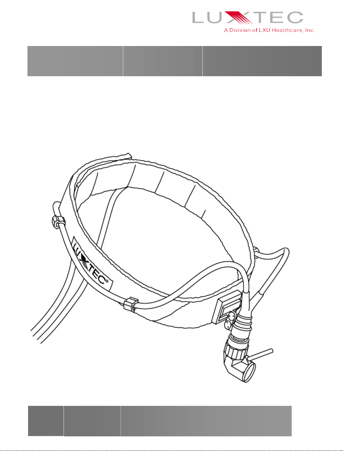
UltraLite Headlight Operation
and Service Manual
ENGLISH
Page 2

TABLE OF CONTENTS
p
Indication for Use 2 Care and M aintenan ce 6
Gener a l Wa r n in gs
Assembl y
Adju s tments
Replacement Part Numbers
2 Troubleshooting 6
3-4 Lu xtec Equip m ent Warra nty 7
4-5 Lu xtec C able Warra nty 7
5 Repair and Return 7
INDICATION FOR USE
This fiber optic light guide system is designed
to deliver illumination from a high intensity
light source to a surgical headlight for surgical
site illumination, either standard or minimally
invasive. While the cable light source
endfittings are compatible with all light
sources, brightness and spot quality vary with
specific types of light sources. The xenon
GENERAL WARNINGS
The user of this product should be thoroughly familiar
and trained in the use and care of this product.
The user should carefully study this manual before
making any attempt to use the product clinically.
Instructions should be followed specifically, with
special attention given to warnings and cleaning
instructions. This manual should also be availa ble to
the surgical team during a procedure.
Follow the instructions in the operating manuals of
other manufacturer’s equipment when they are use in
conjunction with this product.
Before every procedure, carefully inspect the light
guide cable to ensure it has been properly maintained,
cleaned and sterilized (if compatible), and that it is
fully functional.
Any light source used with this cable should have a
maximum output of 0.25W IR at the cable port to
revent cable and/or headlight damage during use.
UltraLite systems perform best with Luxtec
xenon light sources.
Any light source used with this cable should
have a maximum output of 0.25W IR at the
cable port to prevent cable and/or headlight
damage during use.
Light sources use high intensity lamps, which
produce heat as well as brilliant light. The high
brightness produced by the light source and the light
output of the light guide cable can cause burns.
Care should be taken to follow the maintenance and
cleaning instructions. Excessive bending of the cable
should be avoided.
Use care not to point the light guide directly at the
eye while in operation. The brilliant light output can
cause severe eye discomfort.
FIRE HAZARD: DO NOT DRAPE OR
COVER THE LIGHT SOURCE OR THE
LIGHT GUIDE WHILE IT IS OPERATING.
DO NOT PLACE THE LIGHT GUIDE ON A
DRAPE WHILE IT IS OPERATING.
CAUTION: The metal portions of the cable at
the light source get hot during operation.
Allow components to cool outside of the light
source for at least 5 minutes before touching.
2
Page 3
ASSEMBLY OF HEADLIGHT SYSTEMS
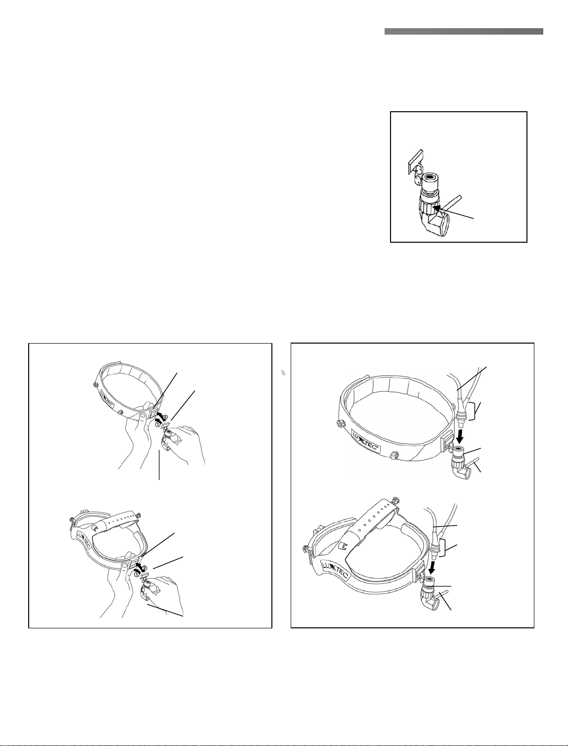
The Luxtec headlight assembly consists of a headlight with a variable spot module, a cushioned headband or
sweatband, bifurcated fiber optic cable and two gown clips.
To assemble, attach the headlight module by sliding the bottom of the
module clip into the module receptacle, then push the top in until it makes
an audible ”snap” (Figure 1). To attach the joystick, thread it into the
hole in the front of the headlight module.
To attach the fiber optic cable, insert the angled end of the cable into the
headlight module until it snaps into place (Figure 2). A bifurcated cable
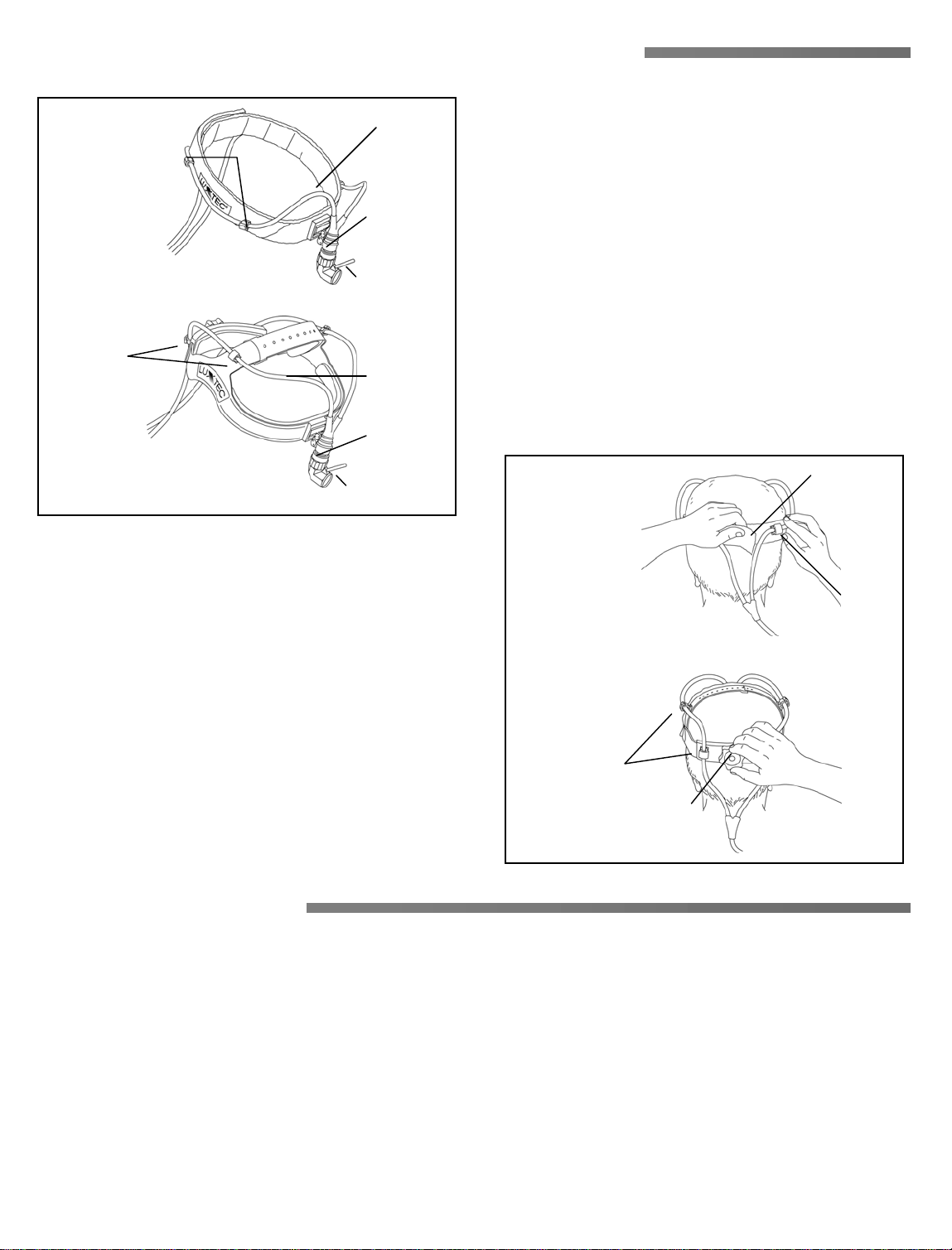
fits into the cable clips on both sides and the rear of the headband or
sweatband (Figure 3).
Remove the cable from the module by grasping the body of the module in one hand and the lower-most ridges of the
cable in the other hand and pulling them axially apart. Do not hold the cable by its leg(s) or strain relief.
Figure 1a
Ultralite
Module
P/N 00-1190
Iris
Adjustment
Figure 1
SWEATBAND
(properly supported)
HEADBAND
(properly supported)
Module receptacle
Insert bottom first,
then snap in top
Headlight module
Module receptacle
Insert bottom first,
then snap in top
Headlight module
Figure 2
SWEATBAND
HEADBAND
Fiber optic
cable
Grasp cable
here for
installation
and removal
Headlight
module
Joystick
Fiber optic
cable
Grasp cable here
for installation
and removal
Headlight
module
Joystick
Remember, the cable is made of glass fibers. When adjusting the cable on the headband, do no bend the
cable more than 60 degrees. The cable is designed to curve gently around the shape of the headband.
All illustrations are representative and may not reflect your actual model and accessories.
3
Page 4
ASSEMBLY OF HEADLIGHT SYSTEMS
N
Figure 3
SWEATBAND
Cable
Clips
HEADBAND
Cable
Clips
Fiber
optic
cable
Headlight
module
Joystick
Fiber
optic cable
Headlight
module
Joystick
ext, place the headband or sweatband on your head.
You can make size adjustments on the headband by
turning the knob at the rear of the headband until it fits
comfortably. The cross band can be adjusted for even
more comfort. Push out the tab and slide the band until
the fit is correct, then replace the tab. The sweatband
should be pulled to a comfortable tension and closed
using the velcro strip
(Figu re 4).
To remove the module from the headband or
sweatband, a small screwdriver is needed. Insert the
screwdriver into th e slot at th e top of the mod u le
receptacle. Lift the handle of the screwdriver and the
modu le will sl id e out.
Figure 4
SWEATBAND
Velcro
strip
Caution:
Cable
Clip
To plug or unplug the fiber optic cable from the
light source, it is recommended that the light
source power be turned off. Be sure to hold the
HEADBAND
strain reliever near the end of the cable. This
part of the cable is reinforced to prevent damage
to th e glass fi bers in si de, and t o prevent bu rns.
Cable
Clips
Adjusting knob
ADJUSTMENTS
Once the headlight module and fiber optic cable are attached to the headband, the headlight assembly is ready to use.
The headlight module can be adjusted while wearing the headlight system by grasping the joystick. The joystick can
be removed for autoclaving or to prevent misaligning the headlight module when working in close quarters. The iris
adjustment varies the spot size from 20mm to 100mm (0.8 to 4 inches) at a 40 cm (16 inch) working distance
(Figure 1a).
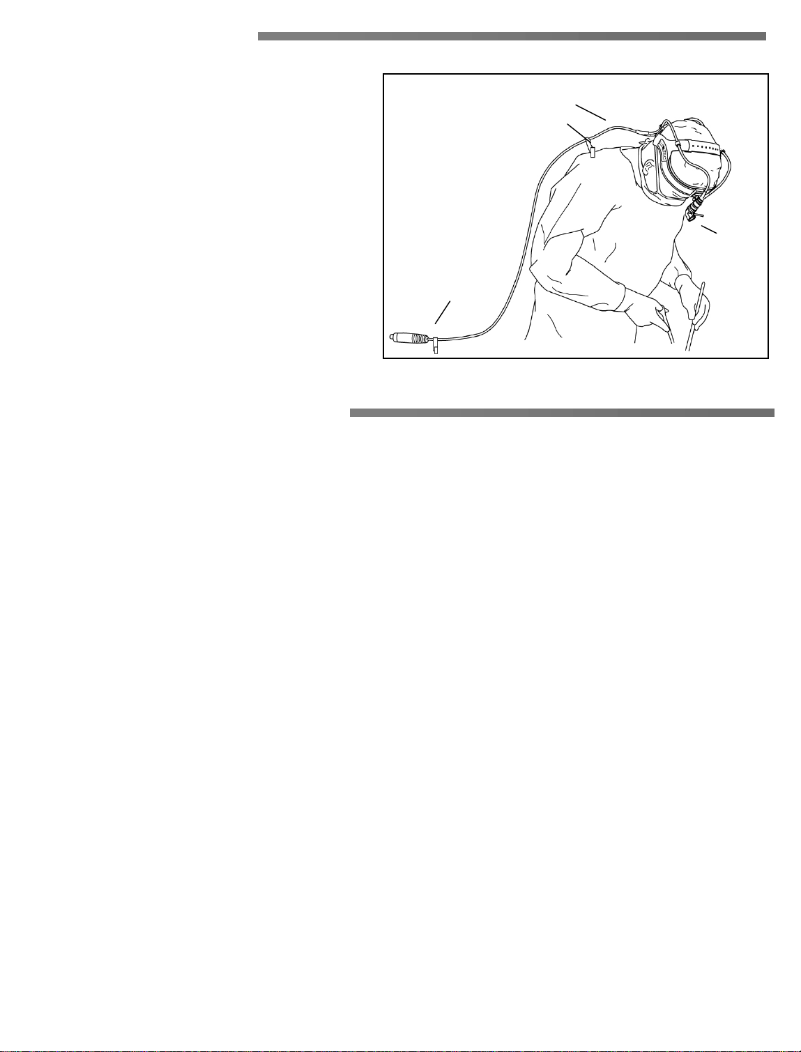
The headlight system comes with two gown clips to relieve the weight of the cable from the headband. The upper clip
is attached to the surgical gown just below the shoulder (Figure 5). Be sure to leave enough slack in the cable to
allow for freedom of head movement. If the surgeon needs to detach the cable from the light source, the lower gown
clip is used to attach to the surgeon’s gown. This eliminates the risk of dropping or tripping over the cable.
4
Page 5
ADJUSTMENTS
CAUTION: The metal portions of the cable at the
light source get hot during operation. Allow
components to cool ou ts id e of the ligh t sou r ce for
at least 5 minutes before touching.
Luxtec manufactures its headlights to the highest
quality standards. Each one is tested thoroughly
before leaving the factory to ensure proper working
conditions.
These instructions should help you get started with
your new Luxtec equipment, quickly and easily. If
you have any problems, please contact the Luxtec
Service Department, (800) 325-8966, or
(508) 835-9700, Fax (508) 835-9976.
Figure 5
Lower gown clip
Slack (fiber optic cable)
Upper gown clip
REPLACEMENT PARTS
Part Number Description
AX-1375-BIF Headband with Ultralite 2 bifurcated cable, Ultralite module and extended linkage
AX-1385-BIF Sweatband with Ultralite 2 bifurcated cable, Ultralite module and extended linkage
Joystick
AX-1375-BIF-SL Headband with Ultralite 2 bifurcated cable and Ultralite module
AX-1385-BIF-SL Sweatband with Ultralite 2 bifurcated cable and Ultralite module
AX-1175-BIF Headband with bifurcated cable, Ultralite module and extended linkage
AX-1185-BIF Sweatband with bifurcated cable, Ultralite module and extended linkage
AX-1175-BIF-SL Headband with bifurcated cable and Ultralite module
AX-1185-BIF-SL Sweatband with bifurcated cable and Ultralite module
00-1170-BIF Replacement headband for AX-1175-BIF or AX-1175-BIF-SL
00-1190 Module (gray)
00-1190-EL Module (gray) with extended linkage
00-1270-BIF Replacement headband for AX-1375-BIF or AX-1375-BIF-SL
00-1290 Sweatband for bifurcated cable
00-1290-BIF Replacement sweatband for AX-1375-BIF or AX-1375-BIF-SL
00-2300-9 Replacement cable bifurcated (add –G for gray cable)
00-2900-9 Ultralite 2 bifurcated cable
400282 Replacement kit pad for headband
400286 Joystick for 00-1190, pack of 3
5
Page 6

CARE AND MAINTENANCE
p
p
All Headlight Systems :
To ensure long life for the headband, cable, and
modules, they should be stored in the duffel bag or
case provided. Fiber optic cables are fine, high
quality optical instruments. You can prolong the
useful life by following a few guidelines:
Avoid stretching your cable, forming
•
configurations involving sharp angles or kinks,
or contact with sharp or pointed objects. The
internal light fibers are made of glass, a material
which breaks under stress. Fiber breakage will
result in diminished light output.
Utilize the gown clips (If provided) to keep the
•
headlight cable secured to the surgeon’s gown
for greater comfort and maneuverability. (This
does not include endoscopic use)
Do not use your fiber optic cable with any
•
alterations to it’s original design or fabrication.
Bundle size (aperture) of the fiber optic cab le
should be matched to the aperture of the
instrument to obtain maximum light output.
NOTE: A larger aperture fiber optic cable will
•
not increase light output of a smaller aperture
instrument.
Keep the optical faces from contacting the floor
•
or other hard surfaces. The resulting scratches
will diminish light output. Store the cables in
sterilization tray s for addit i onal pro tec tion.
Any inadvertent cut or puncture to the silicone
•
tube will render the cable unsafe. It should be
taken out of service immed iate ly .
Cleaning Modules:
The headlight module may be wiped down with
alcohol. The lens should be cleaned only with lens
tissue available at any camera store. Follow the
ackage directions.
Follow all applicable bloodborne pathogen cleaning
rocedures as indicated by OSHA and / or your
hospital requirements when cleaning, disinfecting,
and sterilizing instruments and accessories.
Cleaning Joystick (only):
The joystick can be removed from the module for
autoclaving.
Cleaning Sweatband:
The sweatband may be cleaned using standard wash
cycles in warm water and detergent. Air dry.
Cleaning Headband:
The headband may be cleaned by an alcohol
wipedown or washed with lukewarm water and mild
detergent. Rinse thoroughly with water.
Cleaning Cable:
Luxtec suggests that the use of alcohol wipes to
clean the UltraLite and Sweatband headlight cables.
Disinfecting Cable:
Soaking the UltraLite 2 cables in any sterilizing
disinfectant should be avoided. There is a lens
assembly at the light source end, which is not sealed
and could allow moisture to penetrate behind the
lensing.
Sterilizing Cable:
The UltraLite fiber optic cable has not been
specifically designed to withstand sterilization.
There is a lens assembly at the light source end,
which is not sealed and could allow moisture to
penetrate behind the lensing.
WARNING: Do not autoclave the headband,
cables, sweatband or headlight modules.
TROUBLESHOOTING
For additional technical assistance, please contact the Luxtec Service Department at 1-800-325-8966
(USA only) or +1-508-835-9700, Fax +1-508-835-9976 or email: [email protected]
6
Page 7

LUXTEC HEADLIGHT WARRANTY
p
r
•
I
Luxtec warrants that the equipment manufactured by
Luxtec shall be free from defects in material and
workmanship under normal use and service for a
eriod of eighteen (18) months from the date of
shipment from Luxtec. Luxtec’s sole and exclusive
liability under warranty shall be, at Luxtec’s option,
either to repair or replace any com ponent which fa ils
during the warranty period due to any defect in
workmanship or material F.O.B. factory if:
1. Customer promptly reports such defect to
Luxtec in writing,
2. If requested by Luxtec, customer returns
equipment to Luxtec with shipping charges and,
3. Upon inspection, Luxtec finds the equipment to
be defective.
LUXTEC CABLE WARRANTY
LUXTEC warrants that the cables fur n ished hereunde
shal l be fr ee from defects in material and workmanship
under normal use and service for a period of eighteen (18)
mon t hs from the date of shipment from LUXTEC.
LUXTEC’s sole and exclusive liability under this warranty
shal l be, at LUXTEC’s option, either to repair or r epl ace
any components of th e cable which fai ls during the
warranty period due to workmanship or material F.O.B.
fact ory if:
1. Customer promptly reports su ch a defect to
LUXTEC in writi ng,
2. If reques ted by LUXTEC, customer returns
equipment to LUXTEC with shipping charges prepaid and,
3. Upon inspection , LUXT E C finds the ca ble to be
defective.
This warr anty is contingent upon n or m al and proper us e of
the cabl e and does not cover:
Fiber Breakage,
•
Soaking of cable l ens in sterilizin g disin fe ctant , or
•
autoclaving,
A cable which has been modified without the written
•
approval of LUXTE C ,
This warranty is contingent upon normal and proper
use of the equipment. It does not cover equipment
modified without the written approval of Luxtec,
subjected to unusual physical or electrical stress, or
damaged during shipment. This warranty is nontransferable unless authorized in writing by Luxtec.
Luxtec reserves the right to make design changes on
its products without liability to incorporate said
change in Luxtec products previously designed or
sold.
Upon receipt of the product, it should be carefully
inspected. If any defect is discovered, notification
must immediately given to the manufacturer.
A cable that has been subjected to unusual physica l
stress, or
A cable that was damaged during shipment.
•
This warranty is non-transferable unless authorized in
writing by LUXTEC.
If LUXTEC i s un able to remed y any defect in the cable as
required by the foregoing warranties, LUXTEC’s liability
shall in no event exceed the purchas e price received
hereunder by LUXTEC for the equipment.
THE WARRANTIES SET FORTH HEREIN ARE IN
LIEU OF ANY OTHER REPRESENTATIONS OR
WARRANTIES. LUXTEC DISCLAIMS AND
CUSTOMER WAIVES ALL OTHER EXPRESS OR
IMPLIED WARRANTIES, INCLUDING BUT NOT
LIMITED TO, ALL IMPLIED WARRANTIES OR
MERCHANTABILITY AND FITNESS FOR A
PARTICULAR PURPOSE. IN NO EVENT SHALL
LUXTEC BE LIABLE TO ANY PARTY FOR
INDIRECT, INCIDENTAL OR CONSEQUENTI AL
DAMAGES, WHETHER RELATED TO THIS OR ANY
OTHE R CLAIM, REGARD LESS OF ANY
KNOWLEDGE OF LUXTEC OF SUCH POTENTIAL
DAMAGES.
REPAIR AND RETURN
Any device must be clean when returned to
LUXTEC. LUXTEC reserves the right to return
unrepaired any equipment that is contaminated with
blood or other organic material.
Warranty Service and Repair:
Copyright 2001 LUXTEC Corporation. All rights reserved. No part of this manual may be copied or reproduced
without written permission of LUXTEC Corporation. Printed in the U.S.A. Violations will be prosecuted.
nformation contained in this manual is subject to change without notice.
To obtain service under warranty or return product
for repair, the customer should contact the local
LUXTEC distributor or call LUXTEC Customer
Service at 1-800-325-8966 (USA only) or
+1-508-835-9700.
7
Page 8
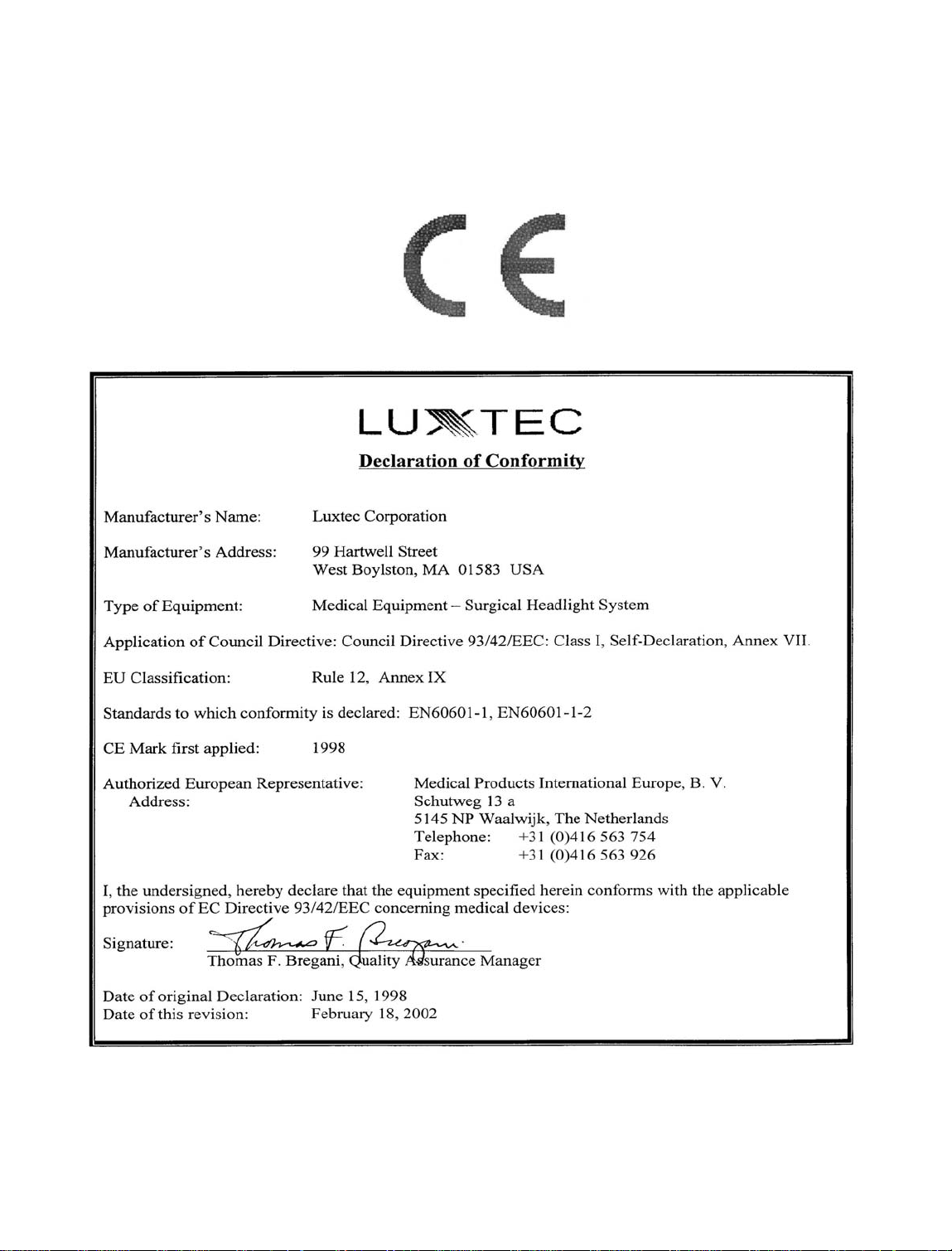
Luxtec Corporation declares that this product meets the
Essential Requirements specified in Annex 1
of the Medical Device Directive (MDD).
99 Hartwell Street • West Boylston, MA 01583 • USA
Telephone: 1-800-325-8966 US only or +1-508-835-9700
Facsimile: +1-508-835-9976 E-mail address: [email protected]
P/N 850185L
 Loading...