

Page 1
www.allstarlighting.com
LR34190, LR34191, LR34192, LR34193, LR34194T8 4’
INSTALLATION GUIDE
IMPORTANT SAFETY INSTRUCTIONS
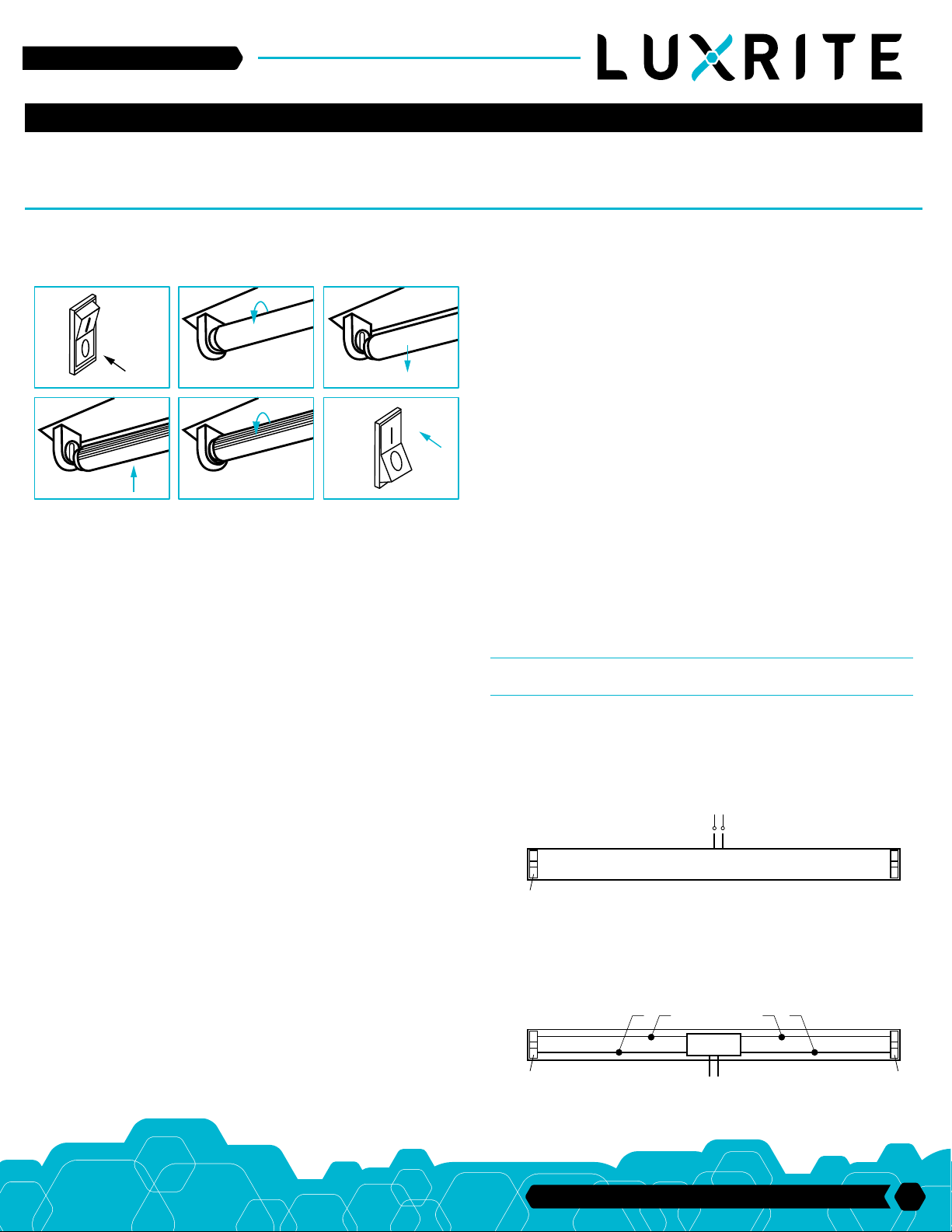
For direct replacements for specific fluorescent lamps (32W/48T8,
30W/48T8, 28W/48T8, 25W/48T8), please follow steps below:
OFF
Fluorescent Lamp
1
LED T8
LED T8
4
1. Switch-off power to the luminaire.
2. Remove diffuser (if provided)
3. Remove the existing fluorescent lamps from the luminaire.
4. Install the LED T8 replacement lamp
5. Replace diffuser (if removed in Step 2)
6. Switch-on power to the luminaire.
2
5
TO USE AS LED LUMINAIRE CONVERSION RETROFIT KIT
DANGER - RISK OF SHOCK - DISCONNECT POWER BEFORE
INSTALLATION.
THE RETROFIT KIT INCLUDES INSTALLATION INSTRUCTIONS, LED LAMP,
LUMINAIRE MARKING LABELS.
THE T8 LED TUBES ARE INTENDED TO RETROFIT LISTED SURFACE
MOUNTED, TYPE NON-IC OR TYPE IC RECESSED MOUNTED FLUORESCENT LUMINAIRES WITH OR WITHOUT DIFFUSER FOR A MAXIMUM OF
FOUR LAMPS WITH A MINIMUM DISTANCE OF 11 CM BETWEEN LAMPS; PR
RETROFIT SURFACE MOUNTED LISTED FLUORESCENT LUMINAIRES
WITHOUR DIFFUSER FOR A MAXIMUM OF SIX LAMPS WITH A MINIMUM
DISTANCE OF 5.5 CM BETWEEN LAMPS.
Fluorescent Lamp
3
ON
6
tion requires knowledge of luminaire electrical systems. If not qualified, do not
attempt installation. Contact a qualified electrician.
WARNING - RISK OF FIRE OR ELECTRIC SHOCK: Install this kit only in the
luminaires that have the construction features and dimensions shown in the
photographs and/or drawings and where the input rating of the retrofit kit does
not exceed the input rating of the luminaire.
WARNING - To prevent wiring damage or abrasion, do not expose wiring to
edges of sheet metal or other sharp objects.
DO NOT MAKE OR ALTER ANY OPEN HOLES IN AN ENCLOSURE OF
WIRING OR ELECTRICAL COMPONENTS DURING KIT INSTALLATION.
Installers should not disconnet existing wires from lamp holder terminals to
make new connections at lamp holder terminals. Instead installers should cut
existing lamp holder leads away from the lamp holder and make new electrical
connections to lamp holder lead wires by employing applicable connectors.
THIS RETROFIT KIT IS ACCEPTED AS A COMPONENT OF A LUMINAIRE
WHERE THE SUITABILITY OF THE COMBINATION SHALL BE DETERMINED
BY AUTHORITIES HAVING JURISDICTION.
DO NOT USE WITH DIMMERS
RISK OF ELECTRIC SHOCK - USE IN DRY AND DAMP LOCATIONS ONLY
THIS DEVICE IS NOT INTENDED TO BE USED WITH EMERGENCY EXITS
RETROFIT FLUORESCENT LUMINAIRE WITH ELECTRONIC
BALLAST
STEP 1: Shut off power before work
STEP 2: Remove existing fluorescent tube(s), diffuser (if applicable) and
open the ballast cover.
STEP 3: Disconnect luminaire supply wirings L and N to branch circuit as
shown in FIG. 1
FIG. 1
Branch Circuit
L N
Luminaire
THE PRODUCTS ARE INTENDED TO BE USED IN DRY AND DAMP LOCATIONS ONLY.
THIS PRODUCT MUST BE INSTALLED IN ACCORDANCE WITH THE
APPLICABLE INSTALLATION CODE BY A PERSON FAMILIAR WITH THE
CONSTRUCTION AND OPERATION OF THE PRODUCT AND THE
HAZARDS INVOLVED.
WARNING - RISK OF FIRE OR ELECTRIC SHOCK: The electrical rating of
these products is 120-277V, the installer must determine whether they have
120-277V at the luminaire before installation.
WARNING - RISK OF FIRE OR ELECTRIC SHOCK: LED Retrofit Kit installa-
Lampholder
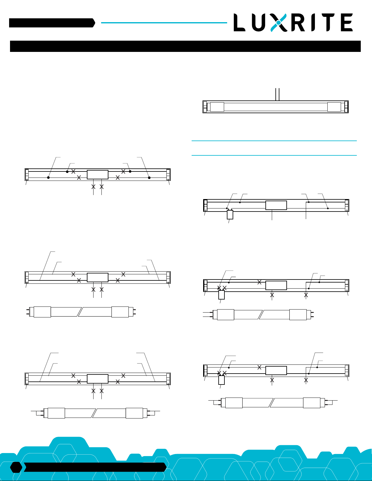
STEP 4: Original circuit as shown in Fig. 2. Cut lampholder leads “1,2,3,4, L,
N”, then check whether the lampholder is shunted. Cut as far away from the
lampholders to allow for longer lengths of wire at both lampholders. Note:
Ballast must be retained in place.
FIG. 2
Lampholder
1 2 43
BALLAST
N L
Lampholder
33 Randolph Ave. • Avenel NJ 07001 | 732-882-1500
1
Page 2
www.allstarlighting.com
INSTALLATION GUIDE
STEP 5: Check the lampholders. If the lampholders ar shunted, go to Step 6.
If the lampholders are not shunted, go to Step 7. For “One End” wiring configuration only, “WARNING: To avoide potential fire or shock hazard, do not use
this retrofit kit in luminaires employing shunted bi-pin lampholders. Note:
Shunted lamp holders are found only in fluorescent luminaires with
Instant-Start ballasts. Instant-start ballasts can be identified by the words
”Instant Start” or “I.S” marked on the ballast. This designation may be in the
form of a statement pertaining to the ballast itself, or may be combined with
the marking for the lamps with which the ballast is intended to be used, for
example F40T12/IS. For more information, contact the LED luminaire retrofit
kit manufacturer.”
STEP 6: If the lamp holders are shunted, connect one lead from each
lampholder to branch circuit as follows, “Leads 3 and 4” connected to L;
“Leads 1 and 2” connected to N as shown in Fig. 3.
FIG. 3
Lampholder
1
N
2
N
BALLAST
N L
L
4
L
3
Lampholder
STEP 7: The lampholders are not shunted. “One End” or “Both End” wiring
can be selected. For “One End” wiring, connect one lead from each lampholder to branch circuit as follows, “Leads 1” connected to L; “Leads 2” connected
to N. Don’t connect Lead 3, Lead 4 to the circuit as shown in Fig. 4. Note: Leads
1 and Leads 2 are respectively connected to L and N1 on the LED tube, don’t
connect N2 and N3 in the circuit.
FIG. 4
Lampholder
L
N1
Connect to
1
branch circuit L
2
Connect to
branch circuit N
BALLAST
N L
Don’t connect
to branch circuit
4
3
Don’t connect
N2
to branch circuit
N3
Lampholder
STEP 8: Attach the field applied label to the luminaire. Install ballast cover
and diffuser (if applicable) back on Luminaire, and T8 LED tube as shown in
Fig. 5
FIG. 5
L N
T8 LED Tube
STEP 9: Turn on the AC power source, LED Tube will light.
THE WIRING OF MULTIPLE LAMPS IS THE SAME AS ABOVE.
RETROFIT FLUORESCENT LUMINAIRE WITH SEPARATE
STARTER AND MAGNETIC BALLAST
REPEAT STEPS 1 TO 3
STEP 4: Original circuit as shown in Fig. 6. Cut lampholder leads “1,2,3,4”, cut
as far away from the lampholders to allow for longer lengths of wire at both
lampholders. Note: Ballast must be retained in place.
FIG. 6
Lampholder
STEP 5: “One End” or “Both End” wiring can be selected. For “One End” wiring,
connect one lead from each lampholder to branch circuit as follows, “Leads 1”
connected to L; “Leads 2” connected to N. Don’t connect Lead 3, Lead 4 to the
circuit as shown in Fig. 7. Note: Leads 1 and Leads 2 are respectively connected
to L and N1 on the LED Tube, Don’t connect N2 and N3 in the circuit.
FIG. 7
Lampholder
L
N1
Starter
Starter
1
2
Connect to branch circuit L
1
Connect to branch circuit N
2
3
BALLAST
N L
BALLAST
N L
4
3
4
N2
N3
Lampholder
Don’t connect
to branch circuit
Lampholder
Don’t connect
to branch circuit
For “Both Ends” wiring, Connect one lead from each lampholder to branch
circuit as follows, “Leads 1 and Leads 2” connected to L; “Leads 3 and Leads 4”
connected to N as shown in Fig. 4A
FIG. 4A
Lampholder
1
Connect to
branch circuit L
2
Connect to
branch circuit N
BALLAST
N L
L
2
33 Randolph Ave. • Avenel NJ 07001 | 732-882-1500
3
4
Lampholder
N
For “Both Ends” wiring, Connect one lead from each lampholder to branch
circuit as follows, “Leads 1 and Leads 2” connected to L; “Leads 3 and Leads 4”
connected to N as shown in Fig. 7A
FIG. 7A
Lampholder
L
Starter
1
Connect to
2
branch circuit L
BALLAST
N L
3
Connect to
branch circuit N
4
Lampholder
N
REPEAT STEPS 8 AND 9
THE WIRING OF MULTIPLE LAMPS IS THE SAME AS ABOVE.
 Loading...