

Page 1
www.allstarlighting.com
INSTALLATION GUIDE
2’, 3’, 4’, 8’ 3 CCT CHANGE LINEAR FIXTURE
LR25161, LR25163, LR25165, LR25167
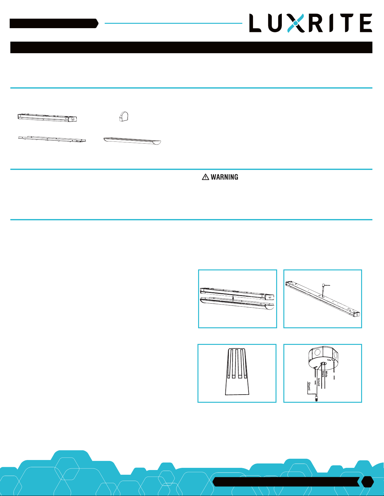
PACKAGING CONTENTS
A. FIXTURE CHANNEL
C. CHANNEL COVER WITH LEDS
NOTE: This product is intended for either single mount or
continuous row applications
B. DECORATIVE END CAPS
D. LENS ASSEMBLY
ITEMS REQUIRED
• Stud mount (2) 1 1/2in. long #8 or larger wood screws and a #10 flat washer
• Drywall mount (2) 3in. long 3/16” or larger diameter toggle bolt and #10 flat
washer (if joist cannot be located)
• Phillips screwdriver
• Flat head screwdriver
• Pliers
• Hammer
• Safety glasses
• Ladder
(PURCHASE SEPARATELY)
IMPORTANT SAFETY INSTRUCTIONS
When using product, basic precautions should always be followed, including the
following:
• Read and follow these instructions
• Heed all warnings, including below warnings AND those included on product.
• Save these instructions and warnings
• Risk of fire/electric shock
• Ground fixture to avoid potential electric shock
• Turn off the power at fuse or circuit breaker box before installation and
maintenance
• Edges may cut. Handle with care
CAUTION
• The fixture is connected to 120-277V, 50Hz or 60Hz power source
• Fixture should be installed by persons with experience wiring or by a qualified electrician. The electrical system, and the method of electrically connecting
the fixture to it, must be in accordance with the National Electrical Code and local building codes.
INSTALLATION INSTRUCTIONS
1. Turn off the power at the main fuse/breaker box. Carefully open carton,
remove fixture and end caps from carton.
2. To remove the channel cover with the LED’s from the main channel body
squeeze beneath the embossed locking tabs on the main channel body and
lift on the channel cover with LED’s. Do this for all 6 locking tab locations
(Fig. 1). The channel cover with LED’s can be placed in safe location until
fixture is mounted.
3. Remove appropriate knockout(s) for power supply wiring. To remove,
simply place a flathead screwdriver on the knockout and strike it sharply
with a hammer (Fig. 2) The slug may then be removed with pliers.
4. Connect L/N wire using supplied wire nut (Fig. 3)
5. Prepare the supply wires.
A. Wiring must comply with all applicable electrical codes.
B. Strip wire to 3/8” (9.5mm). (Fig. 3)
6. Attach junction box cover plate and pull wire through junction box. (Fig. 4)
NOTE: SEE ROW MOUNTING SECTION IF ROW MOUNTING BEFORE
CONTINUING TO STEP 7
FIG. 1 FIG. 2
FIG. 3 FIG. 4
33 Randolph Ave. • Avenel NJ 07001 | 732-882-1500
1
Page 2
www.allstarlighting.com
INSTALLATION GUIDE
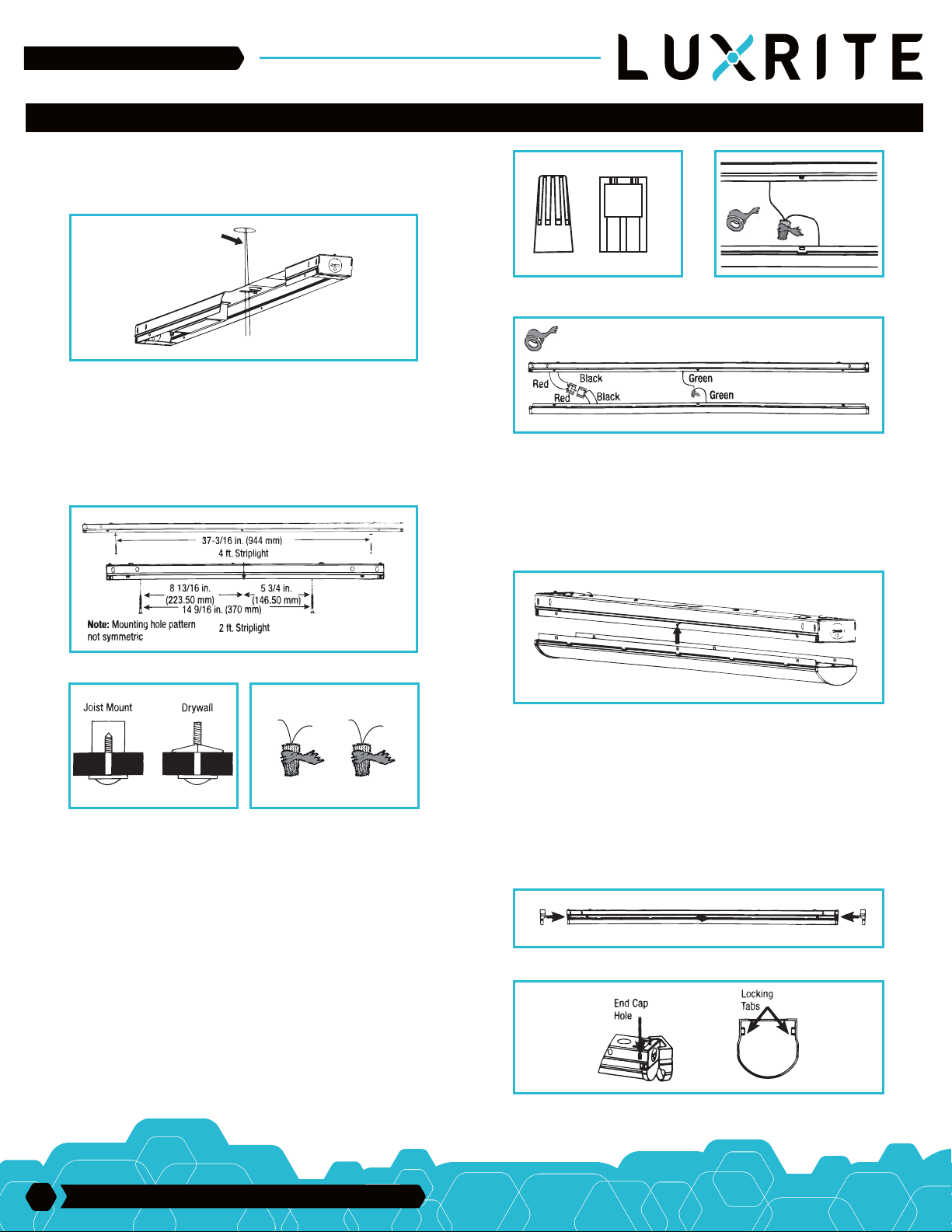
7. Locate power supply wires from the junction box and pull them through
the knockout that has been removed on the main channel body so that the
wires and disconnect are inside the housing channel (Fig. 5)
FIG. 5
8. Attach main housing channel to ceiling or wall using #8 or larger diameter
wood screws plus #10 flat washer for stud mount or 3/16” diameter or larger
toggle bolt plus #10 flat washer for drywall mounting. The spacing for
mounting brackets is 37-3/16” for 4’ fixture or 14 9/16” for 2’ fixture. (Fig. 6&7)
NOTE: 2’ FIXTURE MOUNTING HOLE PATTERN IS NOT SYMMETRIC
FIG. 9A FIG. 9B
FIG. 9C
11. Tuck all the excess supply wire, orange inline connectors, and the quick
disconnect back into the main channel housing.
FIG. 6
L
N
L
N
FIG. 7 FIG. 8
9. Connect junction box and driver using supplied wire nut. Black to black and
white to white. (Fig. 8)
10. Locate the channel cover with LEDs and provided lead wires to make connections to the driver output wires and ground wire. To properly engage wires, firmly
push wire leads into the orange in-line connector attached to the driver output
leads. Connect the black lead on the cover with the black lead on the driver.
Then, connect the red lead on the cover with the red lead on the driver. Lastly,
connect the green lead on the cover with the green ground lead on the housing
channel. For fixtures wirh 2 drivers connect the second set of black and red wires
to the channel cover with LEDs. Black to black and red to red. (Fig. 9A, 9B & 9C)
12. Mechanically attach the channel cover with LEDs back to the housing
channel by sliding the Channel cover with LEDs holes onto the locking tabs on
the main housing channel (Fig. 10), Remove protective film from the lens.
FIG. 10
13. Optional: Attach decorative end caps by placing the end cap’s locking
tabs over the ends of the fixture and sliding towards the center of the fixture
until both the locking tabs snap into end cap holes on main housing (Fig.
11A & 11B).
NOTE: DECORATIVE END CAPS CANNOT BE PLACED BETWEEN TWO
FIXTURES WHICH HAVE BEEN ROW MOUNTED TOGETHER. FOR
NOW MOUNTING DECORATIVE END CAPS CAN ONLY BE PLACED ON
FAR ENDS OF FIXTURE.
FIG. 11A
NOTE: FOR DIMMING SEE INSTALLING DIMMER INSTRUCTION
SECTION
2
33 Randolph Ave. • Avenel NJ 07001 | 732-882-1500
FIG. 11B
Page 3
www.allstarlighting.com
INSTALL ATION G U I D E
ROW MOUNTING
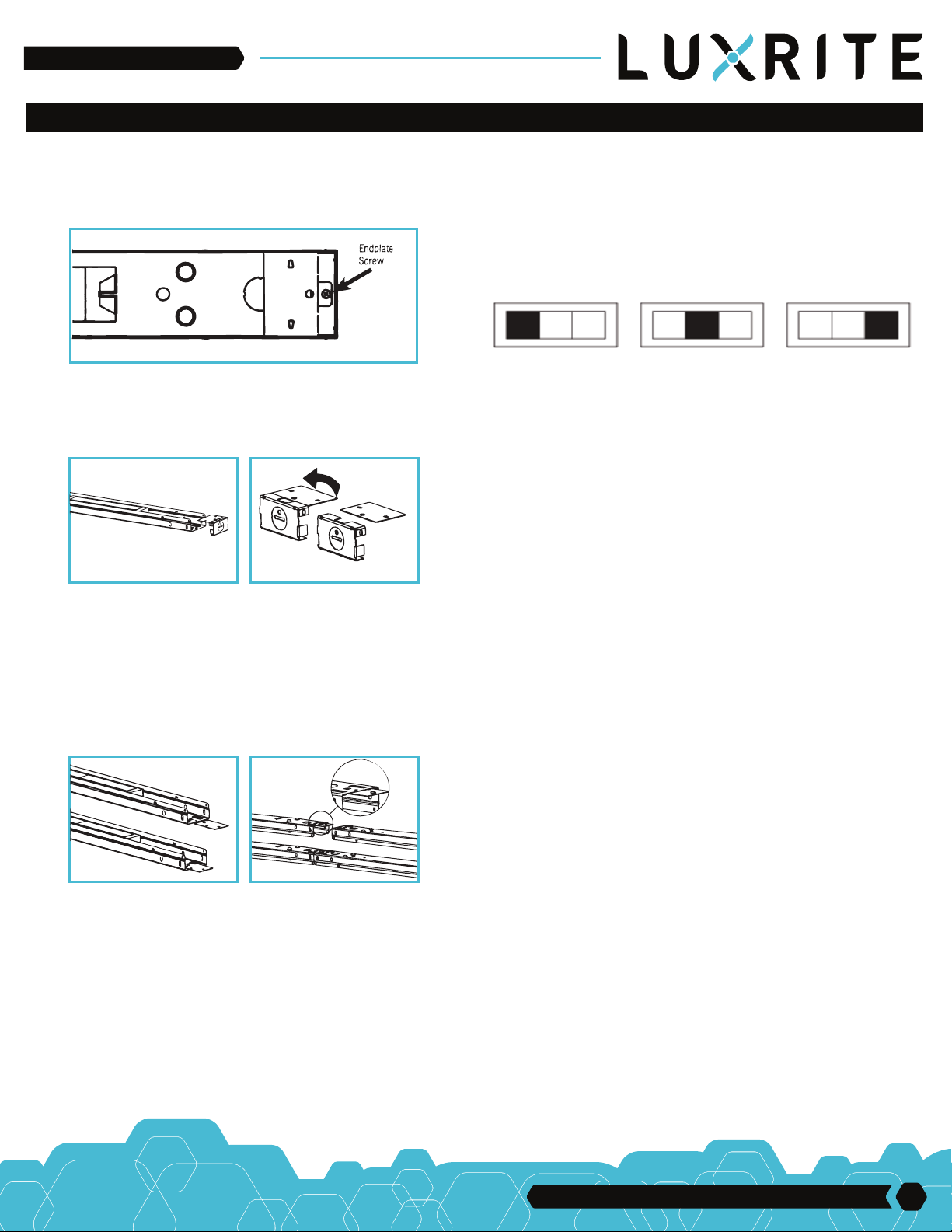
1. For row mounting locate the metal end plate at the end of the fixture of
the main channel body which you plan to remove. Remove the end plate
screw from the metal end plate (Fig. 12). Repeat for adjacent fixture.
FIG. 12
2. Squeeze the main channel housing to release the locking tabs on the
metal end plate and remove the metal end plate from main channel
housing (Fig. 13). Repeat for adjacent fixture.
FIG. 13 FIG. 14A
3. Using one of the metal end plates which you just removed break away the
row mounting tab by bending the end plate. A few maximum bens may be
required to completely break away the tab (Fig. 14A)
COLOR TEMPERATURE SETTING
ADJUSTMENT
Adjust CCT switches on each board accordingly to the desired color
temperature as seen below. All boards must be set the same way. Power to
fixture must always be turned OFF prior to adjusting CCT switch.
NOTE: FIXTURE IS PRESET TO 3000K FROM FACTORY
3000K 4000K 5000K 3000K 4000K 5000K
*This LUXRITE fixture, when properly installed and under normal
conditions of use, is guaranteed to be free from defects in materials for
three years from date of sale.
3000K 4000K
5000K
4. Using the mounting tab from the metal end plate insert it into the slots
provided at the end of the main channel housing (Fig. 14B). Ensure locking
tabs are facing the locking tab hole provided in the main housing body.
Slide row mounting tab into slot until an audible click is heard (Fig. 14C)
FIG. 14B FIG. 14C
5. Mount the first fixture with row mounting tab following steps 7-12 above.
6. To install second fixture side fixture over row mounting tab (Fig. 14C) and
follow steps 7-12 above.
33 Randolph Ave. • Avenel NJ 07001 | 732-882-1500
3
 Loading...