

Page 1
www.allstarlighting.com
INSTALLATION GUIDE
4” J-BOX DOWNLIGHT
LR24840, LR24841, LR24842, LR24843
PLEASE READ CAREFULLY AND SAVE THESE INSTRUCTIONS, AS YOU MAY NEED THEM AT A LATER DATE.
REMOVE THE TRIM FROM THE BOX AND MAKE SURE THAT NO PARTS ARE MISSING. THIS RETROFIT ASSEMBLY IS ACCEPTED AS A COMPONENT OF A LED
LUMINAIRE WHERE THE SUITABILITY OF THE COMBINATION SHALL BE DETERMINED BY CSA OR CANADIAN AUTHORITIES HAVING JURISDICTION.
WARNING - RISK OF FIRE OR ELECTRIC SHOCK
DISCONNECT MAIN POWER AT FUSE OR CIRCUIT BREAKER BEFORE INSTALLING OR SERVICING THE FIXTURE.
• DO NOT MAKE OR ALTER ANY OPEN HOLES IN AN ENCLOSURE OF WIRING OR ELECTRICAL COMPONENTS DURING KIT INSTALLATION.
• TO PREVENT WIRING DAMAGE OR ABRASION, DO NOT EXPOSE WRING TO EDGES OF SHEET METAL OR OTHER SHARP OBJECTS.
• SUITALBE FOR TYPE IC OR SUITABLE FOR TYPE NON-IC
• USE ONLY IN OPEN LUMINAIRES
• THIS DEVICE IS NOT INTENDED FOR USE WITH EMERGENCY EXITS
ASSEMBLY AND INSTALLATION
This IC/AT fixture is intended for use in recessed cavities or suspended ceilings (with or without insulation). Choose the location for the fixture, taking into
consideration the location of the joists, the 5-6 in. depth clearance and electrical supply.
• SHUT OFF POWER BEFORE INSTALLATION
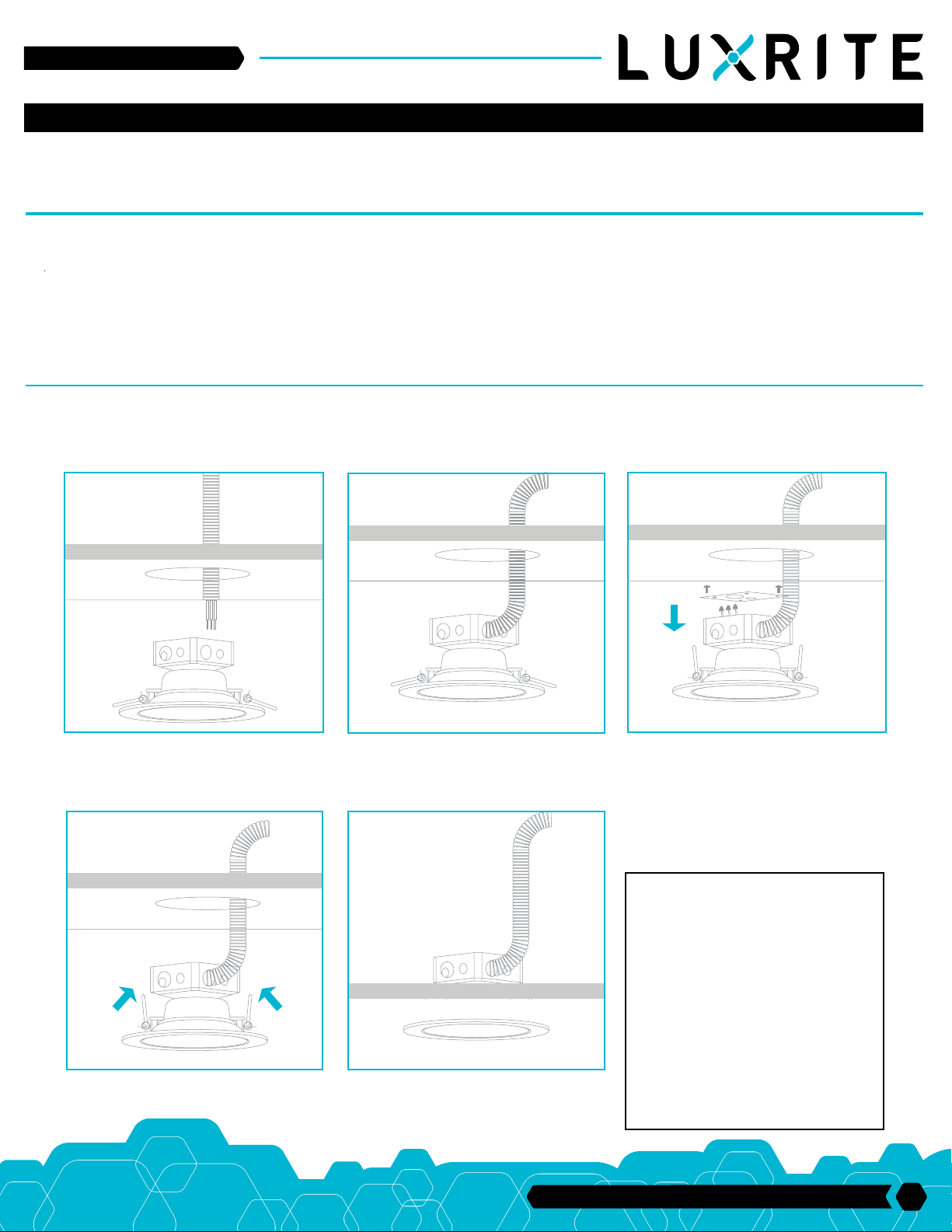
FIG. 1 FIG. 2 FIG. 3
Cut 4.72in hole in the ceiling. A template is provided to
assist with laying out the hole location (FIG. 1)
When running the supply wire(s), allow an additional
18in of wire at each installation in order to make the
electrical connections on the room side of the ceiling
hole (FIG. 2)
FIG. 4 FIG. 5
Press the top portion of the Remodel Clips against the
side of the Housing Assembly (FIG. 4)
Push the Housing Assembly with the top side of the
Remodel Clips through the hole until tight. Continue to
push the Housing Assembly until the fixture snaps into
place with the trim tight against the ceiling (FIG. 5)
Remove the Junction Box Screws holding the
Junction Box Cover. Pass the supply wire(s) through
the appropriate knockout hole on the Junction Box.
Make the electrical connections to fit inside
Junction Box following the ELECTRICAL CONNECTIONS. Make sure all connections are secure, tuck
all wires inside Junction Box and reinstall Junction
Box Cover using the Junction Box Screws (FIG. 3)
DIMMING
Dimming performance may depend on the
dimmer, the dimmer range adjustment setting
(for dimmers with brightness range adjustments),
the wiring method, and/or the number of LED
modules installed onto the dimmer circuit. For
dimmer selection, Dimming control manufacturers
revise their product often; for the latest list of
compatible dimmers please visit our website.
For best restults, it is recommended to install a
minimum of four LED modules onto one dimmer.
Before turning on the LED lights, set dimmer
position at maximum before adjusting to a lower
light level. Please follow the dimming control
manufacturer’s instructions for the installation of
all dimming controls.
33 Randolph Ave. • Avenel NJ 07001 | 732-882-1500
1
 Loading...