

Page 1
www.allstarlighting.com
INSTALLATION GUIDE
DOB LED WALLPACK
LR40500, LR40510, LR40520
IMPORTANT SAFEGUARDS
When using electrical equipment, basic safety precautions should always be
followed including the following:
READ AND FOLLOW ALL SAFETY INSTRUCTIONS
1. To reduce the risk of electrical shock, turn off power supply before installation or servicing,
2. This luminaire must be installed in accordance with the NEC or your local electrial code.
If you are not familiar with these codes and requirements, consult a qualified electrician.
3. If NEMA photo control is installed refer to NEMA Receptacle section for instructions,
4. Verify the availability of necessary tools and incidental material.
TO INSTALL
1
Screws
Connector
2
Rear Cover
J-box fasteners
Rear Cover
Auxiliary Mounting Holes
4” Recessed J-box
UP
Supply Wire
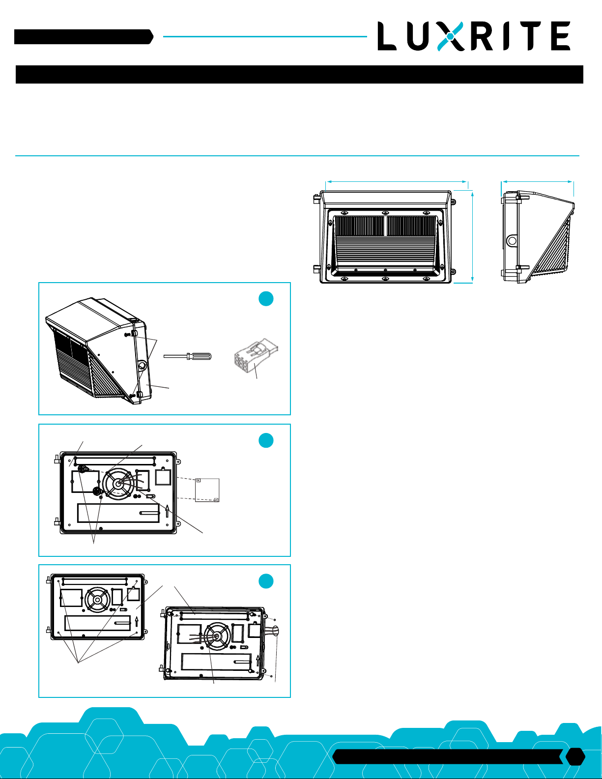
7.4” (186mm)14.2” (360mm)
9.2” (235mm)
LUMINAIRE INSTALLATION
STEP 1 (Figure 1)
Remove two screws, remove the rear cover of the luminaire and pull the connector.
STEP 2-1 (Onto a recessed 4” rectangular/octagonal J-Box)
(Figure 2)
1. Verify that supply power is off and that the J-Box is securely mounted within the
structural surface.
2. Remove both J-Box fasteners from J-Box (set aside for re-installation as needed).
3. Drill holes as J-Box required on the rear cover.
4. Position Rear cover over J-Box feeding supply wires thru the center of the rear
cover and slit in gasket. Replace fasteners from Step 2 (do not fully tighten).
5. Using a contractor level, ensure Rear cover is level and fully tighten fasteners (use
washers as required to ensure a secure fit).
Auxillary
Mounting Holes
UP
Rear Cover
Supply Wire
UP
Conduit
3
STEP 2-2 (Conduit-stub up) (Figure 3)
1. Drill holes on the rear cover as auxiliary mounting holes.
2. Verify that supply power is off. Using a contractor level, ensure rear cover is level
and mark mounting surface thru selected auxiliary mounting holes.
3. Drill holes as marked in Step 1 and install appropriate mounting inserts capable of
handling fixture load requirements.
4. Feed supply wires thru the center of the rear cover and slit in gasket.
5. Ensure rear cover is level. Fully tighten fasteners (use washers as required to
ensure a secure fit).
33 Randolph Ave. • Avenel NJ 07001 | 732-882-1500
1
Page 2
www.allstarlighting.com
INSTALLATION GUIDE
Auxillary
Mounting Holes
COMMON
GROUND
Housing Indicators
LINE
DIM+
DIM-
Conduit
Rear Cover
BLACK
WHITE
GREEN
PURPLE
GRAY
Supply Wire
Rear Cover
4
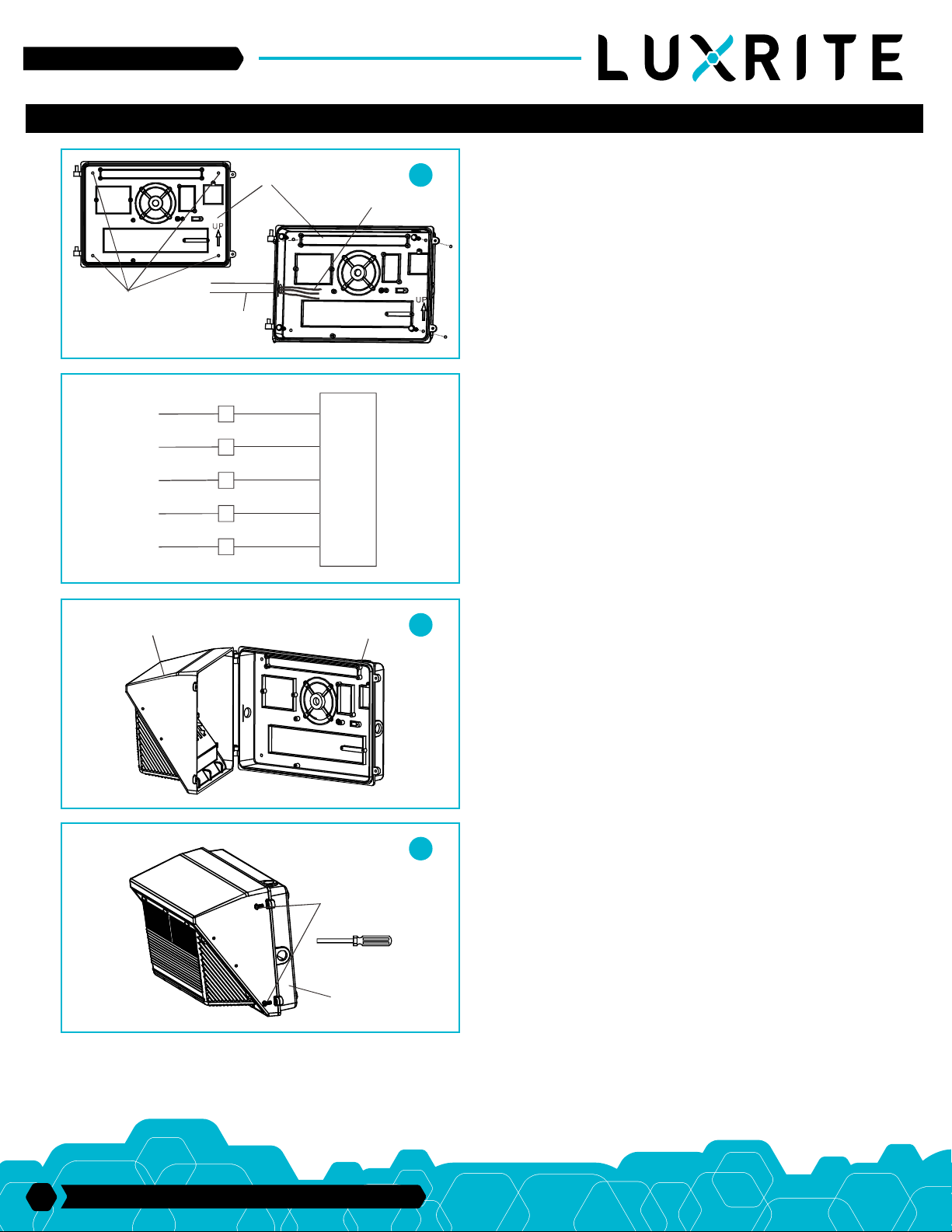
STEP 2-3 (Conduit-surface) (Figure 4)
1. Drill holes on the rear cover as auxiliary mounting holes.
2. Verify that supply power is off. Using a contractor level, ensure rear cover is level
and mark mounting surface thru selected ausiliary mounting holes.
3. Drill holes as marked in Step 1 and install appropriate mounting inserts capable of
handling fixture load requirements.
4. Ensure rear cover is level. Fully tighten fasteners (use washers as required to
ensure a secure fit).
5. Attach 1/2” NPT conduit fittings using the appropriate EMT rain tight compression
connections (not provided) onto the factory machined conduit entry opening.
STEP 3
Make supply wire (power and dimming) to fixture wire connections as required thru
splice access. Universal voltage driver permits operation at 120V thru 277V, 50 or
60Hz 0-10V control wires must be rated for 300V minimum. For 0-10V Dimming,
follow the wiring directions as shown on the figure to the left.
5
STEP 4 (Figure 5)
Fixture slightly upward, align fixture housing indicators with rear cover hooks and
slip fixture back onto hooks and insert the connector.
6
Screws
Rear Cover
TROUBLESHOOTING
If this fixture fails to operate properly, check to make sure: The fixture is wired correctly. The fixture is grounded correctly. The line voltage at the fixture is correct. If all these
variables have been checked and the fixture still does not operate as specified, contact your local distributor.
STEP 5 (Figure 6)
Close the housing indicators to the rear cover and fully tighten fasteners.
2
33 Randolph Ave. • Avenel NJ 07001 | 732-882-1500
 Loading...