

Page 1

P 5 2 1 U c
SM ART TEM P®UN IV ERSAL 5/2-D AY
PR OG RAMMABLE OR N ON -P RO GRAMMABLE T HE RM OS TAT
(F OR BOTH CON VE NTI ON AL AND H EAT PUM P SYSTE MS )
I N S T A L L AT I O N A N D O P E RAT IN G I N S T R U C T I O N S
52175
IMPORTANT!
• Ple ase read all of these in struc tions ca refully before b eginning
insta llati on.
• Lab el every wire termina l des ignation on y our exis ting the rmostat wirin g
befor e removi ng your old ther mosta t.
• Ign ore the color of the wir es si nce they may not comply with any
stand ard. Please c onnect w ires usi ng th e t ermin al lette r design ation s.
Th ank you f or your con fi dence in ou r product . To o bt ai n the b es t results f ro m
yo ur invest me nt, p lease r ea d and fol lo w th e insta ll at io n proce du re s caref ul ly, an d
on e step at a t ime. Th is will s av e yo u time an d minimiz e th e chanc e of damaging
ei ther the th ermostat or p ossibly y ou r heating a nd coolin g sy stem. T he se
in struction s may conta in informat io n beyond th at w hich ma y be requir ed f or your
pa rticular in stallatio n.
CAU TIONS AND WARNIN GS . . . . . . . . . . 2
SYS TEM C OMPATIBILITY . . . . . . . . . . . . 3
FEATURES . . . . . . . . . . . . . . . . . . . . . . . 4
TOOLS YO U MAY NEE D . . . . . . . . . . . . . . 4
MOUNT ING LOCATION . . . . . . . . . . . . . . 5
REMOV E OLD TH ERMOSTAT . . . . . . . . . . 5
INSTALL T HERMO STAT BASE . . . . . . . . . 6
WIRIN G INFORM ATION . . . . . . . . . . . . . . 7
WIRIN G DIAGRA MS . . . . . . . . . . . . . . . . 9
COMPL ETE THE INSTALL . . . . . . . . . . . 18
FRONT PAN EL IT EMS . . . . . . . . . . . . . . 18
SYS TEM C ONFIGURAT ION AND SETUP
OPTIO NS . . . . . . . . . . . . . . . . . . . . . . . 20
OPERATING INST RUCTIONS . . . . . . . . . 23
TEMPE RATU RE PR OGRAMS . . . . . . . . . 25
ADVANC ED FE ATUR ES . . . . . . . . . . . . . 26
BATTERY REPL ACEME NT . . . . . . . . . . . 30
TECHN ICA L ASSISTA NCE . . . . . . . . . . . 31
LIMIT ED WARRANTY . . . . . . . . . . . . . . 3 1
MERCU RY NOTICE . . . . . . . . . . . . . . . . 32
WARN ING: Use E nerg izer®or DURAC ELL® Alkaline Bat teries Only.
Ener gizer®is a regist ered t radem ark of Eveready Batt ery Co mpany, I nc.
®
DURA CELL
© 201 4 LUX P ROD UC TS CO RPO RAT ION . A LL RI GH TS RE SER VE D
is a regist ered t radem ark of The P rocter & Ga mble Company
Page 2

CAU TIONS AND WARNIN GS:
• This th er mostat re qu ires batter ie s to oper at e and failu re or sub-s ta ndard
pe rformance o f the bat te ri es may im pa ir or p re ve nt the co rr ect ope ra ti on of
th e thermos ta t. Us e Duracel l®or Energize r®al kaline ba tt er ies ONLY for al l
LU XPRO ther mo stats req ui ri ng batter ie s. BE S URE T O CHANG E THE B ATT ERIES
AT LEAST ONC E A YEAR, or wh en ever you se e the LO BAT T indicatio n on the
sc reen. Fail ur e to foll ow t hese batt er y in struction s could res ul t in prop er ty
da ma ge and/ or p ersonal i nj ur y.
• The e le ct rical r at in g for thi s thermosta t is 1.5 Amps per te rminal, with a
ma ximum tot al load of 3. 0A for al l terminals c ombined.
• The t he rm ostat con ta ins parts t ha t may wea r out throu gh use and ar e
su sceptible t o failure i f over-loade d or used i n a manner ot he r than as
in dicated i n th e docum en ta ti on.
• Ch ec k unocc up ie d resid en ce s regul ar ly to ens ur e that all sy st ems are
op erating p ro pe rly.
• Ch ec k any hea ti ng /air- condition in g system in cludi ng t his pro du ct before
op eration a nd a t regular i nt er vals.
• El ec trical in te rferenc e, st at ic electric it y, f ai lu re or s ub st andard pe rf ormance o f
ba tt eries, wirin g de fects i n th e insta ll at io n and/o r ch aracter is ti cs of t he
co nnected H VAC d ev ices ma y pr event t he s ystem f ro m regulatin g he at ing and
co oling as an ticipated .
• The t he rm ostat is a sensitive d evice and d ropping t he product ca n cause
da ma ge to c ri ti cal com po ne nts. If the pr od uct is dr op ped or sh ak en viol en tl y
du ring tran sp ort or in st allation th en it sho ul d be repl ac ed immedi at el y.
• Persons w it h physica l or mental l imitations ma y not be ab le to pro mp tly
re spond to a malfuncti on of the h ea ti ng/air-condi ti on ing sys te m.
• All r es id ents sh ou ld be mad e aw are of th e potential i n any syste m for
ma lfunction s that coul d ca use con ti nu ous hea ti ng o r cooli ng a nd shou ld b e
fa miliar wi th the oper at io n and l oc at io n of th e he at ing/coo li ng applianc e on/off
sw it ch.
• Re ad the in st ru ction m an ua l compl et el y befor e in stallin g th e therm os ta t. You
sh ould cons ul t a quali fi ed HVAC tech ni ci an or a n el ectrici an i f you d o no t fully
un derstand th e install at io n instr uc ti ons.
2
Page 3
HOLD
S
ET
RUN
D
AY/T IME
TEM P P ROG
AIR FI LTER
T
EMP ERAT URE
H
EAT
OFF
COO L
F
AN
A
UTO
O
N
EME R
NEX T
P 5 21 U c
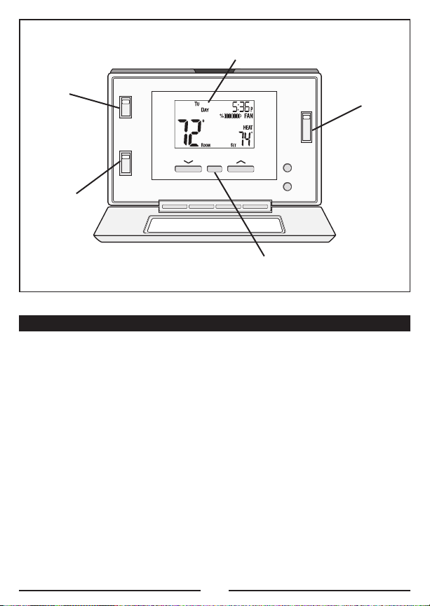
LCD Display Screen
Fan Mode
Switch
Set Slide
Switch
System Mode
Switch
UP, DOWN and HOLD Buttons
SYS TEM C OMPATIBILITY:
Th e electri ca l rating fo r this th er mo stat is 1 .5 Am ps p er term in al , w it h a
ma ximum tot al combined l oad of 3. 0A for all te rminals c om bined.
CO MPAT IBLE WI TH :
• Mo st 24-vol t he at ing and c oo ling sy st em s
• 1 or 2 stage He at / 1 stage Co ol: G as, O il or Ele ct ric syste ms
• 1 or 2 stage He at / 1 stage Co ol: H ea t Pump sy st ems
• 3- wi re hydr on ic (hot w at er ) zone va lv es
• Ga s Millivo lt h ea ters
NOT COM PATI BL E WITH:
• 12 0/ 240 VA C li ne-volt ag e systems ( wi thout a t ra nsformer) , ask y our LUXPR O
de aler for th ermostats t o control t he se syst em s.
3
Page 4

FEATURES:
• 1 or 2-Heat / 1 -C ool, 5/2-day p rogrammin g
• Un iv ersal C om pa ti bility fo r all sys te m types
• Weekdays an d W eekends c an be pro gr am med sep ar at ely
• Ex clusive L UX®Sp eed SlideTMfo r easy pr og ramming
• Us er- se le ctable pe ri ods per d ay (2 or 4)
• Us er- se le ctable pr og rammabl e or non-pr og ra mmable op er ation
• Lu xL ight®EL (Electro -L uminescen t) lighted di splay
• Pr og rammabl e ai r filte r li fe time r
• Ke yp ad lock ou t for una ut ho rized u se rs
• Ma nu al temp er at ur e hold
• Tem porary temp er at ure ove rr id e
• Ad ju stable te mp erature d if fe rential / cycl e-rate
• Ad ju stable 2n d heat stage Of fset sett in g
• Us er temper at ur e calibra ti on
• Ad ju stable he at /c ool set t em perature li mit stops
• Sm ar t recov er y
• Du al -powered (b at tery and/or 2 4- volt sy st em powered)
• Ba tt er y- free memo ry s to rage
• F/ C tempera tu re d isplay
• 12 /2 4-hour clock dis pl ay
• 5/ 2- minute se le ctable ti me delay fo r equipme nt p rotecti on
TOOLS YO U MAY NEE D:
• Sc re wdriver s
• Wi re Stripp er
• Wi re Cutter
• Dr il l with as so rted dr il l bits (n ew i nstalla ti on s only)
4
Page 5
MOUNT ING LOCATION :
OF
F
On replacem en t install at io ns, m ount th e ne w therm os ta t in plac e of the ol d on e
un less the co nditions li sted belo w su ggest o th er wise. On ne w in stallatio ns ,
pl ease foll ow t hese ge ne ra l guide li ne s:
1. Mount th e thermos ta t on an ins id e wall, about 5 ft. ( 1.5m) abo ve the floo r.
2. Do not l oc ate the t he rmostat whe re air circ ul at ion is po or such as in a corner,
al cove, or beh in d a door th at i s norma ll y left op en .
3. Do not l oc ate the t he rmostat whe re unusual he at ing or co ol ing condi ti ons may
be present, su ch a s: di rect su nl ig ht, a bove a la mp , t el evision , or ra di ator, or on
a wall next t o an exte ri or door o r window.
4. Do not l oc ate in a da mp enviro nm ent, as this c an lead to co rrosion t ha t may
sh orten the rm ostat lif e.
5. If pai nt in g or co ns tr uction wo rk is sti ll o ngoing, cove r th e therm os ta t
co mpletely or wait unt il this wor k is comple te before i ns tallation .
WARNING :
Al l wiring mu st confor m to the lo ca l codes a nd ordinanc es that are i n your
pa rticular lo ca tion.
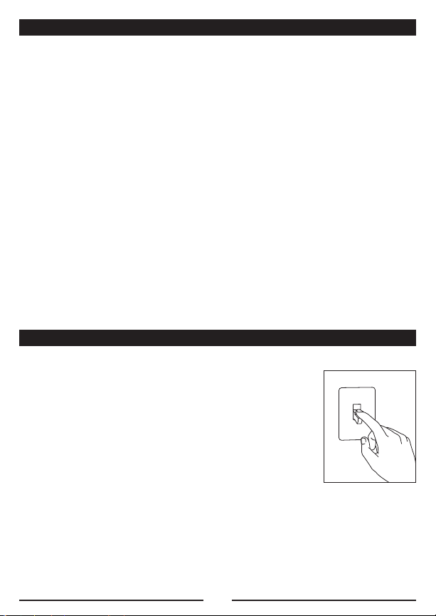
REMOV E OLD TH ERMOSTAT:
1. Turn OFF t he electric it y to all he at ing and c oo ling
co mponents. Do n ot turn t he e lectric it y back on u nt il
al l work is c ompleted.
2. Remove t he front po rt ion of yo ur old th er mo stat to
ex pose the wi ring conn ec tions.
3. Wr it e down th e letters p ri nted near e ach wire te rminal
th at is use d, an d al so the co lo r of ea ch w ire tha t is
co nnected t o it. Self-ad he si ve wire l ab els are a ls o
en close d.
4. Carefu ll y remove th e wires o ne a t a time, and be nd them i n a manner so that
th ey do not f all back in side the wa ll. D o not a ll ow b are wir e en ds to t ou ch
ea ch other.
5. Loosen t he mounti ng s crews f or t he old th er mostat an d carefully r emove it
fr om the wa ll .
5
Page 6

INSTALL T HERMO STAT BASE:
THERM OSTAT TOP VIE W
1. Strip wi re insula ti on leaving on ly 3/8 in. (9.5m m) bare wir e ends, and cl ean off
an y corrosi on p resent.
2. Fill t he wall o pe ning with n on-combus ti ble insul at io n to prev en t drafts fr om
af fecting t he thermost at ’s normal op er at ion.
3. Separa te n ew thermo st at housing us ing your th umb and i nd ex finger. P ro vide
pr essure in o pposite d ir ections t o the relea se tabs on th e top of th e housing ,
in the dire ct ions show n in the di ag ra m shown abo ve .
4. Route th e wires t hr ou gh the op en ing in th e new the rm os tat base pl at e, an d
ho ld the ba se a gainst th e wall. Tr y to line u p the screw h oles from t he prior
th ermostat, and in st all the m ou nting s cr ew s.
5. If the p re vious h ol es cannot b e used, hold t he t hermost at b ase against t he
wa ll so tha t it a ppears st ra ight an d le vel (po si ti on the ba se for be st
ap pe arance) a nd mark f or t he new sc re w holes . Attach th e base to t he wall
us ing the s cr ews provi de d (use th e supplied pl astic anc ho rs if nee de d when
mo unting to a soft mat er ia l such as d ry wall).
6
Page 7

WIRIN G INFORM ATION:
CO NNECTING TH E WIRES:
Wh en attach in g the wir es t o the t he rm ostat, please en su re that t he bare wir e
en ds are he ld AL L the way i nt o the t er mi nal blo ck w hile th e sc rew is be in g
ti ghtened.
WI RING BASE P LATE NOT ICE:
Th is thermo st at model is p art of a fa mily of s im ilar mo de ls that have th e same
ge neral vis ua l appeara nc e. E ve n thoug h th is base p la te may lo ok t he same a s
ba se plates f ro m other m od els, the wir in g connect io ns may ha ve d if ferent
te rminal le tt ers for d if ferent pu rp oses. Pleas e do not in te rc hange t he b ack pla te s
an d/or ther mo stat fron t ha lves of o th er simi la r looking m od els. Doing so m ay
ca use undes ir ed heatin g an d/or co ol in g opera ti on t o occur.
7
Page 8

WI RING DIAG RA M NOT ES :
(I mportant, pl ea se read a ll n otes be fo re connec ti ng wires)
• If t he info rm at io n provi de d in the fo ll owing wir in g diagrams do es not cl early
re present o r ma tch you r sy stem, please r ef er to t he “T EC HN ICAL ASSISTANCE ”
se ction of th is manual , a nd c ontact us b efore r em ov ing any o f yo ur exis ti ng
th ermostat wi ri ng.
• All o f th e dashe d wi res sho wn i n the wir in g diagrams ar e either op tional, or
th eir usage d ep ends up on y our spe ci fi c syste m ty pe or b ra nd . For exa mp le:
Di ag ram #1 sh ow s the fan w ir e as op ti on al. If your s ys tem doe s no t have a
fa n, th an this t er minal w il l not be us ed .
• Term in al letter s shown in bl ac k represe nt typical wi ring applic at io ns.
De pending u po n the bra nd of your sp ecific sy st em or the rm ostat, your te rm in al
le tters may n ot match ex ac tly. Term inal le tt er s shown i n gr ay repr es en t other
po ssible wi ri ng design at io ns that y ou m ight se e on your e xi st ing the rm os ta t
te rminals.
• The o pt io nal “ C” terminal is used for p ow ering the t hermostat b y the 24-vo lt
sy stem, using th e System Co mm on wire . This ca n be used a lo ne , o r in
ad dition to i nstalling b at teries as a backup . NO TE : c on ne cting t he S ystem
Co mmon wire t o the the rm ostat is no t necessa ry f or heating an d cooling t o
fu nction pr op erly.
• If y our old t he rmostat h as b oth a “Y” and “C” wire both p resent, then “C” is
mo st likely a System C om mon wire.
• For Heat Pu mp system s, yo u wi ll use ei th er the “O” termin al o r the “B”
te rminal on t his therm os ta t, bu t not b ot h. I f your ol d th ermosta t ha s both an
“O ” a nd a “B ” w ir e prese nt , t he n “ B” is l ik ely a S ys te m Commo n wi re and ma y
be connecte d to the “C” termin al . Co nn ecting a Sy stem Co mm on wire t o th is
th ermostat’s “B” termina l may damag e th e therm os ta t, an d also yo ur h ea ting
an d cooling s ystem.
• So me Heat Pum p sy stems h av e a wire fo r AUX e lectric h ea t (usually W2), and
al so a sepa ra te wire f or E mergenc y electri c heat (usual ly E). Th is thermo st at
us es the W2 te rm in al for bo th AU X and Eme rg en cy He at . Tape o ff y our “E”
wi re, a nd conf ir m that all co mp onents fu nc tion wi th ou t it.
• If r eplacin g an old th er mo stat that h as a mechan ic al cl oc k, th er e may b e tw o
wi res label ed as “ C” fo r the c lock power. Tape o ff these wi re s and do no t
co nnect the m to the “C” termin al o f this th er mostat.
8
Page 9

WIRIN G DIAGRA MS:
DIAGR AM SYS TEM T YPE / DE SCRIPTIO N PAGE #
#1 CO NVENTIONA L: HE ATING ..........................................................10
1- STAGE OR 2 -S TAG E
2, 3, 4, 5 WI RE S
#2 CO NVENTIONA L: HE ATING ..........................................................11
3- WIRE ZONE VA LVE
3, 4 WI RES
#3 CO NVENTIONA L: CO OLING ..........................................................12
1- STAGE
3, 4 WI RES
#4 CO NVENTIONA L: HE ATING AND CO OLING .....................................13
1- STAGE HEAT
4, 5 WI RES
#5 CO NVENTIONA L: HE ATING AND CO OLING .....................................14
2- STAGE HEAT
5, 6 WI RES
#6 CO NVENTIONA L: HE ATING AND CO OLING .....................................15
TW O-TRANSFO RM ERS
5, 6 WI RES
#7 HE AT PUMP: HE ATING AND CO OLING .....................................16
SI NGLE-STAGE O NLY
4, 5 WI RES
#8 HE AT PUMP: HE ATING AND CO OLING .....................................17
WI TH AUX / EM ERGENCY H EAT
5, 6 WI RES
9
Page 10
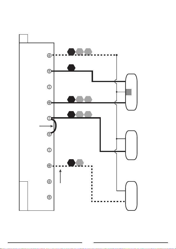
NOTE: THE BLACK TERMINAL LETTERS ARE TYPICAL, GRAY TERMINAL LETTERS ARE BRAND SPECIFIC
W1
4
W
XF
G
B*
W2
RH
V
R
W1 A W2O B CG Y RC RH
1-STAGE OR 2-STAGE, HEATING ONLY
(INCLUDING MILLIVOLT)
(2-WIRE HEAT USE “RH” & “W1”)
Factory RH-RC Jumper Wire Installed
#12, 3, 4, 5 WIRES
C
HEATE R
STAGE
1
STAGE
2
FAN
SYS TEM 24V
TRA NSFO RMER
SYSTEM COMMON
FAN WIRE
MAY NOT BE
PRESENT IN
ALL SYSTEMS
O
P
T
I
O
N
A
L
10
Page 11

NOTE: THE BLACK TERMINAL LETTERS ARE TYPICAL, GRAY TERMINAL LETTERS ARE BRAND SPECIFIC
X
B*
C
RH
V
R
W1
4
W A
W1 A W2O B CG Y RC RH
HOT WATER HEATING ONLY
(WITH A 3-WIRE ZONE VALVE)
Factory RH-RC Jumper Wire Installed
#23, 4 WIRES
SYS TEM 24V
TRA NSFO RMER
SYSTEM COMMON
OPEN = Heat On
CLOSE = Heat Off
3-W IRE ZONE VALVE
OPE N CLOS E
O
P
T
I
O
N
A
L
11
Page 12

NOTE: THE BLACK TERMINAL LETTERS ARE TYPICAL, GRAY TERMINAL LETTERS ARE BRAND SPECIFIC
XF
G
Y1
6
Y
B*
RC
V
R
W1 A W2O B CG Y RC RH
1-STAGE, COOLING ONLY
Factory RH-RC Jumper Wire Installed
#3
C
FAN
SYS TEM 24V
TRA NSFO RMER
SYSTEM COMMON
3, 4 WIRES
O
P
T
I
O
N
A
L
AIR
CON DITIO NER
12
Page 13

NOTE: THE BLACK TERMINAL LETTERS ARE TYPICAL, GRAY TERMINAL LETTERS ARE BRAND SPECIFIC
RH
RC
V
R
Y1
6
Y
F
G
XW1
4
W
B*
W1 A W2 CGO B Y RC RH
CONVENTIONAL (NON HEAT PUMP)
1-STAGE HEATING AND 1-STAGE COOLING
Factory RH-RC Jumper Wire Installed
#4
C
FAN
SYS TEM 24V
TRA NSFO RMER
SYSTEM COMMON
HEATE R
AIR
CON DITIO NER
4, 5 WIRES
O
P
T
I
O
N
A
L
13
Page 14

NOTE: THE BLACK TERMINAL LETTERS ARE TYPICAL, GRAY TERMINAL LETTERS ARE BRAND SPECIFIC
W2
RH
RC
V
R
Y1
6
Y
F
G
XW1
4
W
B*
W1 A W2 CGO B Y RC RH
CONVENTIONAL (NON HEAT PUMP)
2-STAGE HEATING AND 1-STAGE COOLING
Factory RH-RC Jumper Wire Installed
#5
C
FAN
SYS TEM 24V
TRA NSFO RMER
SYSTEM COMMON
AIR
CON DITIO NER
5, 6 WIRES
O
P
T
I
O
N
A
L
HEATE R
STAGE
1
STAGE
2
14
Page 15

NOTE: THE BLACK TERMINAL LETTERS ARE TYPICAL, GRAY TERMINAL LETTERS ARE BRAND SPECIFIC
X
B*
C
R
V
RH
R
V
RC
Y1
6
Y
F
G
W1
4
W
W1 A W2O B CG Y RC RH
CONVENTIONAL (NON HEAT PUMP) 1-STAGE HEATING AND
1-STAGE COOLING WITH TWO SEPARATE 24V TRANSFORMERS
Factory RH-RC Jumper Wire REMOVED
#6
FAN
HEAT 24V
TRA NSFO RMER
COO L 24V
TRA NSFO RMER
SYSTEM COMMON
HEATE R
AIR
CON DITIO NER
5, 6 WIRES
O
P
T
I
O
N
A
L
15
Page 16

NOTE: THE BLACK TERMINAL LETTERS ARE TYPICAL, GRAY TERMINAL LETTERS ARE BRAND SPECIFIC
O
XF
G
Y1
6
Y
B*
RC
V
R
W1 A W2O B CG Y RC RH
SINGLE-STAGE HEAT PUMP SYSTEM
WITH NO AUX OR EMERGENCY HEAT
#7
C
FAN
SYS TEM 24V
TRA NSFO RMER
SYSTEM COMMON
4, 5 WIRES
O
P
T
I
O
N
A
L
HEAT PUMP
REV ERSI NG
VALVE
** Use “O” or “B”
Terminals, Never Both
CUSTOMER INSTALLED Y-W1 Jumper Wire
Factory RH-RC Jumper Wire Installed
16
Page 17

NOTE: THE BLACK TERMINAL LETTERS ARE TYPICAL, GRAY TERMINAL LETTERS ARE BRAND SPECIFIC
CUSTOMER INSTALLED Y-W1 Jumper Wire
X
B*
C
W3
W
W2
O
F
G
Y1
6
Y
RC
V
R
W1 A W2O B CG Y RC RH
2-HEAT / 1-COOL, HEAT PUMP SYSTEM
WITH AUX AND EMERGENCY HEAT
Factory RH-RC Jumper Wire Installed
#8
FAN
SYS TEM 24V
TRA NSFO RMER
SYSTEM COMMON
5, 6 WIRES
HEAT PUMP
REV ERSI NG
VALVE
** Use “O” or “B”
Terminals, Never Both
AUX / EM ERG.
HEAT
O
P
T
I
O
N
A
L
17
Page 18

COMPL ETE THE INSTALL:
GA S
EL EC
BATT ERY
IN STALL BATTE RI ES INTO T HE RM OSTAT: I ns tall tw o br and new E ne rgizer®or
DU RACELL®“A A” s iz e alkalin e (only) ba tt er ies, into the th ermostat’s b at te ry
co mpartment . En su re the ba tt er ies are i ns talled in t he prop er d irectio n.
GA S / ELEC CI RCUIT BOARD OPTI ON (“G” TERMIN AL FA N OP ERATION): T hi s
se tting is a plastic s ho rting cap c al led a j um pe r. T hi s jumper mu st remain
in stalled, and s et to eit he r GAS or EL EC TRIC fo r yo ur syst em t o work pr op erly.
Th is settin g changes h ow y our sys te m’s blower fan ( if applic ab le ) is co nt ro lled
wh ile the t he rmostat i s in HEAT or E ME RG HEAT mo de , w he n the Fan s witch i n
th e A UT O posit io n. This s et ting do es n ot affe ct t he fan op er at ion whi le i n COOL
mo de.
Wh en set to “G AS ”, th e blower fa n is contro ll ed solely b y the hea ti ng system
it self. Syste ms t ha t would t yp ically us e the “ GAS” setting w ou ld be: natural g as,
pr opane, or oi l fu rnaces, and bo il ers. NOTE: If yo ur b lo wer fan d oe s not o pe ra te
pr operly af te r install at io n, mo ve the Ga s / Elect ri c option to t he “E lectric ” set ti ng .
Wh en set to “E LE C” , t he
bl ow er fan is c ontroll ed
di rectly by t he thermo st at .
Th is settin g is requir ed for
he at ing sys te ms that do no t
co ntrol the ir o wn fan, such a s
HE AT PUMPS, and u ni ts that
on ly have a n el ectric- re si stive
he at ing ele me nt as the h ea t
so urce.
FRONT PAN EL IT EMS:
Th ese items b elow are al l located b eh in d the d oo r on the fr on t of th e th ermosta t.
To open th e door, pull ou tw ards us in g the sma ll i ndentatio n in the ce nt er of the
to p edge of t he thermo st at housin g.
HE AT / OFF / C OOL, SYSTE M MO DE SWIT CH : Se t this sw it ch to HEAT t o control
yo ur heatin g sy stem, and CO OL t o contr ol y our coo li ng system . The OFF p os ition
wi ll disabl e both the he at ing and c oo ling un it s.
18
Page 19

AU TO / ON, FAN MODE S WI TCH: Wh en this s wi tch is in AUTO , the b lo wer fan ( if
pr esent in yo ur system ) will auto ma ti cally c ycle on a nd off by i tself w hi le heating
or cooling is running. When i n th e ON po si ti on, t he blower f an will r un c onstant ly
wi th or wit ho ut a dema nd for heat in g or cool in g, ev en when t he S ystem M od e
sw it ch is i n th e OFF p os it ion.
NO TE: Th e Fan Mod e sw itch only w orks if y ou r system pr ovides a wi re for th e
th ermostat’s “G” wire te rm inal, to contr ol a blower f an . The Fan Mode s wi tch
ha s no effe ct in syste ms that do no t ha ve a bl ow er f an (suc h as a hot wa te r
ra diator sy st em ).
MU LTI-FU NC TI ON, S ET SLID E SW ITCH: This s wi tc h provide s an easy w ay to
qu ickly acc es s the mos t commonly us ed thermo st at settin gs . This sw it ch has 4
in dividual po sitions, and u nl ess a s pe ci fic set ti ng is bei ng a djusted , thi s sw it ch
sh ould alwa ys r emain i n th e RU N posit io n for the t he rmostat t o control t he room
te mperature . The oth er S et Slid e sw it ch posi ti on s are d es cr ibed in g re ater deta il
in the ADVAN CED FEATUR ES section. NOT E: th is s witch i s on ly oper ab le when t he
th ermostat is i n “ Pr ogramma bl e” mo de . Whe n th e therm os ta t is used i n
“M anual” contr ol m ode, all 4 o f th e switch po si tions w il l act lik e th e RUN
po sition, exce pt t he “A IR FILTER” positio n.
UP / DOWN B UT TONS: The UP a nd DOWN b ut to ns are us ed to adj us t an y item
th at can be c ha nged by t he user. Exa mp le s are t he s et temp er at ures, cloc k
ti mes, and day s of the we ek . In m an y cases , an it em may be f la shing i f it can
cu rrently b e adjusted.
HO LD BUTTON : T hi s button ac ti va tes and d ea ctivates th e manual Temp er at ure
Ho ld featur e.
EM ER BUTTON : W he n in Norm al R un mode , the u sa ge of thi s bu tton va ri es
de pending u po n your sp ec ific syst em configur at io n. For he at p ump sys te ms ,
pr essing th is button e na bles your e mergency heat func ti on, w hich is d es cribed in
gr ea ter det ai l in the OP ER ATING INST RU CT IO NS sect io n. For conve nt ional
sy stems, there i s no such t hi ng as e me rg ency he at , s o this butt on will hav e no
ef fect.
NE XT BUTTON : T hi s button is m ostly u se d while s et ti ng item s su ch as s of tw are
op tions, and t em pe ra ture pr og ra m perio ds . When th er e are s ev er al item s on the
sc reen that c an be cha ng ed , u su ally on e of them i s fl ashing in di ca ting th at i t can
be adjusted . Pr es sing th e NE XT butt on w ill cycle th ro ug h which i te m is fl as hi ng.
19
Page 20

SYS TEM C ONFIGURAT ION AND SETUP OP TIONS:
Se tup optio ns for how th e thermos ta t wi ll func ti on , a lo ng with c ho osing y ou r
pa rticular sy stem type , a re p erforme d us ing a m en u on the di sp lay scr ee n.
TO ACCESS T HE SETUP ME NU : Move th e Sy stem Mo de s wi tch int o th e OFF
po sition, and th en hold d ow n th e EMER bu tt on for ap pr ox imately 5 s econds un ti l
th e screen ch anges. Th e menu wi ll always s ta rt with i te m #1, a nd is a dv an ced to
ea ch follow in g item by a s ingle p re ss of the N EX T butto n. The op ti on s for e ac h
it em are ch an ged using t he UP or DO WN button s.
IT EM #01 (C LK = CLOCK FO RMAT): [ 12Hr, default ] Thi s displays th e clo ck times
us ing stand ar d A M and PM va lu es. [24Hr] This di sp lays th e clock t im es using th e
mi litary-time f or mat (exam pl e 22:00 h ou rs, w ithout us in g A M or PM).
IT EM #02 (T MP = TEMPER ATU RE SCAL E) : [ F, defaul t] S hows all te mperature
va lues in Fahrenhe it . [C ] Shows all t emperatur e va lues Ce ls iu s.
IT EM #03 (T HE RMOSTAT TYP E) : [P ROG, default ] Us e this se tt ing for f ol lowing a
da ily progr am routine. [ MA N] Th is settin g om its the p ro gram ro ut in e and
op erates as a m anual s ty le non-pr og ra mmable th er mostat. T hi s is ve ry b as ic and
on ly shows th e room te mp er at ure and s et temper at ur e on the sc re en, with no
clock.
IT EM #04 (P ER D = PERIO D QUANTITY) : [4 P, de fault] Thermos ta t uses fo ur
pe riods per d ay (calle d MORN, DAY, EV E, an d NITE). [2P] The th er mostat us es t wo
pe riods per d ay (calle d DAY and NI TE ).
IT EM #05 (R CV = EARLY RECOVE RY): [OFF, default ] Program S et Tem perature
va lues star t to occur at e xactly th e period st ar t times . [O N] E arly Re co ve ry
af fects how t he transi ti on occurs w he n chang in g from th e NI TE to t he M ORN
pe riod, and wh en c hanging f ro m the D AY to the EVE pe riod. T he thermost at
ca lculates ho w lo ng it t ak es for yo ur h ome to re co ver fro m a setback o n a daily
ba sis, and tur ns o n ahead o f time in o rd er to r ea ch the ta rg et set po in t of the
ne xt upcomi ng program pe riod by t he period’s st art time. While in a recovery,
th e word “RECO V.” will be s ho wn on the d is play scre en .
IT EM #06 (S YSTEM M OD E) : [ FU RN , d efault] This i s for the m aj ority of he at ing
sy stems tha t ar e not H ea t Pu mps, such as a g as furn ac e or hot wa te r boiler. [H P]
Us e this se tt ing if yo u ha ve a He at P um p syste m, wh ic h uses th e ou tdoor u ni t as
th e primary h ea t source an d may also co ntain an el ectric he at in g element a s a
ba ckup heat s ou rce. Wh en set to “HP” , ens ur e that you ha ve also set t he
Ga s/Electri c circuit b oa rd option t o “ EL EC”, as desc ri be d in th e “CO MP LE TE TH E
IN STALL” sec ti on .
20
Page 21

IT EM #07 (D LAY = DELAY T IM E) : [ 5, de fa ul t] Th ermosta t wa it s 5 min ut es before
tu rning the s ystem bac k on after it was last r un. T hi s interna l de lay pre ve nt s
ra pi d cyc ling an d pr ovides eq ui pment p ro te ction. The 5 min ut e setting i s fine fo r
mo st applic at io ns . [2 ] Same op er ation as ab ove but r ed uced to 2 m inutes
be tween sta te c hanges.
IT EM #08 (T EM PERATURE S WI NG): A thermosta t wo rks by tu rn ing your he at ing
or cooling sy stem on a nd off when ev er the ro om temperat ur e varies fr om the
de sired set -p oint temp er at ure. T he a mount o f th is vari at io n is call ed t he swing.
Us e the UP/ DO WN button s to change t he number v alue betw ee n 1 and 9 .
Ge nerally y ou r system sh ould cy cle o n ab out 3 t o 6 times p er h our. A smaller
sw in g numbe r ma kes the s ys tem cycle mo re f requent ly, so t he room t em pe ra ture
is more pre ci se and co ns tant. A la rger swin g nu mber wi ll m ake the s ys tem
re main on f or a longer d uration e ac h time an d de creases t he number o f cycle s
pe r hour.
IT EM #09 (S TAG E-2 OFFSE T) : [2, d efault] This s et ting is a dj usted as a number
fr om 0 to 9 . When s et t o 0 (ZE RO ), th e second he at in g stage i s completel y
di sabled wh il e in regu la r Heat mo de ( ho wever E me rg ency He at mode w il l still
fu nction fo r heat pump c on figuratio ns ). An Of fs et value fr om 1 to 9 d eg rees wi ll
de termine t he number o f degrees f ro m the set p oint that w il l be re qu ir ed for th e
se cond heat in g stage to tu rn on. T hi s setting c an be use d to conser ve e ne rg y in
si tuations wh er e the s ec on d heating s ta ge is mor e co stly to o pe rate when
co mpared to t he first st ag e.
21
Page 22

70˚F Set
Temperature
71
DEGREES (F)
** = Only applies if a second
heat stage is present
70
69
68
67
66
65
Swing
Setting=
#2 (+/- 0.5˚F)
Cut-In / Cut-Out
(1
st
Stage)
(2
nd
Stage) **
Cut-In / Cut-Out
Offset **
Setting=
4˚F degrees
22
Page 23

PERIOD
MORN
DAY
EVE
NITE
HEAT MODE
6:00 AM 70
°F (21 °C)
8:00 AM 62
°F (17 °C)
6:00 PM 70
°F (21 °C)
10:00 PM 62
°F (17 °C)
COOL MODE
6:00 AM 78
°F (26 °C)
8:00 AM 82
°F (28 °C)
6:00 PM 78
°F (26 °C)
10:00 PM 75
°F (24 °C)
OPERATING INST RUCTIONS :
SE T DAY AN D TIME: P la ce the Se t Slide Swi tc h into th e DAY /TIME p os it ion. Wi th
th e day fla sh ing, press U P or DOWN t o se t the d ay o f the w ee k. P re ss NEXT a nd
th e clo ck time wil l start fla sh ing. Use UP o r DOWN to s et the time , mak in g sure
th e A M/ PM indi ca ti on is cor re ct . Ho lding t he U P or DO WN b uttons wi ll make t he
clock d ig its scrol l ra pidly. Return th e Set Sli de s witch to th e RU N positio n when
fi nished.
HE ATING AND CO OLING: Basic o pe ra tion of y ou r heating o r cooling s ys tem can
be obtained w ith the S et Slide Sw it ch in the R UN p osition a nd choosi ng e ither
HE AT or COOL o n the Sys te m Mode swit ch . The t em perature ca n be adju st ed
us ing the U P and DOWN bu ttons. Wh en the th er mostat is f ir st powere d up , i t will
fo llow a de fa ul t tempe ra tu re routin e th at is pre se t from th e fa ctory (show n
be lo w).
EM ERGENCY H EAT: (Heat Pump C onfigurat io n Only). Wh ile in no rm al Heat m od e
wi th the Se t Slide swi tc h in the RUN po si tion, one si ng le press of the EMER
bu tton will a ctivate E me rg ency He at mode. A single pr es s again w il l end
Em ergency Heat mode, and re turn back t o normal He at mode. Wh ile in
Em ergency Heat mode, the wo rd “E MER” will al so b e shown i n th e middl e po rtion
of the disp la y screen. I f a po wer los s oc curs wh il e in Emer ge ncy Hea t mo de, t he
th ermostat wi ll contin ue t o remai n in Emerge ncy Heat mo de even aft er the powe r
co mes back on .
Em ergency Heat mode wi ll preven t the first s ta ge of you r heat pump s ys tem fro m
tu rning on, an d us e only th e “ W2 ” h ea t te rminal (A ux iliary Heat ) as the pr im ar y
he at ing sou rc e. This w il l not o nl y prevent t he heat pum p fr om wast in g energy if
ou tdoor tem pe ra tures a re t oo low to s up port ef fi ci ent ope ra ti on , b ut it cou ld also
pr event dam ag e to the he at p ump if ou ts ide tem pe ra tu res are b el ow the
ma nufacture r’s recommen da ti ons. As e very heat pum p has diffe re nt operatin g
23
Page 24

ch aracteris ti cs, y ou shou ld r efer to y ou r heat pu mp l iterature t o determi ne w hen
to disable th e heat pu mp a nd run in E mergenc y Heat mode . In g eneral fo r most
he at pump s ys te ms, u se Emer ge ncy Hea t mo de when ev er the ou ts id e
te mperature i s less th an 3 2°F (0° C) d egrees.
LC D DISPLAY BA CKLIGHT: The di splay scr ee n is ligh te d to assi st viewing at
ni ghttime, or in l ocations wi th low ligh t le vels. A press of a ny button o n the front
pa nel will li ght the d is play for ap pr oximately 1 0 seconds . Any butto n presses
th at occur wh il e the l ig ht is on wi ll reset th e 10-seco nd t imer, causi ng t he scre en
to remain i ll uminated fo r an addi ti on al 10 s ec on ds.
TE MPERATURE OV ERRIDE: While in Program RUN mo de, t he set te mp erature c an
be temporar il y changed b y pressin g UP or DOW N. The se t tempera tu re w ill ret ur n
to the prog ra mmed valu e stored in m emor y when th e start t im e of the ne xt
up coming pr og ram perio d is reache d (Morn, Day, Eve, Nite). W hile a Temp or ar y
Ov erride is i n effect, th e wo rd “O VERRIDE ” wil l be shown in t he displa y sc reen.
An Override m ay be can ce lled movi ng the mode s wi tch to OF F, then b ac k to HE AT
or COOL.
TE MPERATURE HO LD: A Tem perature Ho ld is use d fo r maint ai ni ng a fi xe d set
te mperature . On ce a Hold i s in itiated, the t he rm ostat wil l maintain th e set
te mperature i nd efinite ly. A Hold m ay be used fo r days, weeks, or e ve n month s at
a time, as lon g as the th er mo stat has ad eq ua te power. To e nt er Hold m od e:
pr ess the H OL D button on e time an d the word “HO LD ” w il l ap pear in t he displa y.
To cance l a Hold, press th e HOLD bu tt on one mo re t ime. If a c om pl ete power
fa ilure occ ur s during a Te mp erature H ol d, th e thermos ta t will cont in ue to rem ai n
in Hold mod e even afte r the power c om es back o n. N OT E: If you pl an t o leave
th e thermos ta t in Hold m od e for a n ex tended du ra ti on (una tt en de d), it is
ad visable t o install n ew Energize r
®
or DURACELL®"A A" size a lk aline bat te ri es
pr ior to le av in g to en su re reliab le o peration of y our hea ti ng a nd cool in g system.
STAT IC NOTI CE : T hi s therm os ta t is prot ec te d against n ormal sta ti c electric
di scharges, ho we ve r to mini mi ze the ri sk o f damagin g th e unit in e xtremel y dr y
we at her, please t ou ch a gr ou nd ed meta l ob ject be fo re touchi ng y our the rm os tat.
24
Page 25

TEMPE RATU RE PR OGRAMS:
By default, th is t hermost at h as 4 sepa ra te p rogram pe ri ods for b ot h Heat an d
Co ol mode, the y ar e: MO RN, D AY, EV E, an d NI TE. Each pe ri od ends a t th e start
ti me of the f ollowing pe ri od. T he h ea t progr am s are set i n HEAT mod e, an d th e
co ol progra ms are set in COOL mod e.
NO TE: I f the t he rm ostat is co nf igured to u se only 2 p eriods pe r day ins te ad of 4
(S YSTEM CON FI GURATION AND SE TU P OPTIONS ), th e thermosta t wi ll only u se the
DAY and NITE p eriods. T he MORN a nd EVE peri od s will no t be visibl e on the
sc reen.
SE T TEMPERAT UR E PROGRAM S: M ove the S et Slide swit ch to the TEMP P RO G
po sition. Pro gr am ming wi ll s tart wi th a ll 5 we ek da ys, M onday t hr ou gh Fr id ay (all
gr ouped tog et her). Use t he U P/DOWN bu tt ons to ad ju st the st ar t time fo r the
MO RN period , t he n press t he N EXT but to n to adva nc e. U se the UP /D OW N butto ns
to adjust t he set temp er at ure for t he MORN p er io d, th en pres s th e NEXT bu tt on to
ad vance. Now ad ju st the st ar t time an d se t tempe ra tu re for th e DAY period,
pr essing th e NEXT butt on after ea ch to advan ce . Co ntinue wi th these sa me steps
to adjust t he start ti me s and set t emperatur es f or the EV E and NIT E pr ogram
pe riods.
Wh en the NI TE period i s finished fo r the wee kd ays, the the rm os ta t will ad va nce
fo rward to th e weekend p rogram, with t he MORN p er io d start t im e flash in g. You
wi ll be set ti ng the pr og ram perio ds for both S at urday a nd S unday ( gr ou ped
to gether). Pe rform the s ame steps t ha t you use d for setti ng the week da y
pe riods, press in g the NEX T bu tton to a dv ance th ro ug h each fl as hing va lu e.
Re turn the Se t Slide s wi tc h to th e RU N po sition wh en you ar e fi nished.
25
Page 26

ADVANC ED FE ATUR ES:
TE MPERATURE CALIBRATIO N: The in ternal te mp erature sen so r in this t hermostat
is accurate ly c alibrated a t th e facto ry, and in m ost cases a lterations to this
se tting sho ul d not be ne eded. T he Tem perature Ca libration f ea tu re allows y ou to
ma nually of fs et the me as ured temp er at ure by as m uch as pl us or min us 5 °F
(3 °C) degre es from its o riginal v al ue. T hi s feature c an b e usefu l to match or
sy nchronize t his therm os ta t to an ot he r one o r mo re, i f multi pl e thermos ta ts a re
us ed in the s ame home.
NO TE: Th e Temp er ature Cal ib ra tion sett in g need to b e perform ed in a tim el y
ma nner, as th e th ermosta t wi ll timeou t an d autom at ic ally exit t he adjust me nt
sc reen afte r ap proxima te ly 1 0 secon ds w ithout a bu tton pr es s.
TO CHANGE THE TEMPE RAT UR E CALIBRAT IO N: En su re that t he System M od e
sw it ch is i n th e OFF p os it ion and t he Set Sl id e sw itch is i n the RUN pos it ion.
Pr ess and h ol d both th e UP and DO WN buttons to gether fo r at least 5 se conds.
Th e words “SET ” and “CAL” wi ll appear o n the scr ee n, al on g with a si ngle
fl ashing te mp erature d ig it . U se the UP /D OW N butto ns t o chang e th e numbe r of
de grees of ad justment. 0 ° de grees i s th e defau lt v alue, and me an s no corr ec ti on
is being ap pl ie d. P ress th e NE XT butt on t o accep t th e setti ng .
TE MPERATURE LI MIT STOPS : T here are tw o indepen de nt set te mp erature lim it
st ops: a maxim um h ea t set t em pe ra ture, and a mi ni mum coo l se t tempe ra tu re.
Th ese stops d o not pre ve nt a user f rom perfo rm ing norma l actions l ik e
Temperatur e Ov erride or H old. Th e Heat Limi t Stop prev en ts the se t temperature
fr om being ad justed hi gh er than t he heat lim it s etting. T he Cool L im it Stop
pr events th e set tempe ra tu re from b ei ng adju st ed lower th an t he cool l im it
se tting. Each o f these t em pe ra ture st op s is user a dj ustable i n one-deg re e
in crements, an d th ese set ti ng s are p ro te cted by a s electab le 2 -digit co de to
pr event una ut horized t am pering. By de fa ult, this 2- di gi t code is “0 0” , a nd t he
te mperature s to ps can be u sed as- is w ith thi s co de.
NO TE: Th e Temp er ature Lim it Stop set ti ngs need to be perfo rm ed in a t im ely
ma nner, as th e th ermosta t wi ll timeou t an d autom at ic ally exit t he settin g screens
af ter appro xi ma te ly 10 s ec on ds with ou t a butto n pr ess.
TO SET THE HEAT L IM IT STOP: Place t he System M ode switch in the OFF po sition,
an d the Set S lide swit ch i n the R UN posit io n. P ress and ho ld the UP b utton whi le
sl iding the S ystem Mod e sw itch fr om O FF to H EAT. Th e words “STOP” and “LOCK
CO DE” w ill appea r on the sc re en , a lo ng with t wo digits . Use t he UP/DOW N
bu ttons to se lect the pr oper code t o access th e heat li mi t setting . Pr es s the
26
Page 27

NE XT button t o accept th e setting . If t he code y ou tried wa s not cor re ct , t he
BLANK PAGE
th ermostat wi ll exit a nd r eturn t o th e Norma l Ru n scree n wi th no c ha ng es made .
If the ente re d code is c orrect, the sc re en will a dd the wo rd “S ET ” a nd d isplay th e
cu rrent hea t se t tempe ra tu re limit. Use t he UP/DOW N bu ttons t o ad just th e
ma ximum hea t se t tempe ra tu re value. Pre ss t he NEXT b ut ton to ac ce pt the
se tting and r eturn to th e Normal Ru n screen in heat mod e.
TO SET THE COO L LI MIT STO P: Pl ac e the Sys te m Mode swit ch i n the O FF p osition ,
an d the Set S lide swit ch i n the R UN posit io n. P ress and ho ld the DO WN button
wh ile slidi ng the Syst em Mode swi tc h from OF F to COOL. Th e words “STO P” an d
“L OCK CODE” wi ll a pp ear on th e screen, alon g wi th two di gi ts. U se the UP /D OWN
bu ttons to se lect the pr oper code t o access th e cool li mi t setting . Pr es s the
NE XT button t o accept th e setting . If t he code y ou tried wa s not cor re ct , t he
th ermostat wi ll exit a nd r eturn t o th e Norma l Ru n scree n wi th no c ha ng es made .
If the ente re d code is c orrect, the sc re en will a dd the wo rd “S ET ” a nd d isplay th e
cu rrent coo l set tempe ra tu re limi t. U se t he UP/D OW N buttons t o adjust th e
mi nimum coo l set tempe ra tu re valu e. P re ss the NE XT b utton t o ac cept th e
se tting and r eturn to th e Normal Ru n screen in cool mod e.
TO CHANGE THE TEMPE RAT UR E STOP LO CK CODE: Place t he System M od e switch
in the OFF po sition, and th e Set Sli de s wi tch in th e RU N positio n. P re ss and ho ld
th e NEXT bu tt on for at l ea st 5 se co nd s. Th e wo rds “ STOP” and “LOCK C OD E” wi ll
ap pe ar on t he s creen, along w it h two d ig it s. Us e the U P/ DO WN butt on s to ente r
th e current c ode (“00” by d ef ault) a nd p ress th e NE XT butt on o ne time . The wor d
“S ET” w ill now b e di splayed . Us e th e UP/DO WN b uttons to c hoose a n ew 2-digi t
co de betwee n “ 00 ” a nd “9 9” . Pr es s the N EX T button to a ccept t he s etting. T he
sc reen will f lash brie fl y to conf ir m the cod e change, and re tu rn to t he N ormal
Ru n screen in Off mode .
IF YO U FORGET YOUR TEMPE RAT UR E STOP CO DE : The co de can be r es et to the
fa ctor y defau lt “0 0” by p erforming t he followin g steps. Place th e System Mo de
sw it ch in t he O FF posi ti on , a nd the Se t Sl ide switc h in the RUN po si tion. Press
an d hold th e NEXT and HO LD button s together fo r at leas t 10 second s. The
sc reen will s tart flas hi ng, a nd disp la y words “SET”, “S TOP” and “ LOCK CO DE ”,
al ong with th e new cod e of “0 0”. A ft er a coup le s econds, the sc re en will
au tomatical ly r eturn t o th e Norma l Ru n scree n in Off mo de .
27
Page 28

KE YPA D LOCKO UT: You can lo ck t he fron t pa nel but to ns to pre ve nt unauth or iz ed
ta mpering o f your ther mo stat sett in gs .
NO TE: Th es e keypad lo ck instru ct io ns need t o be perf or me d in a ti me ly mann er.
Th e 4-butto n sequence wh ich locks t he thermo st at must b e en tered w it hi n a 10-
se cond time fr ame, or the ke yp ad lock ou t sequenc e wi ll have t o be entere d ag ai n
fr om the be gi nning.
TO LOCK THE KE YPAD: Star t wi th the Sy st em Mode s wi tc h in ei th er the HE AT or
CO OL positi on s, an d the S et S lide swit ch i n the R UN posit io n. Perfor m a single
pr ess of ea ch button, in th e following s eq uence: NEXT, N EX T, NEXT, HO LD.
TO UNLOCK THE KE YPA D: St ar t with th e Sy stem Mo de s wi tch in ei th er the HE AT
or COOL pos it ions, and th e Se t Slide s wi tc h in th e RU N position. Per form a si ng le
pr ess of ea ch button, in th e following s eq uence: NEXT, N EX T, NEXT, HO LD. The
pa dlock sho ul d no long er be prese nt , w it h the t he rm ostat now u nl oc ked. If the
pa dlock is st ill on th e screen, plea se t ry to enter t he 4-butt on sequence a ga in.
AI R FILTER M ONITOR: I n mo st syst em s that use a bl ower fan an d air duc ts , t he re
is an air f il ter that is e ither r ep la ceable or r equires cleaning . The fil te r is usua ll y
lo ca ted in th e air han dl er, wh ere the b lo wer fan i s. This t he rmostat fea tu re
as sists you w ith keepi ng track of p roper mai nt enance an d/ or period ic
re placement i nter vals fo r yo ur syst em ’s filter.
Th e A ir Filt er Monitor co unts the du ra tion of f il ter usage t ha t has occ ur re d, si nce
th e last ti me the Fi lt er Moni to r has bee n re set. Th is feature is for info rm at ion
pu rposes on ly, an d does not af fect the op eration of yo ur heating or cooling
eq uipment, or th e thermos ta t. When t he f ilter u sa ge duration h as complete ly
ex pired, the w or d “ FI LTER” wil l fl ash on th e screen.
TO SET THE A IR FILTER DURATI ON : M ov e the Set S lide switch t o the “AIR FILTER”
po sition. T he word “DAYS” will be shown on t he screen , alo ng w ith the w or d
“F ILTE R” an d 2-3 chara ct ers at th e to p right c or ner of th e display. Press e ither
of the UP/D OW N buttons t o select th e desired f ilter dur at io n (in d ay s) from t he
fo llowing c ho ic es: O FF, 3 0, 60 , 90, 120, 180, or 3 65 . If the fi lt er duration v al ue
is set to “OFF ”, th en t he Ai r Fil te r Monitor w ill be co mp letely di sa bled. Return
th e Set Sli de s witch t o th e RU N posit io n when yo u ar e finis he d.
28
Page 29

TO RESET THE F ILTER US AG E COUNTER : Mov e the Set S li de switch t o the “ AIR
HW RST
FI LTER ” pos it ion. Th e three s ma ll digits a t th e top o f th e scree n te ll you th e
qu antity of f ilter day s remaining . Pr es s both th e UP and DO WN button s to gether,
an d the usa ge c ounter wi ll return t o the beg in ni ng of t he v alue th at i t origina ll y
st arted cou nt ing from. R ef er to the p re vious p ar ag ra ph , s ho uld you w is h to
ch ange the st arting va lu e for the f ilter mon it or. Return t he Set Sl id e sw itch to
th e RU N posit io n when yo u ar e finis he d.
HA RDWAR E RE SET: The Ha rd ware Rese t button (l ab eled “HW
RS T”) is a sm all round p ush butto n that is l oc at ed in the
mi ddle of t he circuit bo ard, just be lo w th e battery hol de r.
Pr essing th is button w il l cause t he LCD disp la y screen to
be come full y populated , the h ea ti ng and co ol ing loa d re lays to
cycle o ff, a nd will p er form an i nt ernal s ys te m check o f the
th ermostat co mp onents. If yo ur thermo st at a ppears to b e acting in an erratic
ma nner, press in g the Har dw ar e Reset b ut ton may r em ed y this be ha vior. Th e
te mperature p ro grams a re n ot eras ed w hen a h ar dw are res et i s perfo rm ed ,
ho we ver the clock wi ll have to be c hanged to m at ch the cu rr ent day a nd time.
SO FTWAR E RE SET: A Soft wa re Reset is used to er ase A LL heating an d cooling
te mperature p ro grams, and t o re turn al l us er- ad justabl e so ftware se tt ings ba ck
to their or ig inal fact or y de fault v al ue s. To perform a S oftware R es et, f irst ensu re
th at the th er mo stat’s Keypa d Lockout i s not enabl ed and then m ove the S ys tem
Mo de switch t o the OFF p os ition. Pres s an d hold th e UP, D OWN, and NEX T
bu ttons all t ogether f or a t least 5 s econds. T he LCD di sp lay scr ee n will be co me
fu lly popul at ed (let g o of button s at t his poi nt ), an d than re tu rn to nor ma l. The
clock w il l have to b e changed t o ma tch the c ur rent day an d time.
CO MPRESSOR PR OTECT IO N BYPASS: T hi s optiona l feature per mi ts the in st aller
or ser vice te ch ni cian to t em poraril y di sable t he b uilt in c om pressor p ro tection
de lays. T hi s is mo st u seful f or d ia gnosing a nd testin g th e heating a nd coolin g
sy stems aft er installa ti on is com pl et e, an d shoul d no t be us ed d uring n or ma l
op eration. To activ at e this featur e, pr es s and hol d both the NE XT and HO LD
bu ttons, while a ls o perfo rm a single p re ss of t he H ardware R es et butt on ( the LCD
di splay scr ee n will be co me fully po pulated). Con ti nu e to ho ld t he NEXT a nd
HO LD button s until the L CD displa y screen re tu rns to no rm al. A ll c ompress or
pr otection de lays (in al l modes o f operation ) wi ll be d is ab led for 5 m inutes. A fter
th e 5-minut e duration ha s expired , the t he rmostat w il l return to n ormal o pe ra tion
au tomatical ly.
29
Page 30

BATTERY REPL ACEME NT:
Th is thermo st at is power ed b y two “AA” A lk al ine batte ri es . The b at teries sh ou ld
be replaced AT LE AS T once pe r year to e ns ure relia bl e operation ( or sooner i f
“L O BATT” appears i n the displ ay screen). The batt er ie s are l oc at ed on the b ac k
of the ther mo stat’s circu it board. T he front po rtion of th e thermos ta t can be
re moved fro m the back ha lf by usi ng the tabs o n the top e dge of th e thermosta t
ho using.
Wh en instal li ng new ba tt er ies, we reco mm en d using o nl y brand n ew Energi ze r
®
or DURACELL®, “AA” size alka li ne batterie s. P le ase obs er ve t he polari ty
ma rkings sh ow n in the ba tt er y compartme nt to ensur e proper in st allation. W hen
fi nished, line u p the fro nt o f the t he rm ostat to th e base, and fi rm ly press to ge ther
to securely l at ch the fr on t and b ac k halves to ge ther pr op er ly.
BAT TERY GR AP HIC: An yt ime tha t ba tt eries are
ph ysically pr esent in th e thermos ta t, th er e will be
a visual in di ca tion of t he remain in g ba ttery life
av ai lable o n th e therm os ta t’s display sc reen.
Wh en brand ne w batteri es a re inst al le d in th e ba tt er y compart me nt, t his graph ic
sh ould indi ca te full b at te ry l ife remai ni ng with a ll bars pre se nt.
Ov er time, as th e ba ttery life de creases t o the
po int of ha vi ng only 1 b ar left, the Tempe ra tu re
an d Clock d ig its will st art to al te rnate bet we en
sh ow ing the ir n ormal c on te nt, a nd the wo rd s “ LO
BAT T”. At th is point th e batteries w ill need to be repla ce d as soon a s practic al to
av oi d unint er ru pted op er at io n of yo ur h ea ting an d/ or coolin g sy stem. In mo st
ca ses, the the rm os ta t will be c ap able of p ro viding yo u approxima te ly two mont hs
of normal o pe ra tion on ce t he poin t of 1 bar le ft has be en r eached, and th e screen
sh ow s the w or ds “L O BATT”.
30
Page 31

TECHN ICA L ASSISTA NCE:
If you have a ny p roblems i ns talling o r using t hi s thermos ta t, pl ea se carefu ll y and
th oroughly re view the in struction m anual. If yo u re quire a ss is tance, pleas e
co ntact our Tec hn ical Assista nc e departm en t at 856-23 4- 88 03 duri ng r egular
bu siness ho ur s between 8 :00AM and 4 :30PM Eas te rn Standa rd Time, Monday
th rough Friday. You can also r eceive te ch nical ass is tance onl in e anytime d ay or
ni ght at ht tp :/ /www. luxprop ro du cts.com . Our w eb site of fe rs you tr ou bl eshooti ng
gu ides, answers to t he most c om mon tec hn ic al ques ti on s, an d also pe rm its you
to email yo ur question s to our te ch nical sup po rt staff at y our con ve ni ence.
LIMIT ED WARRANTY:
If this uni t fails bec au se of def ec ts in mat er ia ls or w or km anship wi th in thre e
ye ars of th e da te of o ri gi nal pur ch as e, LU X will, at its o pt ion, repair or replace it .
Th is warran ty does not c over dama ge b y accid en t, mi su se, o r failu re t o follo w
in stallatio n in structi on s. I mp lied wa rr an ties ar e li mited i n du ra tion to t hr ee year s
fr om the da te o f origi na l purchas e. S om e states do n ot allow li mi ta tions on ho w
lo ng an imp li ed warran ty lasts, so t he a bove li mi ta ti on may no t ap ply to yo u.
Pl ease retu rn malfunct io ning or d ef ective un it s to the lo ca tion fr om w hich th e
pu rchase wa s made, along wi th proof of p urchase . Pl ea se refer to “T EC HN ICAL
AS SISTANCE” befor e returning t hermostat. Purc ha ser assum es all risk s and
li ability f or incident al and cons eq uential d am ag e resul ti ng from i ns ta llation a nd
us e of this u nit. Some s ta te s do not al lo w the exc lusion of i ncident al o r
co nsequenti al damages, so t he a bove ex clusion m ay not appl y to you. T hi s
wa rranty gi ve s you spe ci fic legal r ights and y ou may al so have oth er r ights,
wh ich vary fr om s tate to s ta te . Appli ca bl e in th e U. S.A. and Can ad a only.
31
Page 32

MERCU RY WAR NING AND RECYCLI NG NOTICE:
HOLD
Me rcur y is co ns id ered to b e a hazar do us material . If t his produ ct is repla ci ng a
th ermostat th at c ontains m er cury in a s ea led tube, cont ac t your lo ca l waste
ma na gement au th ority f or i nstruct io ns regard in g recyc ling an d pr oper di sp os al.
It may be u nl aw ful in yo ur state to p la ce it i n th e trash .
Mt . Laur el, New Jer sey 08054, US A
ht tp://ww w.luxp roprodu cts.com
85 6-234-8 803
32
 Loading...