

Page 1

P 1 1 1
NON- P R OGRAM M A BLE D I GITAL TH E R MOSTAT
I N S T A L L ATI O N A N D O P E R A T I N G I N S T R U C T I O N S
52205
IMPORTANT!
• Ple ase read all of these in struc tions ca refully before b eginning
insta llati on.
• Lab el every wire termina l des ignation on y our exis ting the rmostat wirin g
befor e removi ng your old ther mosta t.
• Ign ore the color of the wir es si nce they may not comply with any
stand ard. Please c onnect w ires usi ng th e t ermin al lette r design ation s.
Th ank you f or your con fi dence in ou r product . To o bt ai n the b es t results f ro m
yo ur invest me nt, p lease r ea d and fol lo w th e insta ll at io n proce du re s caref ul ly, an d
on e step at a t ime. Th is will s av e yo u time an d minimiz e th e chanc e of damaging
ei ther the th ermostat or p ossibly y ou r heating a nd coolin g sy stem. T he se
in struction s may conta in informat io n beyond th at w hich ma y be requir ed f or your
pa rticular in stallatio n.
CAU TIONS AND WARNIN GS . . . . . . . . . . 2
SYS TEM C OMPATIBILITY . . . . . . . . . . . . 3
FEATURES . . . . . . . . . . . . . . . . . . . . . . . 4
TOOLS YO U MAY NEE D . . . . . . . . . . . . . . 4
MOUNT ING LOCATION . . . . . . . . . . . . . . 5
REMOV E OLD TH ERMOSTAT . . . . . . . . . . 5
INSTALL T HERMO STAT BASE . . . . . . . . . 6
WIRIN G INFORM ATION . . . . . . . . . . . . . . 7
WIRIN G DIAGRA MS . . . . . . . . . . . . . . . . 9
COMPL ETE THE INSTALL . . . . . . . . . . . 15
FRONT PAN EL IT EMS . . . . . . . . . . . . . . 17
SYS TEM C ONFIGURAT ION AND SETUP
OPTIO NS . . . . . . . . . . . . . . . . . . . . . . . 18
OPERATING INST RUCTIONS . . . . . . . . . 20
ADVANC ED FE ATUR ES . . . . . . . . . . . . . 21
BATTERY REPL ACEME NT . . . . . . . . . . . 22
TECHN ICA L ASSISTA NCE . . . . . . . . . . . 22
LIMIT ED WARRANTY . . . . . . . . . . . . . . 2 3
MERCU RY NOTICE . . . . . . . . . . . . . . . . 23
WARN ING: Use E nerg izer®or DURAC ELL® Alkaline Bat teries Only.
Ener gizer®is a regist ered t radem ark of Eveready Batt ery Co mpany, I nc.
®
DURA CELL
© 201 5 LUX P ROD UC TS CO RPO RAT ION . A LL RI GH TS RE SER VE D
is a regist ered t radem ark of The P rocter & Ga mble Company
Page 2

CAU TIONS AND WARNIN GS:
• This th er mostat re qu ires batter ie s to oper at e and failu re or sub-s ta ndard
pe rformance o f the bat te ri es may im pa ir or p re ve nt the co rr ect ope ra ti on of
th e thermos ta t. Us e Duracel l®or Energize r®al kaline ba tt er ies ONLY for al l
LU XPRO ther mo stats req ui ri ng batter ie s. BE S URE T O CHANG E THE B ATT ERIES
AT LEAST ONC E A YEAR, or wh en ever you se e the LO BAT T indicatio n on the
sc reen. Fail ur e to foll ow t hese batt er y in struction s could res ul t in prop er ty
da ma ge and/ or p ersonal i nj ur y.
• The e le ct rical r at in g for thi s thermosta t is 1.5 Amps per te rminal, with a
ma ximum tot al load of 2. 0A for al l terminals c ombined.
• The t he rm ostat con ta ins parts t ha t may wea r out throu gh use and ar e
su sceptible t o failure i f over-loade d or used i n a manner ot he r than as
in dicated i n th e docum en ta ti on.
• Ch ec k unocc up ie d resid en ce s regul ar ly to ens ur e that all sy st ems are
op erating p ro pe rly.
• Ch ec k any hea ti ng /air- condition in g system in cludi ng t his pro du ct before
op eration a nd a t regular i nt er vals.
• El ec trical in te rferenc e, st at ic electric it y, f ai lu re or s ub st andard pe rf ormance o f
ba tt eries, wirin g de fects i n th e insta ll at io n and/o r ch aracter is ti cs of t he
co nnected H VAC d ev ices ma y pr event t he s ystem f ro m regulatin g he at ing and
co oling as an ticipated .
• The t he rm ostat is a sensitive d evice and d ropping t he product ca n cause
da ma ge to c ri ti cal com po ne nts. If the pr od uct is dr op ped or sh ak en viol en tl y
du ring tran sp ort or in st allation th en it sho ul d be repl ac ed immedi at el y.
• Persons w it h physica l or mental l imitations ma y not be ab le to pro mp tly
re spond to a malfuncti on of the h ea ti ng/air-condi ti on ing sys te m.
• All r es id ents sh ou ld be mad e aw are of th e potential i n any syste m for
ma lfunction s that coul d ca use con ti nu ous hea ti ng o r cooli ng a nd shou ld b e
fa miliar wi th the oper at io n and l oc at io n of th e he at ing/coo li ng applianc e on/off
sw it ch.
• Re ad the in st ru ction m an ua l compl et el y befor e in stallin g th e therm os ta t. You
sh ould cons ul t a quali fi ed HVAC tech ni ci an or a n el ectrici an i f you d o no t fully
un derstand th e install at io n instr uc ti ons.
2
Page 3
Fan
Aut o
On
Hea t
Off
Coo l
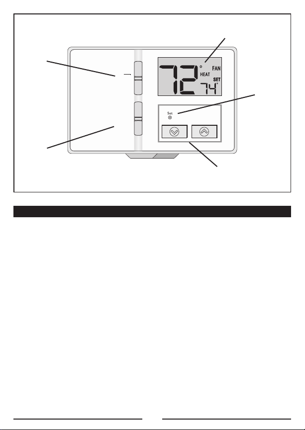
P 1 11
LCD Display Screen
Fan
Mode
Switch
System
Mode
Switch
UP and DOWN Buttons
SYS TEM C OMPATIBILITY:
Th e electri ca l rating fo r this th er mo stat is 1 .5 Am ps p er term in al , w it h a
ma ximum tot al combined l oad of 2. 0A for all te rminals c om bined.
CO MPAT IBLE WI TH :
• Mo st single -s ta ge 24-vol t, he at in g and coo li ng system s
• 1 st ag e heat / 1 stage cool: gas, oil, or e le ctric sys te ms
• Si ng le-stage he at pump sys te ms (witho ut auxiliar y or e mergenc y heat)
• 2- wi re hydr on ic (hot w at er ) zone va lv es
• Mi ll ivolt h ea te rs (inclu ding wa ll h ea ters / ga s firepla ce s)
SET
Button
NOT COM PATI BL E WITH:
• 12 0/ 240 VA C li ne-volt ag e systems ( wi thout a t ra nsformer)
• Mu lt i-stage h ea t pump syst em s (with a ux iliary or e me rg ency he at )
• 3- wi re hydr on ic (hot w at er ) zone va lv es
(a sk your L UX PRO deale r for therm os ta ts to c on tr ol thes e sy stems)
3
Page 4

FEATURES:
• No n- program ma bl e opera ti on
• Li gh ted dis pl ay
• Ke yp ad lock ou t for una ut ho rized u se rs
• Ad ju stable te mp erature d if fe rential / cycl e-rate
• Us er temper at ur e calibra ti on
• Ad ju stable he at /c ool set t em perature li mit stops
• Du al -powered (b at tery and/or 2 4- volt sy st em powered)
• F/ C tempera tu re d isplay
• 5/ 2- minute se le ctable ti me delay fo r equipme nt p rotecti on
TOOLS YO U MAY NEE D:
• Sc re wdriver s
• Wi re Stripp er
• Wi re Cutter
• Dr il l with as so rted dr il l bits (n ew i nstalla ti on s only)
4
Page 5
MOUNT ING LOCATION :
OF
F
On replacem en t install at io ns, m ount th e ne w therm os ta t in plac e of the ol d on e
un less the co nditions li sted belo w su ggest o th er wise. On ne w in stallatio ns ,
pl ease foll ow t hese ge ne ra l guide li ne s:
1. Mount th e thermos ta t on an ins id e wall, about 5 ft. ( 1.5m) abo ve the floo r.
2. Do not l oc ate the t he rmostat whe re air circ ul at ion is po or such as in a corner,
al cove, or beh in d a door th at i s norma ll y left op en .
3. Do not l oc ate the t he rmostat whe re unusual he at ing or co ol ing condi ti ons may
be present, su ch a s: di rect su nl ig ht, a bove a la mp , t el evision , or ra di ator, or on
a wall next t o an exte ri or door o r window.
4. Do not l oc ate in a da mp enviro nm ent, as this c an lead to co rrosion t ha t may
sh orten the rm ostat lif e.
5. If pai nt in g or co ns tr uction wo rk is sti ll o ngoing, cove r th e therm os ta t
co mpletely or wait unt il this wor k is comple te before i ns tallation .
WARNING :
Al l wiring mu st confor m to the lo ca l codes a nd ordinanc es that are i n your
pa rticular lo ca tion.
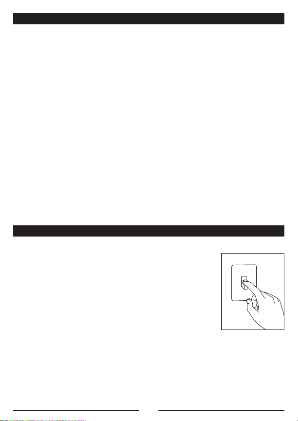
REMOV E OLD TH ERMOSTAT:
1. Turn OFF t he electric it y to all he at ing and c oo ling
co mponents. Do n ot turn t he e lectric it y back on u nt il
al l work is c ompleted.
2. Remove t he front po rt ion of yo ur old th er mo stat to
ex pose the wi ring conn ec tions.
3. Wr it e down th e letters p ri nted near e ach wire te rminal
th at is use d, an d al so the co lo r of ea ch w ire tha t is
co nnected t o it. Self-ad he si ve wire l ab els are a ls o
en close d.
4. Carefu ll y remove th e wires o ne a t a time, and be nd them i n a manner so that
th ey do not f all back in side the wa ll. D o not a ll ow b are wir e en ds to t ou ch
ea ch other.
5. Loosen t he mounti ng s crews f or t he old th er mostat an d carefully r emove it
fr om the wa ll .
5
Page 6
INSTALL T HERMO STAT BASE:
He at
Of f
Co ol
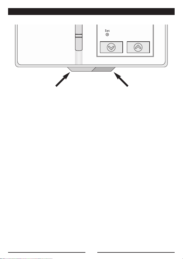
HO USING REL EA SE TABS
(U NDERNEATH BOTTOM ED GE)
1. Strip wi re insula ti on leaving on ly 3/8 in. (9.5m m) bare wir e ends, and cl ean off
an y corrosi on p resent.
2. Fill t he wall o pe ning with n on-combus ti ble insul at io n to prev en t drafts fr om
af fecting t he thermost at ’s normal op er at ion.
3. Separa te n ew thermo st at housing us ing your th umb and i nd ex finger. P ro vide
pr essure in o pposite d ir ections t o the relea se tabs und er the bott om edge of
th e housing .
4. Route th e wires t hr ou gh the op en ing in th e new the rm os tat base pl at e, an d
ho ld the ba se a gainst th e wall. Tr y to line u p the screw h oles from t he prior
th ermostat, and in st all the m ou nting s cr ew s.
5. If the p re vious h ol es cannot b e used, hold t he t hermost at b ase against t he
wa ll so tha t it a ppears st ra ight an d le vel (po si ti on the ba se for be st
ap pe arance) a nd mark f or t he new sc re w holes . Attach th e base to t he wall
us ing the s cr ews provi de d (use th e supplied pl astic anc ho rs if nee de d when
mo unting to a soft mat er ia l such as d ry wall).
6
Page 7

WIRIN G INFORM ATION:
CO NNECTING TH E WIRES:
Wh en attach in g the wir es t o the t he rm ostat, please en su re that t he bare wir e
en ds are he ld AL L the way i nt o the t er mi nal blo ck w hile th e sc rew is be in g
ti ghtened.
WI RING BASE P LATE NOT ICE:
Th is thermo st at model is p art of a fa mily of s im ilar mo de ls that have th e same
ge neral vis ua l appeara nc e. E ve n thoug h th is base p la te may lo ok t he same a s
ba se plates f ro m other m od els, the wir in g connect io ns may ha ve d if ferent
te rminal le tt ers for d if ferent pu rp oses. Pleas e do not in te rc hange t he b ack pla te s
an d/or ther mo stat fron t ha lves of o th er simi la r looking m od els. Doing so m ay
ca use undes ir ed heatin g an d/or co ol in g opera ti on t o occur.
7
Page 8

WI RING DIAG RA M NOT ES :
(I mportant, pl ea se read a ll n otes be fo re connec ti ng wires)
• If t he info rm at io n provi de d in the fo ll owing wir in g diagrams do es not cl early
re present o r ma tch you r sy stem, please r ef er to t he “T EC HN ICAL ASSISTANCE ”
se ction of th is manual , a nd c ontact us b efore r em ov ing any o f yo ur exis ti ng
th ermostat wi ri ng.
• All o f th e dashe d wi res sho wn i n the wir in g diagrams ar e either op tional, or
th eir usage d ep ends up on y our spe ci fi c syste m ty pe or b ra nd . For exa mp le:
Di ag ram #1 sh ow s the fan w ir e as op ti on al. If your s ys tem doe s no t have a
fa n, th an this t er minal w il l not be us ed .
• Term in al letter s shown in bl ac k represe nt typical wi ring applic at io ns.
De pending u po n the bra nd of your sp ecific sy st em or the rm ostat, your te rm in al
le tters may n ot match ex ac tly. Term inal le tt er s shown i n gr ay repr es en t other
po ssible wi ri ng design at io ns that y ou m ight se e on your e xi st ing the rm os ta t
te rminals.
• The o pt io nal “ C” terminal is used for p ow ering the t hermostat b y the 24-vo lt
sy stem, using th e System Co mm on wire . This ca n be used a lo ne , o r in
ad dition to i nstalling b at teries as a backup . NO TE : c on ne cting t he S ystem
Co mmon wire t o the the rm ostat is no t necessa ry f or heating an d cooling t o
fu nction pr op erly.
• If y our old t he rmostat h as b oth a “Y” and “C” wire both p resent, then “C” is
mo st likely a System C om mon wire.
• If y our old t he rmostat h as b oth an “O” and a “B” wire p re sent, then “B” is
li kely a Sy st em Common w ire and m ay be conne ct ed to the “C ” ter mi na l.
Co nnecting a System Co mm on wire t o this ther mo stat’s “ B” te rminal ma y
da ma ge the th er mostat, and al so y our hea ti ng and cool in g system.
• If r eplacin g an old th er mo stat that h as a mechan ic al cl oc k, th er e may b e tw o
wi res label ed as “ C” fo r the c lock power. Tape o ff these wi re s and do no t
co nnect the m to the “C” termin al o f this th er mostat.
8
Page 9

WIRIN G DIAGRA MS:
DIAGR AM SYS TEM T YPE / DE SCRIPTIO N PAGE #
#1 CO NVENTIONA L: HE ATING ONLY ..................................................10
SI NGLE-STAGE
2, 3, or 4 W IRES
#2 CO NVENTIONA L: CO OLING ONLY .................................................11
SI NGLE-STAGE
3 or 4 WIRE S
#3 CO NVENTIONA L: HE ATING AND CO OLING .....................................12
SI NGLE-STAGE
4 or 5 WIRE S
#4 CO NVENTIONA L: HE ATING AND CO OLING .....................................13
TW O-TRANSFO RM ERS, SINGLE- STA GE
5 or 6 WIRE S
#5 HE AT PUMP: HE ATING AND CO OLING .....................................14
NO AUXILIAR Y / EME RG H EAT, SINGL E- STA GE
4 or 5 WIRE S
9
Page 10

2 / 3 / 4 WIRES
CONVENTIONAL, NON HEAT PUMP
1-STAGE, HEAT ONLY
(INCLUDING MILLIVOLT)
NOTE: THE BLACK TERMINAL LETTERS ARE TYPICAL,
GRAY TERMINAL LETTERS ARE BRAND SPECIFIC
W1 4W
X
F
G
RH VR
Factory
RH-RC
Jumper
Wire
Installed
#1
C
FAN
24 V H EAT
TR ANSF ORME R
OPTIONAL
SYSTEM COMMON
HE ATER
10
Page 11

Y1 6Y
A/ C
UN IT
3 / 4 WIRES
CONVENTIONAL, NON HEAT PUMP
1-STAGE, COOL ONLY
NOTE: THE BLACK TERMINAL LETTERS ARE TYPICAL,
GRAY TERMINAL LETTERS ARE BRAND SPECIFIC
X
F
G
Factory
RH-RC
Jumper
Wire
Installed
#2
C
FAN
OPTIONAL
SYSTEM COMMON
RC
V
R
24 V CO OL
TR ANSF ORME R
11
Page 12

Y1 6Y
A/ C
UN IT
4 / 5 WIRES
CONVENTIONAL, NON HEAT PUMP
1-STAGE HEAT AND 1-STAGE COOL
NOTE: THE BLACK TERMINAL LETTERS ARE TYPICAL,
GRAY TERMINAL LETTERS ARE BRAND SPECIFIC
W1
4
W
X
F
G
RH VR
Factory
RH-RC
Jumper
Wire
Installed
#3
C
FAN
24 V
TR ANS FOR MER
OPTIONAL
SYSTEM COMMON
HE ATER
12
Page 13

Y1 6Y
A/ C
UN IT
5 / 6 WIRES
CONVENTIONAL, NON HEAT PUMP
1-HEAT / 1-COOL, WITH TWO-TRANSFORMERS
NOTE: THE BLACK TERMINAL LETTERS ARE TYPICAL,
GRAY TERMINAL LETTERS ARE BRAND SPECIFIC
W1
4
W
X
F
G
R VRH
REMOVE
Factory
RH-RC
Jumper
Wire
#4
C
FAN
24 V H EAT
TR ANSF ORME R
OPTIONAL
SYSTEM COMMON
HE ATER
R
V
RC
24 V CO OL
TR ANSF ORME R
13
Page 14

B*
Y1 6Y
HE AT
PU MP
4 / 5 WIRES
HEAT PUMP SYSTEMS
1-HEAT / 1-COOL,
WITH NO AUXILIARY / EMERG. HEAT
NOTE: THE BLACK TERMINAL LETTERS ARE TYPICAL,
GRAY TERMINAL LETTERS ARE BRAND SPECIFIC
X
F
G
B*
Factory
RH-RC
Jumper
Wire
Installed
For Heat-Pumps
ONLY, Add
Second
Jumper Wire
(Supplied)
#5
C
FAN
OPTIONAL
SYSTEM COMMON
O
RE VER SIN G
VALVE
RC
V
R
24 V
TR ANS FOR MER
* Heat-Pump: if “O” and “B” are both present,
install old “B” wire onto “C” terminal.
14
Page 15

COMPL ETE THE INSTALL:
GAS
(default)
ELEC
JP1
C
G
RH
RC
W
Y
B/O
BATT ERY
IN STALL BATTE RI ES INTO T HE RM OSTAT: Insta ll two bran d new Energ iz er®or
DU RACELL®“A A” s iz e alkalin e (only) ba tt er ies, into the th ermostat’s b at te ry
co mpartment . En su re the ba tt er ies are i ns talled in t he prop er d irectio n.
GA S / ELEC CI RCUIT BOARD OPTI ON (“G” TERMIN AL FA N OP ERATION): This
se tting is a plastic s ho rting cap c al led a j um pe r. T hi s jumper mu st remain
in stalled, and s et to eit he r GAS or EL EC TRIC fo r yo ur syst em t o work pr op erly.
Th is settin g changes h ow y our sys te m’s blower fan ( if applic ab le ) is co nt ro lled
wh ile the t he rmostat i s in HEAT mode , whe n the Fan s witch in th e A UT O positio n.
Th is settin g does not af fect the fa n operati on w hile in C OO L mode.
Wh en set to “G AS ”, th e blower fa n is contro ll ed solely b y the hea ti ng system
it self. Syste ms t ha t would t yp ically us e the “ GAS” setting w ou ld be: natural g as,
pr opane, or oi l fu rnaces, and bo il ers.
Wh en set to “E LE C” , t he blower f an i s contr ol le d direc tl y by the th er mostat. T his
se tting is re quired fo r heating s ys te ms that d o no t contr ol t heir own fa n, su ch as
HE AT PUMPS, and u ni ts that onl y ha ve an ele ct ric-resis ti ve heatin g el ement a s
th e heat so ur ce .
NO TE: I f your bl ow er
fa n does no t operate
pr operly af te r
in stallatio n, mo ve t he
Ga s / Elect ri c option
to the “Electr ic ”
se tting.
15
Page 16

B/ O CIRCUIT B OARD OP TION (FOR H EAT PUMP A PP LICATION S) : T hi s setting i s a
“O” OP TION
(default)
“B” OP TION
JP2
C
G
RH
RC
W
Y
B/O
BATT ERY
pl astic sho rt ing cap ( ca ll ed a ju mp er ) which d et ermines t he operatio n of the
sh ared B/O wi re termin al connecti on . Thi s ju mper mu st r emain i ns ta lled fo r a
He at Pump s ys te m to be a bl e to pr ov id e heating a nd coolin g as needed , and t he
ma jority of h ea t pumps t od ay use th e default “O” setti ng . The s ym pt oms tha t wi ll
oc cur if th is setting is not corr ec t will be : h ea ti ng while in c ool mod e, an d
co oling whi le in heat mo de .
Wh en this i s set to “O” (facto ry d ef ault), the sha re d B/O ter mi nal will be turned
on while in C OOL mode, an d of f in HE AT mo de.
Wh en this i s set to “B” (which i s needed fo r some Rh ee m, Ru ud , a nd Bard h ea t
pu mps), the sh ar ed B/O te rm in al will b e turned on i n HEAT mod e, an d off in CO OL
mo de
16
Page 17

FRONT PAN EL IT EMS:
HE AT / OFF / C OOL, SYSTE M MO DE SWIT CH : Se t this sw it ch to HEAT t o control
yo ur heatin g sy stem, and CO OL t o contr ol y our coo li ng system . The OFF p os ition
wi ll disabl e both the he at ing and c oo ling un it s.
AU TO / ON, FAN MODE S WI TCH: Wh en this s wi tch is in AUTO , the b lo wer fan ( if
pr esent in yo ur system ) will auto ma ti cally c ycle on a nd off by i tself w hi le heating
or cooling is running. When i n th e ON po si ti on, t he blower f an will r un c onstant ly
wi th or wit ho ut a dema nd for heat in g or cool in g, ev en when t he S ystem M od e
sw it ch is i n th e OFF p os it ion.
NO TE: Th e Fan Mod e sw itch only w orks if y ou r system pr ovides a wi re for th e
th ermostat’s “G” wire te rm inal, to contr ol a blower f an . The Fan Mode s wi tch
ha s no effe ct in syste ms that do no t ha ve a bl ow er f an (suc h as a hot wa te r
ra diator sy st em ).
SE T BUTTON: This b ut ton is us ed to acc es s the set up o ptions me nu , a nd other
ad ditional fe at ures.
UP / DOWN B UT TONS: The UP a nd DOWN b ut to ns are us ed to con tr ol the se t
te mperature , or ad ju st any ot he r on-scre en i tems. Ty pi cally, an item th at is
fl ashing ca n currently b e adjuste d.
17
Page 18

SYS TEM C ONFIGURAT ION AND SETUP OP TIONS:
Se tup optio ns for how th e thermos ta t wi ll func ti on , a lo ng with c ho osing y ou r
pa rticular sy stem type , a re p erforme d us ing a m en u on the di sp lay scr ee n.
TO ACCESS T HE SETUP ME NU : Move th e Sy stem Mo de s wi tch int o th e OFF
po sition, and th en hold d ow n th e SET b ut to n for a pp ro xi mately 5 se conds unt il
th e screen ch anges. Th e menu wi ll always s ta rt with i te m #01, and is ad va nced
to each fol lo wi ng item b y a singl e pr ess of th e SET but to n. The op ti ons for e ac h
it em are ch an ged using t he UP or DO WN button s.
IT EM #01 (T EM PERATURE S CALE):
[1 ] (defaul t) Shows al l te mperature v al ues in Fahrenhei t.
[2 ] Shows a ll t emperatur e va lues in C el sius.
IT EM #02 (N OT USED ):
IT EM #03 (N OT USED ):
IT EM #04 (M AX IMUM HEAT SE T TEMP LI MI T):
[1 ] (defaul t) Limit 90 F (32C). Th e maxim um h ea ting se t te mperature i s 90F (32 C)
de grees wit h no heat m od e tempera tu re r estrict io ns .
[2 ] Limit 8 0F (27C). T he maxi mu m heating s et t emperatur e is 80F (2 7C ) degrees .
[3 ] Limit 7 0F (21C). T he maxi mu m heating s et t emperatur e is 70F (2 1C ) degrees .
[4 ] Limit 6 0F (16C). T he maxi mu m heating s et t emperatur e is 60F (1 6C ) degrees .
IT EM #05 (M IN IMUM COOL S ET TEMP L IM IT):
[1 ] (defaul t) Limit 45 F (7C). T he minimu m co oling s et t emperatur e is 45F (7 C)
de grees wit h no cool m od e tempera tu re restri ct io ns.
[2 ] Limit 5 5F (13C). T he maxi mu m cooling s et temper at ur e is 55F (1 3C ) degre es .
[3 ] Limit 6 5F (18C). T he maxi mu m cooling s et temper at ur e is 65F (1 8C ) degre es .
[4 ] Limit 7 5F (24C). T he maxi mu m cooling s et temper at ur e is 75F (2 4C ) degre es .
IT EM #06 (S YSTEM / E QU IPMENT TY PE ):
[1 ] (defaul t) Fn=Furna ce . Thi s is for th e ma jority of h ea ting sy st em s such as a
na tu ral gas f ur nace or h ot water bo il er, that are no t Heat Pump s ys tems.
[2 ] HP=Heat P um p. U se this s et ting if y ou have a H ea t Pump syst em (which u se s
th e outdoor u nit as th e primary hea t so urce). Th e presenc e of either a n “ O” or
“B ” w ir e on yo ur p revious t he rmostat w ou ld typica ll y indicate yo u have a he at
pu mp system . This th er mostat is N OT compatib le w ith hea t pu mps which a lso
ha ve an ele ct ri c heating e le ment as a b ackup h ea t so urce (c al le d A uxiliary /
Em ergency Heat). IMPORTAN T: Wh en s et to “2” for HP, the ci rc uit boa rd
Ga s/Electri c option mu st also be se t to “ELEC”, as d es cr ibed ea rl ie r in th e
“C OMPLETE THE IN STA LL” secti on .
18
Page 19

IT EM #07 (D EL AY TIME):
[1 ] (defaul t) 5 Minute s. Ther mo st at waits 5 mi nutes b ef or e turni ng t he syst em
ba ck on aft er it was l as t run. Th e 5 min ut e setting i s fine fo r mo st applic at io ns ,
an d provide s equipment p rotection b y prevent in g rapid c yclin g.
[2 ] Same op er at ion as ab ov e, bu t reduc ed t o 2 min ut es betwee n st at e chang es i f
de sired.
IT EM #08 (T EM PERATURE S WI NG):
[1 ] (defaul t) Th is is the t ig htest c on tr ol, w hich is p lu s/minus 0 .2 5F (0.1 4C )
de grees fro m the targe t set tempe ra tu re.
[2 through 9] Th es e alter na te v alues m ak e the tem pe ra tu re cont ro l wider w it h
mo re variat io n. E ac h incre me nt al sett in g number ad ds an add it io nal 0.2 5F
(0 .14C) deg re es onto t he initial se tting. [9] is t he wide st c ontrol se tt ing, which i s
pl us/minus 2. 25F (1.25 C) degrees fr om the se t temperatu re .
IT EM #09 (T EM PERATURE C ALIBRATION ):
[0 (zero)] (d efault) At z er o, th er e are n o ch anges m ad e to the ba se room
te mperature m ea suremen t. The ad ju st ment is f ro m as lo w as s ubtract in g
-5 F (-3C) d eg rees from t he room t em perature, to a s hi gh as a dd in g +5F ( +3 C)
de grees to th e room te mp erature. Th e inter na l tempera tu re s ensor i s ac curately
ca librated at t he factor y, an d in most c as es this s et ting sh ou ld not ne ed t o be
al tered.
19
Page 20

OPERATING INST RUCTIONS :
HE ATING AND CO OLING: Basic o pe ra tion of y ou r heating o r cooling s ys tem can
be obtained b y choosin g either HE AT or COOL w it h the Sys te m Mode swit ch . The
te mperature c an be adj us te d using t he UP and D OW N butto ns .
LC D DISPLAY BA CKLIGHT: The di splay scr ee n is ligh te d to assi st viewing at
ni ghttime, or in l ocations wi th low ligh t le vels. A press of a ny button o n the front
pa nel will li ght the d is play for ap pr oximately 1 0 seconds . Any butto n presses
th at occur wh il e the l ig ht is on wi ll reset th e 10-seco nd t imer, causi ng t he scre en
to remain i ll uminated fo r an addi ti on al 10 s ec on ds.
STAT IC NOTI CE : T hi s therm os ta t is prot ec te d against n ormal sta ti c electric
di scharges, ho we ve r to mini mi ze the ri sk o f damagin g th e unit in e xtremel y dr y
we at her, please t ou ch a gr ou nd ed meta l ob ject be fo re touchi ng y our the rm os tat.
20
Page 21

ADVANC ED FE ATUR ES:
KE YPA D LOCKO UT: You can lo ck t he fron t pa nel but to ns to pre ve nt unauth or iz ed
ta mpering o f your ther mo stat sett in gs .
TO LOCK THE KE YPAD: Star t wi th the th er mostat at r es t, an d the dis pl ay backli gh t
NO T illumin at ed . Pr ess the S ET button o ne time t o il luminate th e display s cr een,
th en press an d hold th e SET butto n for at le as t five se co nd s until a p adlock ic on
ap pe ars in th e display s cr een.
TO UNLOCK THE KE YPA D: St ar t with th e th ermosta t at r est, and the d is play
ba cklight N OT illumina te d. P re ss the SE T button on e time to i ll uminate t he
di splay scr ee n, th en pres s an d hold th e SET but to n for at le as t five se co nd s until
th e padlock i con disap pe ar s from th e display s cr een.
SO FTWAR E RE SET: A Soft wa re Reset is used to er ase A LL heating an d cooling
te mperature p ro grams, and t o re turn al l us er- ad justabl e so ftware se tt ings ba ck
to their or ig inal fact or y de fault v al ue s. To perform a S oftware R es et, f irst ensu re
th at the th er mo stat’s Keypa d Lockout i s not enabl ed and then m ove the S ys tem
Mo de switch t o the OFF p os ition. Star t wi th the th er mostat at r es t, an d the
di splay bac kl ight NOT il luminated . Pre ss t he SET bu tt on one ti me to ill um in at e
th e display s creen, then pr es s and h ol d the SET b ut ton for a t le ast fiv e se conds
un til the b ac klight go es out and th e display s creen bec om es fully po pulated w it h
al l segment s visible.
CO MPRESSOR PR OTECT IO N BYPASS: This op ti onal featur e permits t he installe r
or ser vice te ch ni cian to t em poraril y di sable t he b uilt in c om pressor p ro tection
de lays. T hi s is mo st u seful f or d ia gnosing a nd testin g th e heating a nd coolin g
sy stems aft er installa ti on is com pl et e, an d shoul d no t be us ed d uring n or ma l
op eration. To activ at e this featur e, fi rs t ensure th at the th er mo stat’s Keypa d
Lo ckout is no t enabled a nd then m ov e the Sys te m Mode sw it ch to the O FF
po sition. Sta rt w ith the t he rmostat a t re st , a nd the di sp la y backl ig ht NOT
il luminated . Pre ss a ny button o ne time t o il luminate th e display s creen, then
pr ess and h ol d both th e UP and DO WN b uttons to ge ther at t he s ame tim e fo r at
le ast five se conds. NOTE : the re w ill no vi su al conf ir ma ti on on t he d isplay sc re en
wh en this f ea tu re beco me s activated , howev er you shou ld be able to turn the
co oling sys te m on and of f without a ny protec ti on delays b ei ng impo se d. All
co mpressor pr otection de lays (in al l modes o f operation ) wi ll be d is ab led for 5
mi nutes. Af ter the 5 -m inute d ur at io n has e xp ir ed, t he ther mo st at will r et urn to
no rmal oper at io n autom at ic al ly.
21
Page 22

BATTERY REPL ACEME NT:
Th is thermo st at is power ed b y two “AA” A lk al ine batte ri es . The b at teries sh ou ld
be replaced AT LE AS T once pe r year to e ns ure relia bl e operation ( or sooner i f the
ba tt er y icon or “LO BAT T” ap pe ars in th e display s cr een). T he batteries ar e
lo ca ted on th e back of t he thermo st at ’s circuit b oa rd. T he f ront po rt io n of th e
th ermostat ca n be remo ve d from th e ba ck half b y using t he h ousing re le ase tab s
on the bott om edge of th e thermos ta t housing .
Wh en instal li ng new ba tt er ies, we reco mm en d using o nl y brand n ew Energi ze r
®
or DURACELL®, “AA” size alka li ne batterie s. P le ase obs er ve t he polari ty
ma rkings sh ow n in the ba tt er y compartme nt to ensur e proper in st allation. W hen
fi nished, line u p the fro nt o f the t he rm ostat to th e base, and fi rm ly press to ge ther
to securely l at ch the fr on t and b ac k halves to ge ther pr op er ly.
TECHN ICA L ASSISTA NCE:
If you have a ny p roblems i ns talling o r using t hi s thermos ta t, pl ea se carefu ll y and
th oroughly re view the in struction m anual. If yo u re quire a ss is tance, pleas e
co ntact our Tec hn ical Assista nc e departm en t at 856-23 4- 88 03 duri ng r egular
bu siness ho ur s between 8 :00AM and 4 :30PM Eas te rn Standa rd Time, Monday
th rough Friday. You can also r eceive te ch nical ass is tance onl in e anytime d ay or
ni ght at ww w.lux pr op roducts .c om . O ur websit e of fers yo u tr oublesh oo ti ng guid es ,
an sw ers to th e most co mm on techni ca l questio ns , a nd a lso per mi ts you to e ma il
yo ur questi on s to our te chnical s up port staf f at your c on ve nience.
22
Page 23

LIMIT ED WARRANTY:
If this uni t fails bec au se of def ec ts in mat er ia ls or w or km anship wi th in thre e
ye ars of th e da te of o ri gi nal pur ch as e, LU X will, at its o pt ion, repair or replace it .
Th is warran ty does not c over dama ge b y accid en t, mi su se, o r failu re t o follo w
in stallatio n in structi on s. I mp lied wa rr an ties ar e li mited i n du ra tion to t hr ee year s
fr om the da te o f origi na l purchas e. S om e states do n ot allow li mi ta tions on ho w
lo ng an imp li ed warran ty lasts, so t he a bove li mi ta ti on may no t ap ply to yo u.
Pl ease retu rn malfunct io ning or d ef ective un it s to the lo ca tion fr om w hich th e
pu rchase wa s made, along wi th proof of p urchase . Pl ea se refer to “T EC HN ICAL
AS SISTANCE” befor e returning t hermostat. Purc ha ser assum es all risk s and
li ability f or incident al and cons eq uential d am ag e resul ti ng from i ns ta llation a nd
us e of this u nit. Some s ta te s do not al lo w the exc lusion of i ncident al o r
co nsequenti al damages, so t he a bove ex clusion m ay not appl y to you. T hi s
wa rranty gi ve s you spe ci fic legal r ights and y ou may al so have oth er r ights,
wh ich vary fr om s tate to s ta te . Appli ca bl e in th e U. S.A. and Can ad a only.
MERCU RY WAR NING AND RECYCLI NG NOTICE:
Me rcur y is a ha za rdous s ub st ance. Many sta te s ha ve laws
re quiring t he proper d is posal of me rcur y therm os ta ts.
If your new t hermostat i s replaci ng a n older t he rmostat t ha t
mi ght conta in mercury, please vi si t
ww w.t he rmostat -r ecycl e. org to lear n ho w and whe re to
di spose of yo ur old th er mostat. On the w eb site yo u ca n enter y ou r ZIP c od e to
lo ca te the ne ar est loc al d rop-off p oi nt to r ecycl e yo ur old th er mostat. If you a re
no t sure wh et her your ol d thermos ta t contain s me rcury, t he websit e al so
pr ovides in fo rmation a nd g uidelin es t o help yo u determi ne w hether it d oes. If you
ar e unable to access t he website, yo u ma y call th e T he rm ostat Rec yclin g
Co rporation a t 1- 888-266 -0 55 0 for g ui da nce reg ar di ng the pr op er hand li ng and
di sposal of y our old m er cury thermo st at .
23
Page 24

Fa n
Au to
On
He at
Of f
Co ol
ww w.luxp roprodu cts.com
85 6-234-8 803
24
 Loading...