

Lux Products LUXPRO PSPHA732 Series Installation And Operating Instructions Manual
CAUTION:
Your thermostat is protected against
normal static electric discharges. To
minimize the risk of damaging the unit in
extremely dry weather, touch a grounded
metal object before touching your
thermostat.
4. INSTALLATION
4.1 TOOLS REQUIRED
• #1 Phillips screwdriver (small)
• Drill with 3/16-in. (4.8mm) bit
• Wire stripper/cutter
4.2 LOCATION
• On replacement installations, mount the new
thermostat in place of the old one, unless the
conditions listed below suggest otherwise. On
new installations, follow the guidelines listed
below.
• Locate the thermostat on an inside wall, about 5
ft. (1.5m) above the floor, in a room that is used
often.
• Do not locate where air circulation is poor, such
as in a corner or an alcove; or behind an open
door.
• Do not install it where there are unusual heating
conditions, such as: in direct sunlight; near a
lamp, television, radiator, register, or fireplace;
near hot water pipes in a wall; near a stove on
the other side of the wall.
• Do not locate in unusual cooling conditions,
such as: on a wall separating an unheated room;
or in a draft from a stairwell, door, or window.
• Do not locate in a damp area. This can lead to
corrosion that will shorten thermostat life.
• Do not install the unit until all construction work
and painting has been completed.
WARNING:
• Read instructions carefully before
removing any wiring from an existing
thermostat.
• Label wires before they are removed.
• When removing wires from their
terminals, ignore the color of the wires
since they may not comply with any
standard.
4.3 REMOVAL OF OLD UNIT
1. Switch electricity to the furnace and air
conditioner OFF; then proceed with the following
steps.
2. Remove cover from old thermostat. Most are
snap-on types and simply pull off. Some have
locking screws on the side. These must be
loosened.
3. Note the letters printed near the terminals.
Attach labels (enclosed) to each wire to
identification. Label and remove wires one at a
time. Make sure the wires do not fall back inside
the wall.
4. Loosen all screws on the old thermostat and
remove it from the wall.
4.4 MOUNTING
5. Strip insulation 3/8 in. (9.5mm) from wire
ends and clean off any corrosion.
6. Fill wall opening with non-combustible
insulation to prevent drafts from affecting the
thermostat.
7. With each thumb on a release tab at the
bottom of the body, and fingers over the top of
the unit, release the unit from its base plate by
squeezing the tabs into the body.
8. Separate the unit from its base plate by pulling
the body outward at its bottom.
3
1. COMPATIBILITY
Your
PSPHA732
is compatible with Heat Pumps
Up to 3 Stages of Heat and 2 Stages of Cooling.
This includes Auxiliary and Emergency Heat. It
cannot be used with 120 volt heating systems or
3 wire zone valves. Ask your dealer for other
LUXPRO thermostats to control those systems.
2. FEATURES
• Heating and Cooling
• Electronic
• Programmable
• 7 Day Programming (Each day can be different)
• Auxiliary and Emergency Heat Indicators
• Programming Copy Button
• Large Display
• Electro-luminescent Display Backlight
• Clean Cycle™ IAQ Independently Programmable
Fan
• ENERGY STAR
®
Compliant
• 4 Periods Per Day
• Temporary Override 1-4hr (CAT24 Compliant)
• Hold
• Optional Smart Recovery
• Easy Programming with LUX Speed Dial
®
• Programmable Filter Monitor and Indicator
• Energy Usage Monitor
• Battery Free Nonvolatile Memory For All
Programs And Settings
• Battery or System Powered with Battery Backup
• Batteries Included (2 AA)
• Auto-Changeover
• Programmable Auto-Changeover Dead band
(1˚ to 6˚ F) (1˚ to 3˚ C)
• Keyboard Lockout
• Temperature Offset (User Calibration)
• On Screen Low Battery Indicator
• F/C Temperature Display
• 12/24 Hour Clock
• 2 or 5 Minute Short Cycle Protection
• 1 Minute Optional Residual Fan
• Multi-Stage Adjustable Temperature Differential
/ Cycle Rate
• Terminals: E, C, Y1, R, Y2, W, B, O, G
3. ELECTRICAL RATINGS
• 30V maximum (24VAC nominal)
• 1.5A maximum per terminal
• 2.0A terminal sum
2
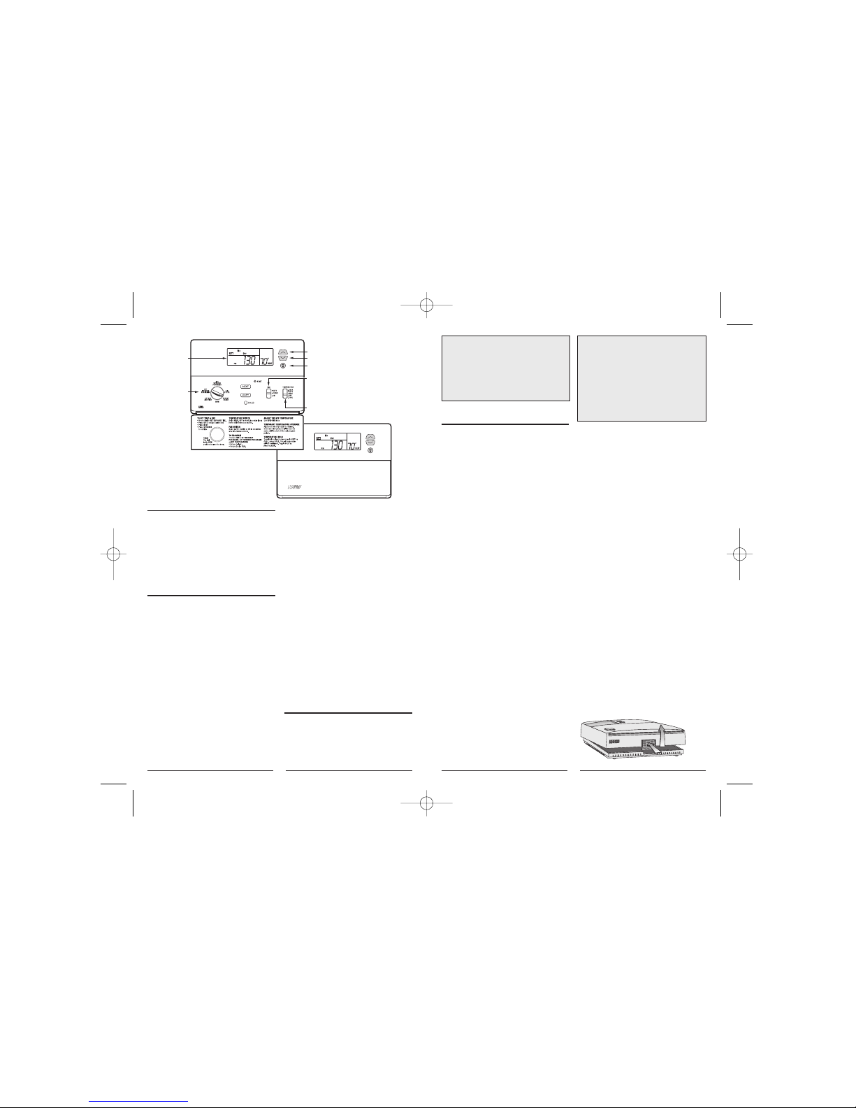
PSPHA732
EASY
PROGRAMMING
WITH
LUX SPEED DIAL
®
UP
LARGE
BACKLIT
DISPLAY
DOWN
LIGHT
MODE SWITCH
IAQ
INDEPENDENTLY
PROGRAMMABLE
FAN
PSPHA732
14704_PSPHA732_MANUAL_16pg.qxd 2/11/05 12:25 PM Page 2
NOTE: If you have an electric system and
the blower does not operate after
installation, verify that the electric/gas
option in installer set up is set to Electric,
see SETUP OPTIONS.
18. Your installation is now complete.
5. OPERATING BASICS
5.1 UP/DOWN CHANGE KEYS
• These are the two upper keys, just right of the
units display. They are used to adjust set
temperatures, and make other setting changes.
• Pressing these keys once will adjust a setting
one step in the associated direction.
• If there are many choices for a value, usually
that setting will advance while holding one of
these keys. Some settings though, must be
changed one press at a time.
5.2 SET DAY AND TIME
To set the correct time after the unit has lost
power or after reset:
• Open the door on the front of the thermostat.
• Rotate the dial to
SET DAY/TIME
. The
abbreviation for the day of week will flash.
• Use the UP key to advance to the current day.
• Press
NEXT
to adjust the time. Time will flash.
• Use the
UP/DOWN
keys to set the time.
• Pressing
NEXT
again will toggle from Set Time
to Set Day, or vice versa.
• Return the dial to its
RUN
position.
5.3 TEMPERATURE CONTROL MODES
When a unit has first been powered up with the
dial in the
RUN
position, your thermostat will
begin to control your heating and/or air
conditioning system according to it’s default
ENERGY STAR
®
approved program. There is a 5position slide switch to change temperature
control modes. Slide the switch to the mode you
would like to use.
5.4 EMERGENCY (EMER)
• Use EMERGENCY position on slide switch to
active your emergency heating. You will see
"EMER HEAT" appear in the display. Press
temperature UP or DOWN keys until your
desired temperature is displayed in the HEAT SET
area of the display. "EMER HEAT" will flash if it
is activated and running.
• Putting your thermostat in this mode will
disable the other 2 stages of heating. (Your heat
pump will be disabled).
• The 3rd stage of heat will deenergize as soon as
the temperature setpoint is reached. The letters
"EMER" will disappear.
5.5 AUTOCHANGE (AUTO)
• Use AUTOCHANGE mode to allow your
thermostat to switch between HEAT and COOL
modes automatically. Slide the mode switch to
AUTO
and
AUTO CHANGE
will be displayed
above the set temperature. You can determine
whether your thermostat is in HEAT or COOL
mode by whether HEAT or COOL is visible in the
set temperature area of the units display. Initially
HEAT or COOL may not be active until a
determination is made that HEAT or COOL is
necessary.
• The programmed temperature for a given mode
will be used as the set temperature for that
mode.
• Pressing the
UP/DOWN
keys at the same time
will force the unit to change modes and make the
programmed set temperature the new set
temperature.
5.6 HEAT
• Use HEAT mode to control your furnace and
warm your home.
• In HEAT mode,
HEAT
is displayed right of the
set temperature.
•
HEAT
will display solid if there is no load.
• While the 1st stage of heating is active,
HEAT
will flash.
5
CAUTION:
• Be careful not to drop the unit or disturb
electronic parts.
• Leave the door closed while the body is
being removed from the base.
9. Route the wires through the open areas in the
base plate above the terminals. Hold the base
against the wall, with the wires coming through.
Position the base for the best appearance (to
hide any marks from an old thermostat). Attach
the base to the wall with the two screws
provided.
NOTE: If you are mounting the base to a
soft material like plasterboard or if you are
using the old mounting holes, the screws
may not hold. Drill a 3/16-in. (4.8mm) hole
at each screw location, and insert the
plastic anchors provided. Then mount the
base as described below.
4.5 WIRING
• Using the terminal descriptions below, wiring
diagram on page 14, and your labels, determine
the appropriate wiring for your system.
• Also Refer to the Heat Pump Cross-reference
Chart on page 15.
• If you are unsure or need assistance, call the
LUX Technical Assistance Dept. (see
TECHNICAL
ASSISTANCE
.)
4.5.1 TERMINAL DESCRIPTIONS
• See drawing on page 16 showing layout of
terminals.
G The fan terminal is live at any time the
thermostat attempts to turn the system fan or
blower on.
O Live at any time the unit is in Cool mode.
B Live at any time unit is in Heat Mode.
W Active while the thermostat is calling for
auxiliary 3rd stage of heat.
Y2 Active while calling for a 2nd stage of
heating/cooling.
R Transformer, Provides Power
Y1 Active while calling for a 1st Stage of
heating/cooling.
C Use of this terminal allows the unit to be
system powered rather than battery powered.
E This terminal is active when the thermostat is
calling for Emergency Heat.
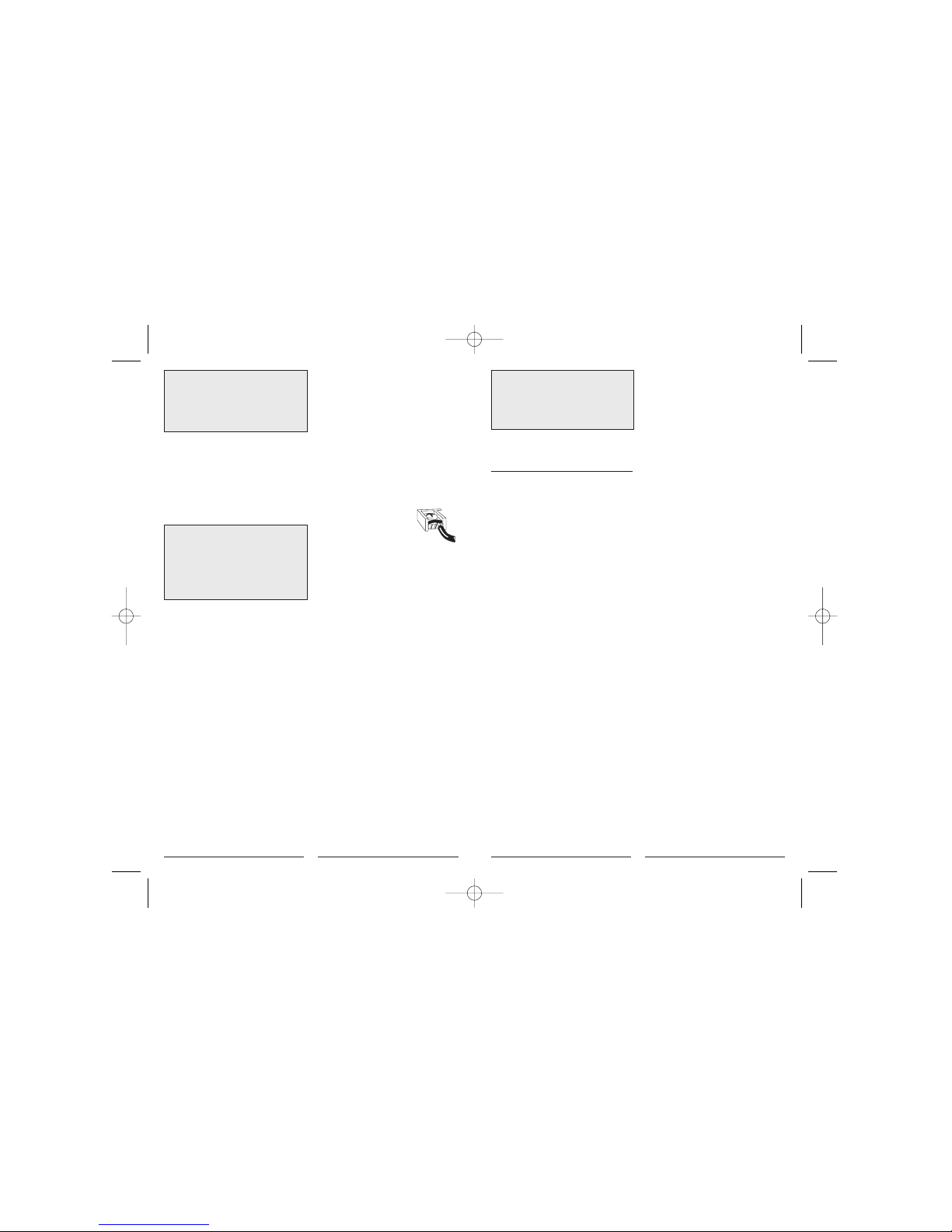
4.5.2 CONNECTING THE WIRES
10. Loosen wire clamp screws
just enough to slide wire under
the black top part of the clamp.
11. Connect stripped wire ends,
by trapping it between its black clamp and brass
terminal. Then tighten its terminal screw.
12. Tape the ends of any unused wires.
4.5.3 COMPLETING YOUR INSTALLATION
13. Install two new Energizer®or DURACELL
®
"AA" size alkaline batteries at this time. For
instructions, refer to BATTERIES/MAINTENANCE.
14. Configure your thermostat at this time. Refer
to SETUP OPTIONS.
15. Install your thermostat on its base. To do
this, hang the top of the unit by the tabs on the
base, then snap the bottom of the unit into place.
Do not use unnecessary force. If the body does
not snap into place easily, remove the body, rehang it from tabs and try again.
16. Turn the power back on to your heating
and/or air conditioning system.
17. Verify that the system and its fan are
operating properly. When set to a high
temperature, the heating system should provide
warm air after a short time. Likewise, a cooling
system should provide cool air after a short time.
Usually sound from the furnace and air
conditioning units can be heard while they are
running. The rush of moving air should be heard
within a short time after either has been started.
4
14704_PSPHA732_MANUAL_16pg.qxd 2/11/05 12:25 PM Page 4
5.12.3 CLEAN CYCLE™
• LUX’s Clean Cycle™ allows you to program a
forced air system to flow air through your
system’s filter, cleaning the air in your home,
even when heating or cooling is not being
utilized. In CLEAN mode the fan maintains the
programmed minimum run time; it may run
additional time as required to maintain
temperature control. The program used avoids
additional fan time when the minimum run time
has been met over the last hour through
temperature control. Minimum fan run times are
met by running one-third the hourly requirement
at twenty-minute intervals. The default minimum
fan run time is 15 minutes per hour.
5.13 DISPLAY ILLUMINATION
For visibility in the dark, your LUX thermostat
incorporates an attractive electro-luminescent
display backlight.
• Press the light bulb button right of the display
to illuminate.
• Pressing this or other buttons will keep the
display illuminated.
5.14 AUDIBLE BEEP
When a key is pressed, the thermostat will emit
an audible beep. The beep will terminate within
1
⁄
2
second while a button is held.
6. PROGRAMMING
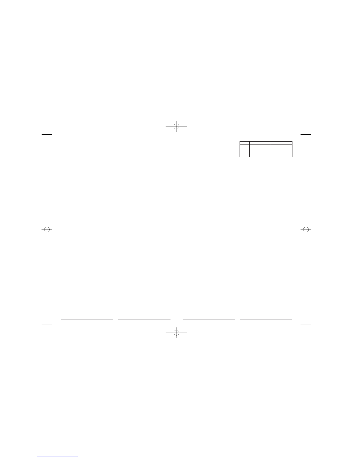
6.1 DEFAULT TEMPERATURE PROGRAM
As supplied from the factory, the following
ENERGY STAR
®
approved program will be used
for temperature control in RUN MODE. This
program and all other software settings may be
restored to their default values via a SOFTWARE
RESET.
6.2 EDITING HEAT OR COOL PROGRAMS
You can change any preset times and/or
temperatures to suit your schedule for each day
of the week (7 Day Programming). The four
periods each day are named Morning (MORN),
Day, Evening (EVE), and Night (NITE).
6.2.1 WEEKDAY PROGRAMMING
To change the HEAT or COOL program:
• Set to
HEAT, COOL
, or
AUTO
with the mode
switch.
• Rotate dial to
SET WEEKDAY PROGRAMS
.
PROGRAM, Mo, MORN
and
START AT
will be
displayed, with the Set Time flashing.
Programming is performed in the following
order.
1 Mo Morn Start Time
2 Mo Morn Heat Set Temperature
3 Mo Morn Cool Set Temperature
4 Mo Day Start Time
5 Mo Day Heat Set Temperature
6 . . . and so on until Fri Nite is fully
programmed at which point pressing NEXT again
will begin the list at Mo Morn Start Time.
• Use the
UP/DOWN
keys to change the start
time for this period. Press
UP/DOWN
buttons to
change the time in 15-minute increments. Hold
UP/DOWN
button to change the time at rate of
60 minutes/second.
• One period ends at the start time of the next
period. The end of one period may not be any
closer to the beginning of the next period than
one 15-minute increment. Moving a start time
too close to the next start time results in the
latter time being pushed ahead too. Press
NEXT
7
• If a second stage of heat is called for, the
flashing rate of
HEAT
increases
• If the 3rd stage of heat activates, the display will
also flash "AUX " in addition to HEAT flashing.
5.7 COOL
• Use COOL mode to control your air conditioner,
cooling your home.
• In COOL mode, COOL is displayed right of the
set temperature.
• COOL will display solid if there is no load.
• While the 1st stage of cooling is active, COOL
will flash.
• If a second stage of cooling is called for, the
flashing rate of COOL increases
5.8 OFF
• Slide the MODE switch to
OFF
when no heating
or cooling is desired. Heating and cooling will be
disabled, and the set temperature side of the
display will be empty.
5.9 DEFAULT PROGRAM
• As supplied from the factory, your thermostat
will use its default ENERGY STAR
®
approved
program for temperature control. This program
and all other settings may be restored to their
default values via a SOFTWARE RESET. Please
refer to DEFAULT TEMPERATURE PROGRAM for
program times and temperatures.
5.10 HOLD
Hold is the simplest method to maintain fixed set
temperatures.
• Press
HOLD
once to enter permanent
temperature HOLD while in RUN or OVERRIDE.
HOLD
will be displayed above the set
temperature in the display.
• Pressing this button again will toggle HOLD off
and return to RUN and the programmed set
temperature.
• Changing system mode or rotating the SPEED
DIAL
®
will also cancel a HOLD.
5.11 OVERRIDE
During RUN, set temperatures may be
temporarily altered from their programmed
values. Immediately after a set temperature has
been altered, the 2-hour default duration may be
adjusted within the range from 1 to 4 hours. The
temporary set temperature(s) will be used for the
duration of the OVERRIDE.
• Press either the UP or DOWN key. The current
modes set temperature will begin to flash.
• Adjust the set temperature as desired.
• After a few seconds, the default 2-hour duration
will flash in the time area of the display.
• Adjust the duration in 15-minute increments,
from between 1 to 4 hours.
• When the duration stops flashing, the
OVERRIDE has been initiated and the Set
Temperature side of the display will show
OVERRIDE
.
• The adjust temperature will remain the set
temperature in the current mode for the duration
of the OVERRIDE. Then temperature settings
return to their program values.
• OVERRIDE may be cancelled by initiating a
HOLD and then canceling it, changing the
position of the mode switch, or rotating the
SPEED DIAL
®
.
5.12 FAN MODES
• The FAN switch controls which of three fan
modes your thermostat is to use. These modes
are AUTO, CLEAN and ON.
5.12.1 AUTO
• AUTO mode runs the fan only to fulfill your
heating and cooling requirements.
5.12.2 ON
• ON mode runs your system fan continuously.
6
Morning
Day
Evening
Night
6:00 AM 70
0
F (210C)
8:00 AM 62
0
F (170C)
6:00 PM 70
0
F (210C)
10:00 PM 62
0
F (170C)
6:00 AM 78
0
F (260C)
8:00 AM 85
0
F (290C)
6:00 PM 78
0
F (260C)
10:00 PM 82
0
F (290C)
PERIOD HEAT MODE COOL MODE
14704_PSPHA732_MANUAL_16pg.qxd 2/11/05 12:25 PM Page 6
 Loading...