

Page 1
WTPSCE Assembly
www.luxorfurn.com
www.hwilson.com
Parts List
1. (4 each) 14" or 16" Grooved Legs
2. (2) Back Panels
3. (2) Left Side Cabinet Door Panels
4. (1) Short Front Panel
5. (4) Casters
6. (1) Upper Right Panel
***READ INSTRUCTIONS BEFORE BEGINNING ASSEMBLY
***BACK & FRONT OF SHELVES ARE 24"W, SIDES ARE 18"W
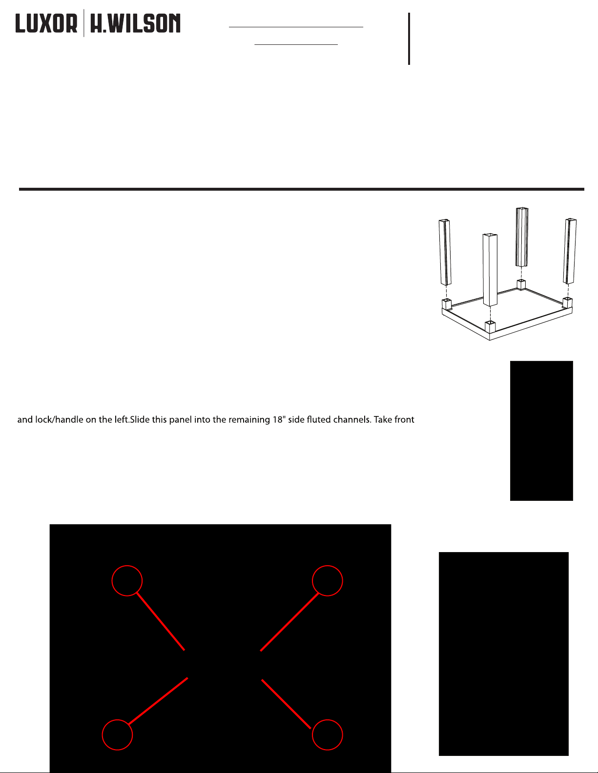
STEP 1: Place the four 16" uted legs over the corner posts (bosses) of the bottom shelf so that
the channels face each other. Use a rubber mallet to tap legs into place. Make sure that legs are
even and fully seated. (FIGURE 1)
STEP 2: Hold the Interior Shelf between the four legs at the desired height. Mark where you want
the shelf to sit. Hold brackets up to these marks and drill two pilot holes on the inside of each leg.
(The holes in the legs will be towards each other along the 24"W side of the shelf.)
The adjustable shelf brackets will be attached to these holes. Attach brackets as shown in Figure 2
using 2 screws per bracket.
**Make sure to leave 2 of the brackets on one of the 24" sides loose for inserting the cabinet
panel. This 24" side will be the 'Front' of the cart.
7. (1) Right Side Cabinet Door Panel (lower) 13. (1) Steel Drop Down Shelf
8. (1) LCD Projector Shelf Assembly (Box T-POS) (Box TDDS)
9. (1) Keyboard Assembly with Hardware (Box TKS)
10. (1) Electrical Assembly with Hardware
11. (1) EACH top shelf (handle), middle shelf (8 bosses) & bottom shelf (4 bosses)
12. (1) Interior Shelf & (4 Brackets with Hardware)
Instructions
Tools Required
-
Rubber Mallet
-
Phillips Screwdriver
-
Drill + Drill Bit
Figure 1
10/
17/13
Step 3: LOWER CABINET- Locate back panel (back panels have moderate ventilation holes, are
24"W and do not have doors) and slide down into grooves of the 2 back legs. Slide lower left side
panel into left front & back leg grooves (Left Panels are smaller cabinet doors with the hinges on
the left/lock & handle on the right.) Lower Right Panel is a cabinet door with hinge on the right
panel (largest cabinet door) and slide into place with the lock positioned so that it is
under the handle. You can now nish tightening the shelf brackets and put your adjustable shelf
on brackets. (Panel sliding into channel shown in Figure 3. Upper right panel shown in photo.)
STEP 4: Take middle shelf and place onto legs so that the bosses are tting into the holes in the
top of the legs. Be sure that the ribbed side is facing down. Push shelf down as far as you can by
hand. Gently tap with mallet if necessary.
Front
Figure 2
Figure 3 shows how to insert panel into
Upper right panel shown.
channel.
Attach brackets
to legs as shown
1
Page 2
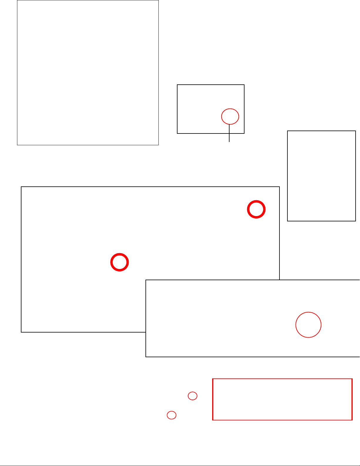
Figure 5
STEP 5 - Assemble LCD Shelf & Brackets.
First you must separate the rails. This is
done by extending the rails out until you
see a small black plastic lever. Depending
on how you are holding the assembly,
you will push the lever up or down until
the rails release. Do this for both rails.
(See Figure 5)
STEP 6: Mark hole pattern onto middle
shelf by holding LCD shelf assembly in
position. If you like, you may pre drill into
the middle shelf. The LCD projector shelf
will attach here when built. (See Figure
4 (previous page) for placement- do not
put legs on or put panels in yet)
You will then attach the brackets to the outer part of the rails,
Lever
two brackets per rail. Attach with the included hardware to the outermost holes on the outside of the
rails. One hole is a bit tricky to get to and you will have to adjust the sliding rail (see left) and attach
through a hole on the sliding rail. Make sure that you are attaching the brackets so that the rail will be
attached to the shelf as shown in Figures 7, circled in red.
Figure 7
Figure 8
Figure 6
You may then slide the
LCD Projector Tray back
onto the rails. Slide in
and out a few times to
make sure everything
is secure.
Figure 9
2
STEP 7 - The Keyboard assembly needs to be attached
to the top shelf. Turn the top shelf upside down.
Line the holes in the metal bracket up with the four
small holes on the underside of the top shelf. Attach
with screws.
Page 3

STEP 8- Take remaining legs and place over bosses on middle shelf.
Left Panels are smaller cabinet doors with
the hinges on the left/lock & handle on the
right.
Top Front Panel is shorter than all
other panels with no perforations
LCD Pullout Shelf
Brackets attach to
top of middle shelf.
Adjustable shelf
Back Panels have moderate perforation
and are interchangable top and bottom
Lower Front Panel is the largest
cabinet door
STEP 9: Put 2 side and rear panels
into channels on legs as shown in
photos on this page.
Top Right Panel (right)
has heaviest perforation.
The electrical can be
installed on this panel.
Follow enclosed electrical
assembly instructions.
This can be done at any
time, but will be easiest
before top shelf encloses
cabinet. See video for
further placement options.
Lower Right Panel is a
cabinet door with hinge on
the right and lock/handle
on the left.
3
Page 4

STEP 10 - Take top shelf assembly (below) and place onto legs
so that the bosses are tting into the holes in the top of the legs
and handle is to the left. The keyboard tray will be accessible
through the short panel. Be sure that the ribbed side is facing
down. Push shelf down as far as you can by hand. Gently tap
with mallet if necessary. (See photo right)
Top Shelf Assembly
The drop down shelf attaches to the right side legs
STEP 11: Hold TDDS up to upper legs on right side of cart FLUSH WITH THE TOP
OF THE SHELF. Mark where to pre drill holes for drop down shelf attachment
with punch if desired. Turn unit on it's side and attach the brackets with screws.
Turn unit right side up.
Finished Cart
STEP 12: Turn cart upside down on a level and rm oor surface.
Insert the stems of the 4 casters into the holes in the underside
of the bottom shelf, locking casters in the front 24"W side. Tap
casters into socket with rubber mallet until fully seated. Turn
4
right side up.
 Loading...