

Page 1
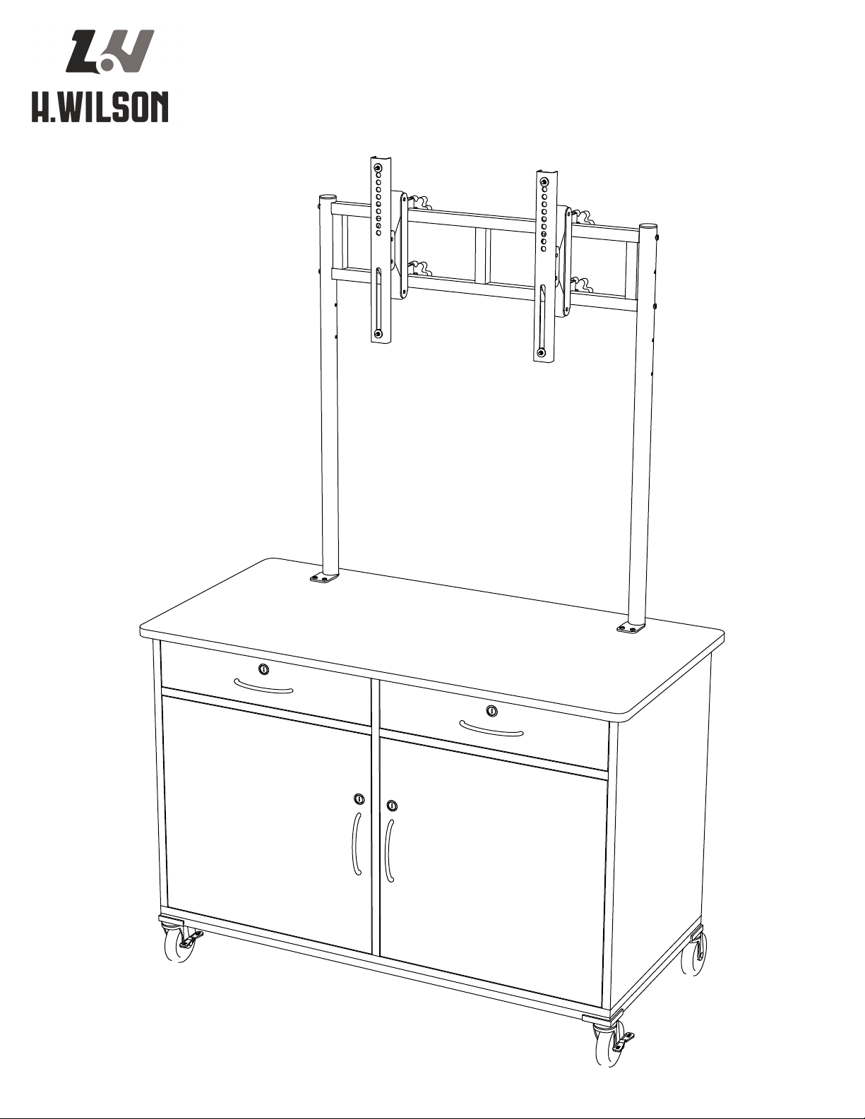
WPVC65E Assembly Guide
Page 2
WPVC65E Assembly Guide
Wood Panel List:
Vertical Divider
1.
Horizontal Divder x 2
2.
Back
3.
Right Side
4.
Left Side
5.
Bottom
6.
Top
7.
Drawer Front x 2
8.
Drawer Left Side x 2
9.
Drawer Right Side x 2
10.
Drawer Bottom x 2
11.
Drawer Back x 2
12.
Left Door Panel
13.
Right Door Panel
14.
Adjustable Shelf Panel x 2
15.
Metal Part List:
Vertical Tubes x 2
16.
Horizontal Support
17.
Adjustable Tilt Brackets x 2
18.
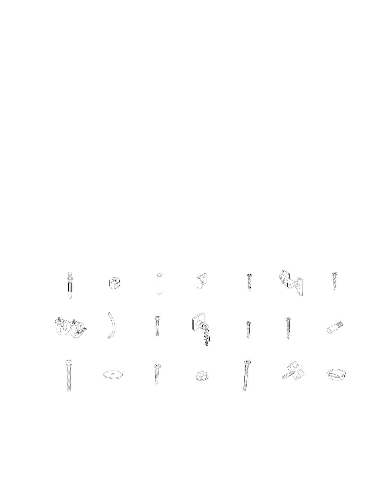
Cabinet Hardware:
A.
Metal Dowel x 36
B.
Cam x 36
C.
Wooden Dowel Pin x 28
D.
Lock Catch x 4
E.
Lock Catch Screw x 8
F.
Door Hinge x 4
G.
#8 x 1/2” Wood Screw x 24
H.
Casters x 4 (2 w/ Brake)
I.
Handle x 4
J.
Handle Screw x 8
K.
Lock and Key Pack x 4
L.
Lock Screw x 16
M.
Drawer Screw x 8
N.
Shelf Pin x 8
O.
Long M8 Bolt x 2
P.
M8 Washer x 2
Q.
Short M6 Allan Bolt x 4
R.
M6 Nut x 4
S.
Long M6 Allan Bolt x 4
T.
Knob x 4
U.
Grommet x 2
TV Hardware:
M5 x 16mm Phillips Bolt x 4
M6 x 16mm Phillips Bolt x 4
M8 x 35mm Phillips Bolt x 4
M6 Washer x 4
M8 Washer x 4
M8 Double Washer x 4
Tools Included:
Caster Wrench
Allan Wrench
Tools Required:
Phillips Screw Driver
A. B. C. D. E. F. G.
H. I. J. K. L. M. N.
O. P. Q. R. S. T. U.
1
H. Wilson Company - Phone: 800.245.7224 | Email: sales@hwilson.com | Web: www.hwilson.com
APRIL 2011
Page 3
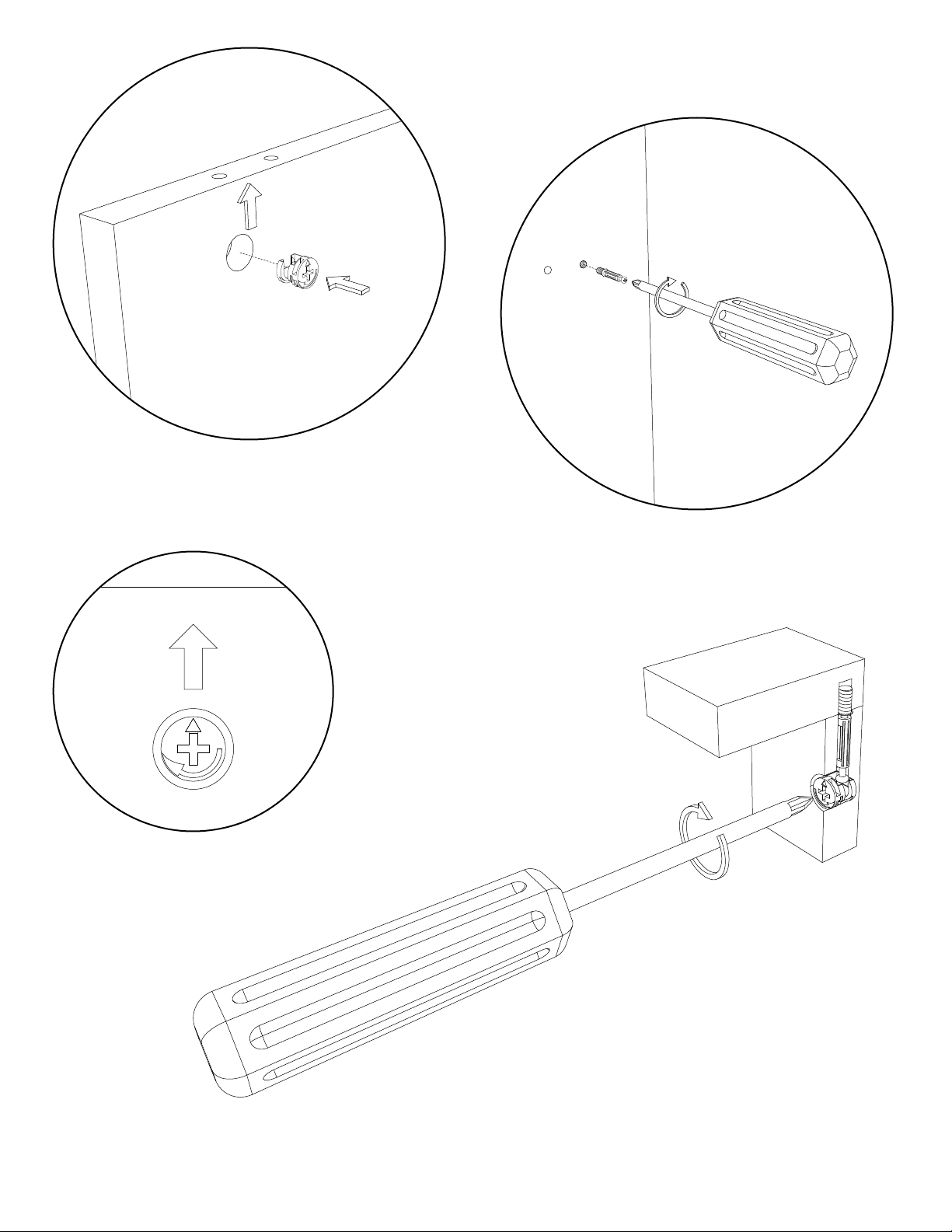
The small arrow on the cam faces toward the outside edge
Screw the metal dowel into the threaded hole
After the panels are placed together,
Turn the cam 90 degrees clockwise
to lock the dowel and cam together.
2
H. Wilson Company - Phone: 800.245.7224 | Email: sales@hwilson.com | Web: www.hwilson.com
APRIL 2011
Page 4
C
E x 2
A
A
B
A
C
B
D
C
B
A
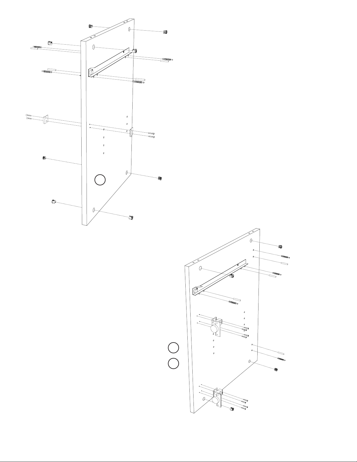
Part List:
1
B
C
Panel 1 - Vertical Divider
A x 8 - Cam
B x 8 - Metal Dowel
C x 8 - Wooden Dowel
D x 2 - Lock Catch
E x 4 - Lock Catch Screw
A
A
Part List:
2
Panel 4 - Right Side
Panel 5 - Left Side
A x 8 - Cam
B x 8 - Metal Dowel
C x 8 - Wooden Dowel
F x 4 - Door Hinge
G x 16 - Wood Screw
D
E x 2
1
A
A
Install 4 cams, 4 metal dowels and
4 wooden dowels. Install the 2 lock
catches with the 4 lock catch screws.
Set the vertical divider panel aside.
A
C
A
C
B
B
C
B
Per Panel - Install 4 cams, 4 metal dowels
and 4 wooden dowels. Install 2 door
hinges with 8 wood screws.
Set the side panels aside.
H. Wilson Company - Phone: 800.245.7224 | Email: sales@hwilson.com | Web: www.hwilson.com
F
4
5
F
A
G x 4
C
B
A
G x 4
3
APRIL 2011
Page 5

Part List:
3
Panel 6 - Bottom
H - Caster Pack
Install the 4 casters.
IMPORTANT: The 2 locking casters go to the front.
(2 w/ Brake & 2 w/o Brake)
H
Part List:
Panel 6 - Bottom
4
B x 8 - Metal Dowel
C x 8 - Wooden Dowel
H - Locking
Front
Vertical tube attachment points
H -
Back
6
With assistance, ip the bottom panel onto
the casters. Lock the 2 front casters, and
install 8 metal dowels and 8 wooden dowels.
Set the bottom panel aside.
Locking
H
C
B
B
C
B
C
C
B
Front
B
C
Back
6
B
C
C
B
B
C
4
H. Wilson Company - Phone: 800.245.7224 | Email: sales@hwilson.com | Web: www.hwilson.com
APRIL 2011
Page 6

5 Part List:
Panel 7 - Top
B x 8 - Metal Dowel
C x 8 - Wooden Dowel
D x 2 - Lock Catch
E x 4 - Lock Catch Screw
Install 8 metal dowels and 8 wooden dowels.
Install the 2 lock catches with the 4 lock
catch screws. Set the top panel aside.
6 Part List:
Panel 3 - Back
A x 8 - Cam
Install 8 cams into the back panel.
Set the back panel aside.
C B
E x 2
A
B C
D
B C
C B
B C
A
A
A
E x 2
7
3
A
C B
C B
D
B C
A
A
A
7 Part List:
Panel 2 x 2 - Horizontal Divider
A x 8 - Cam
Per panel - Install 4 cams into each
horizontal divider panel.
Set the horizontal divider panels aside.
8 Part List:
Panel 13 & 14 - Left & Right Door
I x 2 - Handle
J x 4 - Handle Screws
K x 2 - Lock and Key Set
L x 8 - Lock Screws
Per panel - Install the handle and secure
with 2 handle screws. Install the lock and
secure with 4 lock screws. Set the door panels aside.
A
A
A
A
2
13
14
K
J
L x 4
Outer
Collar
I
J
5
H. Wilson Company - Phone: 800.245.7224 | Email: sales@hwilson.com | Web: www.hwilson.com
APRIL 2011
Page 7

8 Part List:
Panel 8 x 2 - Drawer Front
B x 8 - Metal Dowel
I x 2 - Handle
J x 4 - Handle Screws
K x 2 - Lock and Key Set
L x 8 - Lock Screws
B x 2
Outer
8
J
J
K
Collar
I
Per Panel - Install 4 metal dowels.
Install the handle and secure with 2
handle screws. Install the lock with
4 lock screws.
9 Part List:
Panel 9 x 2 - Left Drawer Panel
Panel 10 x 2 - Right Drawer Panel
A x 8 - Cam
Per Panel - Install 2 cams into
the drawer side panel.
10 Part List:
Panels 8,9,10,11 x 2 - Drawer Panels
Per Drawer - Attach the drawer side panels (9 & 10)
to the drawer front panel (8), Grooves face inward.
Tighten the cams onto the dowel. Insert the
Drawer bottom (11) into the drawer assembly.
L x 4
B x 2
10
9
A x 2
8
10
9
11
11 Part List:
Step 10 Drawer Assembly x 2
Panel 11 x 2 - Drawer Back
M x 8
Per Drawer - Place the drawer back panel to the
back of the drawer assembly, keep the top edge
of the side and back panels ush. Secure in place
with 4 drawer screws.
M x 2
12
M x 2
6
H. Wilson Company - Phone: 800.245.7224 | Email: sales@hwilson.com | Web: www.hwilson.com
APRIL 2011
Page 8

12 Attach the horizontal divider panels (2) to
the vertical divider panel (1). Secure the panels
together by turning the 4 cams, locking
the cam onto the metal dowels.
1
Back
2
2
Front
13 With assistance, place the back panel (3)
onto the main unit. CAUTION - The back
panel is not secure until the next step.
14 With assistance, attach the side panels (4,5)
to the main unit. Lock the panels together
by turning the 8 cams.
3
4
5
Top
6
15
With assistance, rotate the main unit onto its top,
and place the bottom panel (6) onto the main unit.
Secure in place by tightening the 6 cams.
7
H. Wilson Company - Phone: 800.245.7224 | Email: sales@hwilson.com | Web: www.hwilson.com
APRIL 2011
Page 9

16 With assistance, rotate the unit onto its bottom
and attach the top panel (7) to the main unit.
Secure to the unit by tightening the 6 cams.
7
17 With assistance, screw the door panels
(13 & 14) to the door hinges with
4 screws (G).
G x 2
18 Install the 8 shelf pins (N), and install
the 2 adjustable shelves(15).
13
19
G x 2
G x 2
G x 2
14
Attach the 2 vertical support tubes (16)
to the main unit with 2 x M8 bolts (O)
and 2 x M8 Washers (P) on the bottom.
Secure the top of the vertical support
tubes with 4 short M6 Allan screws (Q)
and 4 M6 nuts (R). IMPORTANT - The 4
M6 nuts are installed inside the drawer
area of the main unit.
15
N x 4
15
16
16
N x 4
Q x 2
Q x 2
R x 2
R x 2
O
P
OP
8
H. Wilson Company - Phone: 800.245.7224 | Email: sales@hwilson.com | Web: www.hwilson.com
APRIL 2011
Page 10

20 Install the drawers into the main unit. 21 Install the horiztonal support (17), and
secure in place with 4 long Allan
M6 Screws (S).
17
S x 2
S x 2
20 With assistance, place the TV on a at
surface, taking care to protect the screen
from damage. Place 4 thick washers
between the 2 tilt brackets (18) and the
TV. Use the appropriate screw and washer
from the TV hardware bag that matches
your TV Screw locations and secure the
Brackets to the TV. Partially attach the 4
knobs (T) to the tilt brackets.
T
T
T
T
21 Press in the 2 grommets (U).With assistance,
attach the tilt brackets to the horizontal
support. Tighten the 4 knobs to secure the
TV to the unit.
U
U
Last Step: Install Electric Assembly.
H. Wilson Company - Phone: 800.245.7224 | Email: sales@hwilson.com | Web: www.hwilson.com
9
APRIL 2011
Page 11

01/18/13
www.luxorfurn.com
www.hwilson.com
Electric Assembly
Instructions
Number of outlets
may vary.
Parts List
Tools Required
- Screwdriver
A x1 B x1 C x2 D x2
D
D
( Mounting Surface)
C
1
Push screw C through electric outlet A. Make sure
the electric outlet A and cord wrap B align with the
mounting surface screw holes. Push screw C through
cord wrap B and the mounting surface screw holes.
Use wing nut D and screwdriver to fasten.
B
A
C
 Loading...