

Page 1
H. Wilson Company
2245 Delany Road
Waukegan, IL 60085
Phone (800) 245-7224
Fax (800) 245-8224
WPTV50E
Mobile Plasma Mount
Parts List:
A. (1) Top shelf with handle & 4 bosses
B. (1) Middle shelf with 8 leg bosses
C. (1) Bottom Shelf with caster inserts
and four bosses
D. (8) Fluted Legs w/channels
E. (2) 4” Swivel casters with brake
F. (2) 4” swivel casters
G. (2) Cabinet Packs
H. (1) Base Plate
I. (1) WFST Mount
J. (2) Chrome Tubes
K. (4) 3/8 x 1" Bolt
L. (4) 3/8" Washer
M. (4) 3/8" Nut
N. (1) Upper Bracket
O. (4) 5/16" Bolt
P. (4) 5/16" Washer
Q. (4) 5/16" Nut
R. (4) Small Bolt
S. Black shelf inlay
(1) Electrical Assembly if 'E' model
was purchased
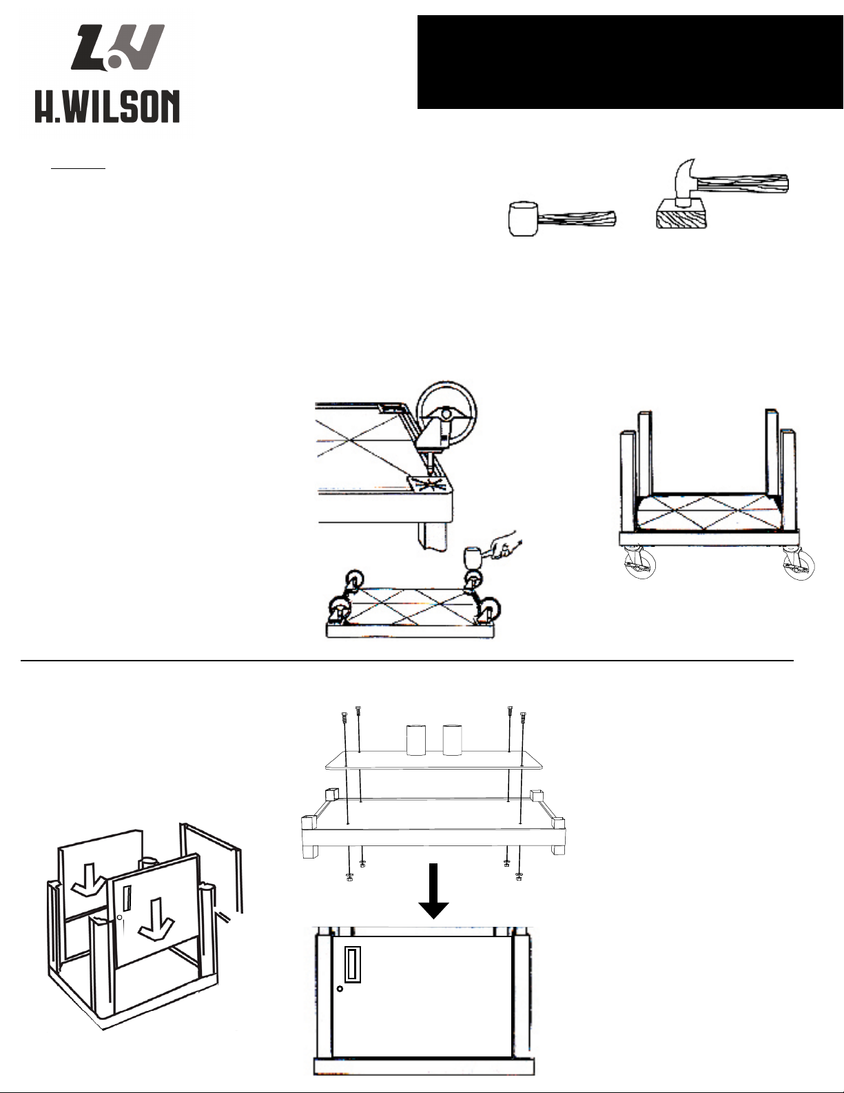
1. Insert casters into caster sockets,
making sure that you have the two
1
locking casters in the caster sockets
on the 18" long side of the cart that
has the handle.
Required Tools
(not included)
Rubber Mallet
2. Turn shelf so casters are on the oor.Place
16½" uted legs onto leg bosses. Press t
2
as much as possible with hands. Seat rmly
with rubber mallet.
Optional: metal hammer with
block of wood to cushion impact.
D
C
Bottom Shelf
D
Step 3: Locate back panel and slide down
into grooves of the 2 back legs (same side as
3
electrical bracket on top shelf. Take the two
side panels, slide into place. Take front panel
and slide into place positioned so that the
lock will be on the left.
K
H
B
L
M
Step 4: Place middle shelf (B) leg
bosses into lower fluted legs and press
4
until leg bosses are all the way in (tap
gently with mallet if necessary.
Step 5: Place the base plate (H) onto
the middle shelf (B) (with the welded
5
tubes at the back of the cabinet). Open
cabinet doors. Secure base to shelf with
4 Bolts (K), Washers (L) and Nuts (M).
Step 6: Repeat fluted leg steps.
6
G
C
Page 2
N
Shown without
cabinet and legs
for clear view
B
R
J
A
F
H
R
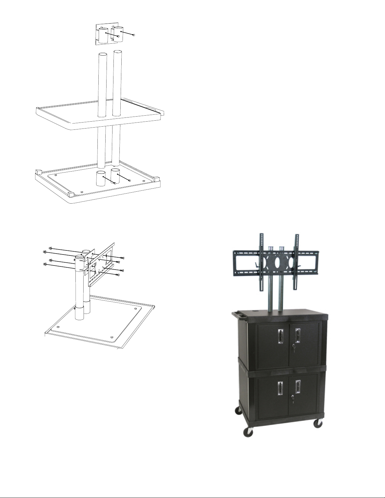
Step 7: Insert the two chrome tubes (J)into the welded cups on the
base (H). Secure with 2 Small bolts (R).
7
Step 8: Locate back panel and slide down into grooves of the 2 back
legs Take the two side panels, slide into place. Take front panel and
8
slide into place positioned so that the lock will be on the left.
Step 9: Line the holes in the Top Shelf (A) up with the chrome poles.
Lower top shelf until the bosses are in the fluted legs. Tap gently in
9
place. Lower inlay over poles onto the top shelf.
Step 10: Insert upper bracket (N) onto the chrome poles and secure in
place with two small bolts (R)
10
Q
P
Step11: Attach WFST mount (I) to upper bracket and secure in place
with Bolts, nuts and washers (O, P & Q)
11
TV Mounting Instructions are included with the WFST mount.
Electrical assembly mounting instructions are included with the
assembly.
I
O
 Loading...