

Page 1
www.luxorfurn.com
www.hwilson.com
WPSDD3 Instructions
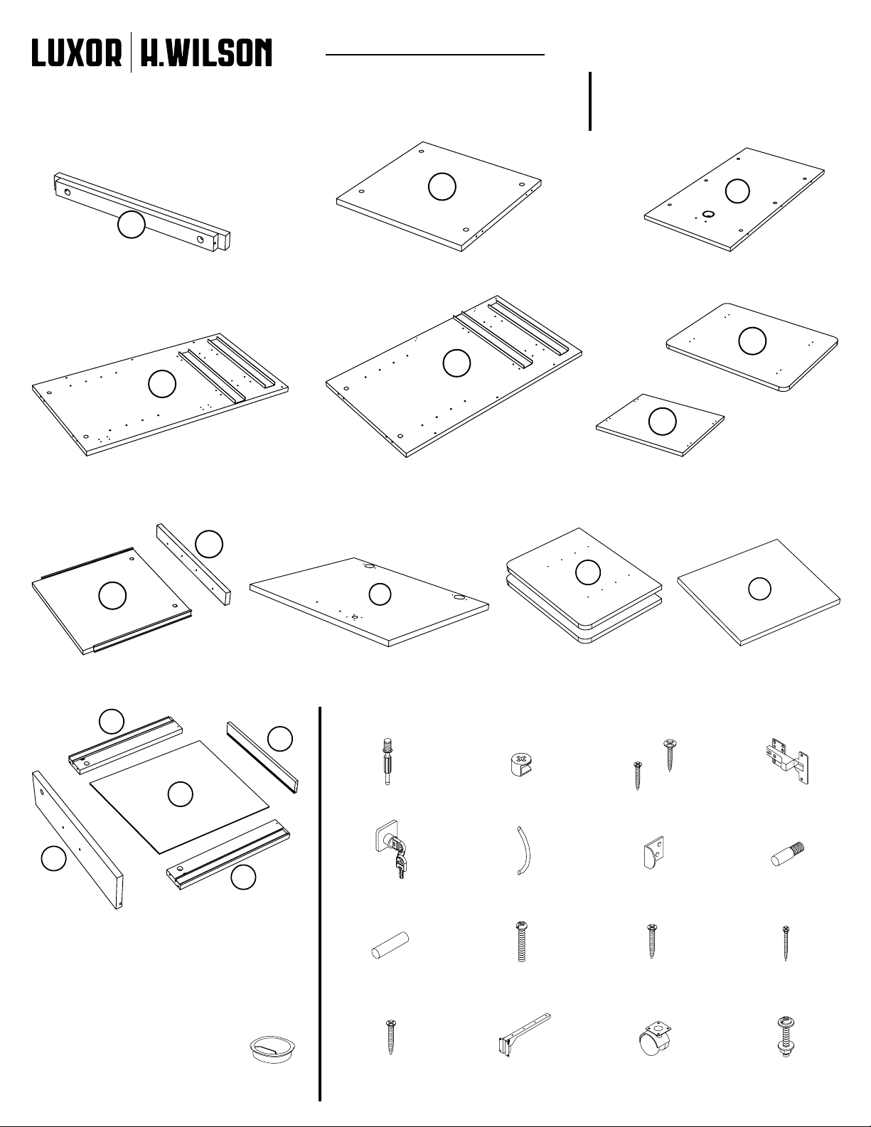
Parts List
04/05/13
1/5
Tools Required
- Phillips Screwdriver
- Drill + Phillips Drill Bit
2
1
1 - Top Support Brace x1 2 - Horizontal Divider Panel x1
5
4
4 - Right Side Panel x1
7b - Pullout Shelf
Front Panel x1
7b
7a
5 - Left Side Panel x1 6b - Bottom x1
8
3
3 - Back Panel x1
6a
6a - Top x1
6b
10
11
7a - Pullout Shelf Panel x1
9b
9e
9a
9a - Drawer Front Panel x1
9b - Left Drawer Side x1
9c - Right Drawer Side x1
9d - Drawer Back Panel x1
9e - Drawer Bottom x1
Box A - 1, 2, 3, 4, 5, 7a, 10
Box B - All Other Parts
9c
9d
8 - Door Panel x1
Hardware Pack
A Metal Dowel x30
E Lock Pack x2
I Wood Dowel x12
M Lock Screw x8P Grommet x1
Cb Caster Screw x16
B Cam x30
F Handle x3
J Handle Screw x6
N Side Shelf Bracket x4
Ca Wood Screw x30
G Lock Catch x2
K Drawer Back
Screw x4
O Casters x4
11 - Shelf x110 - Pull-up Side Panels x2
D Door Hinge x2
H Shelf Pin x4
L Lock Catch
Screw x4
T Side Bracket
Hardware x16
Page 2
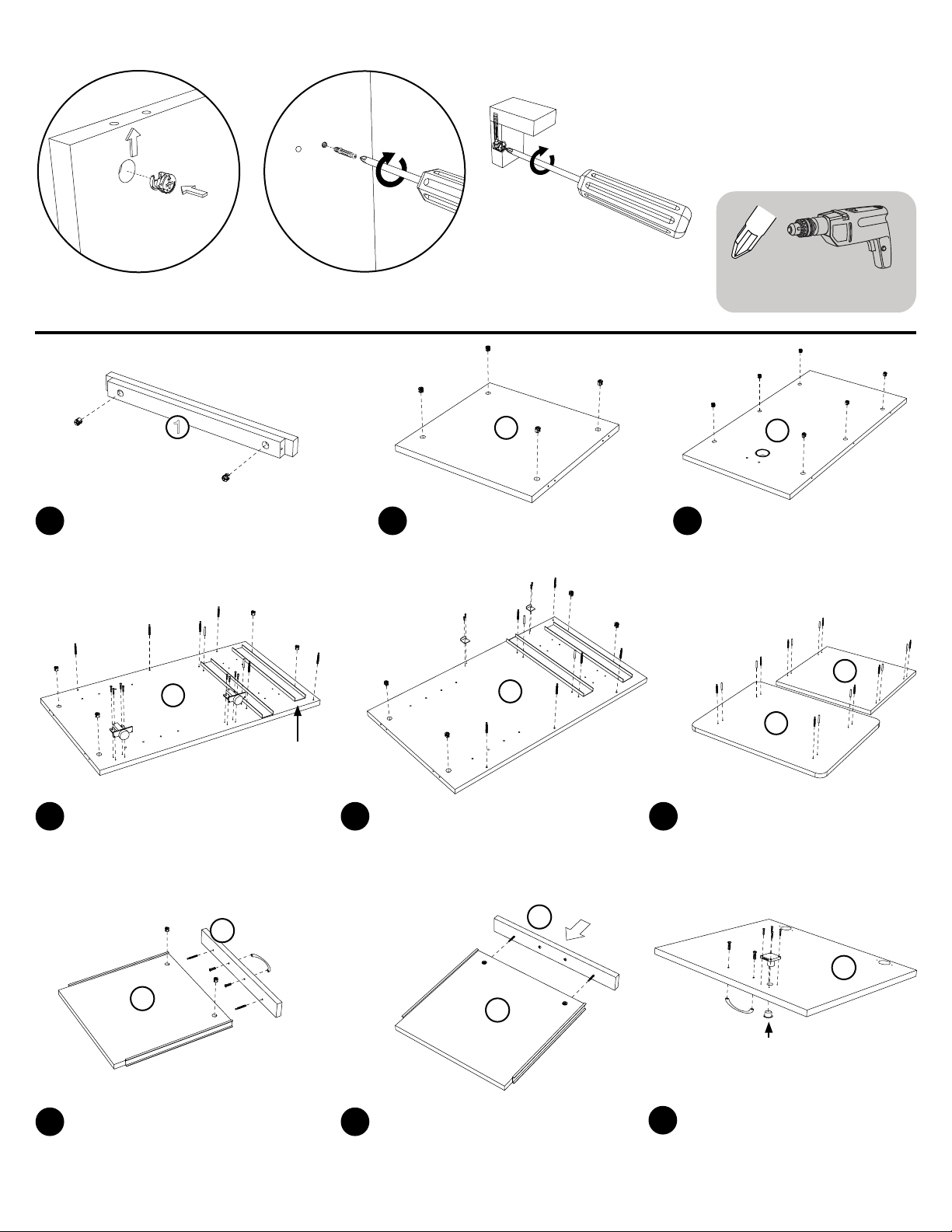
Proper Cam Installation:
1 2 3
Phillips
Screwdriver
A
B
The small arrow on the cam
faces toward the outside edge
Screw the metal dowel into
the threaded hole
90°
Phillips
Screwdriver
After panels are placed
together, turn the cam 90°
clockwise to lock in place
04/05/13
2/5
WARNING: Please follow
the cautionary guidelines
included with your drill.
Phillips Head Drill Bit
B
Insert 2 cams B into the top
1
support brace 1
A
B
Cax4
1
A
Cax4
4
B
D
B
A
A
I
I
D
Metal runners need to be
loosened to install cams
Upper cams may
B
come preinstalled
B
A
A
B
B
2
Insert 4 cams B into the
2
horizontal divider panel 2
Lx2
G
B
B
A
A
5
Lx2
B
B
B
3
A
B
G
I
I
A
B
A
A
B
B
B
3
Insert 6 cams B into the
back panel 3.
A
I
A
I
A
I
I
A
6a
A
B
B
A
I
A
6b
I
I
I
A
Insert 4 cams B, 6 metal dowels
4
A, 2 wood dowels I into the right
side panel 4. Use drill on 2 door
hinges D with 8 wood screws Ca.
B
7a
Install the metal dowels A in the
7a 7b
pullout shelf front 7b and 2 cams
B into the pullout shelf 7a. Install
the handle F onto the pullout shelf
front 7b, with the handle screws J.
7b
A
B
Jx2
F
A
5 6
Insert 4 cams B, 6 metal dowels A,
2 wood dowels I into the left side
panel 5. Use drill on 2 lock catches
G with 4 lock catch screws L.
7b
7a
Push the pull out shelf front panel
7b on to the pull out shelf 7a, and
turn the cams to lock into place.
The handle screws J should still
be visible.
Insert 4 metal dowels A and 4
wood dowels I into the top panel
6a. Repeat for bottom panel 6b.
Mx4
Jx2
F
Use drill on lock E with 4
8
lock screws M. Screw the
handle F onto the door panel
8 with 2 handle screws J.
E
8
Detach lock E faceplate
prior to installation
Page 3

Detach lock E
faceplate prior
to installation
E
Mx4
Ax2
Bx2
9b
Cam may come preinstalled. If not
loosen drawer runner to install cam.
9b
04/05/13
9d
K
9e
3/5
Jx2
Cax4
N
9a
Ax2
Cax4
Cax4
N
F
Screw 4 metal dowels A into drawer front 9a. Use
9a
drill on lock E with 4 lock screws M onto drawer front
9a. Install 4 cams into drawer sides 9b & 9c. Screw
handle F onto the drawer front 9a with handle screw J.
Bx2
N
10
9c
Cax4
N
10
K
9c
9a
Attach the drawer sides 9b & 9c to the drawer front
9b
9a, and turn the cams to lock into place. Slide the
bottom panel 9e down the grooves and then use drill
on drawer back 9d with 2 drawer screws K
(through the upper holes of 9b & 9c).
1
2
NOTE: Keep drawer
runner loosened in order
to tighten cam locks
P
3
Make sure the
grommet P of
back panel 3 is
below divider 2
4 or 5
Use drill on 2 side shelf brackets N into
10
side shelf 10 with 8 wood screws Ca.
Place the top support brace 1 the horizontal divider 2
11
and the back panel 3 onto a side panel 4 or 5. Tighten
the 6 cams that cover the metal dowels. Insert the
grommet P into back panel 3.
6a
4 or 5
Install the other side panel 4 or
12 13 14
5 onto the main unit. Tighten the
cams that cover the metal dowels.
With assistance, lift the unit so the
top is facing up. Install top panel
6a and tighten the 4 cams.
6b
With assistance lift the unit so the
bottom is facing up. Install the
bottom panel 6b and tighten the 4
cams.
Page 4

Cbx4
O
Cbx4
O
Cbx4
O
Cbx4
O
10
04/05/13
10
x8
T
Nuts go inside
of the unit
Tx8
4/5
Use drill on 4 casters O with the 16
15 16
caster screws Cb onto the bottom
panel 6b. Lock the 4 casters.
Cax2
8
Cax2
With assistance use drill on door 8 to
17 18
the main unit with 4 wood screws Ca.
With assistance lift the unit so the top is
facing up. With assistance install the side
shelves 10 with 16 bolts and nuts T.
Hx4
11
Install 4 shelf pins H at your desired height.
Install shelf 11 on the top of the shelf pins.
7
Install the assembled pullout shelf 7. The short lip
19 20
on the front of the shelf should face up. The shelf
will click when attached to the drawer runner.
9
Install the assembled drawer 9. The shelf will click
when it is attached to the inside drawer runners.
Page 5

Rubber Bumper
Drawer Slide Locations
Top Slide: Second hole from Bumper
Top Slide: Third hole from Bumper
Adjustment Sheet
04/05/13
5/5
To adjust the spacing between the top drawer and
pull-out shelf, loosen the front screw A and adjust
either up or down. Tighten the screw.
To adjust the door front to back, loosen the back
screw B, and move the door in or out. To adjust the
door left to right, loosen or tighten the front screw C.
A
B C
 Loading...