

Page 1
WPS6 Instruction Sheet
Do not completly tighten screws until step 5
H. Wilson Company
Address: 2245 Delany Rd.
Waukegan, IL
Phone: 800.245.7224
Fax: 800.245.8224
Email: sales@hwilson.com
web: www.hwilson.com
APRIL 2010 - REV00
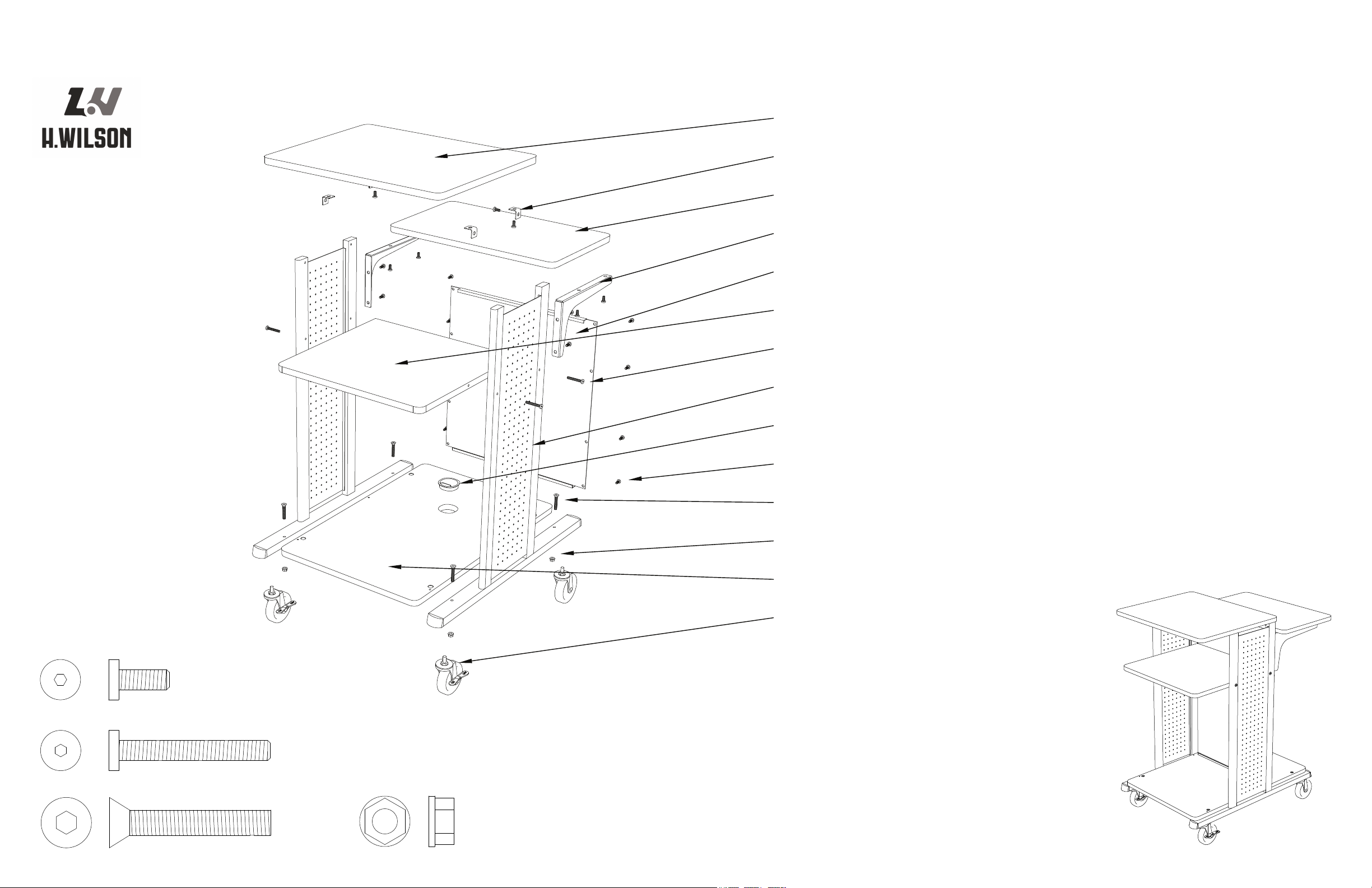
= J
= G
= K
= L
M. 1 - Bottom panel (20 3/8" x 30 5/8")
F. 1 - Middle shelf (20 3/8" x 19 1/4")
C. 1 Adjustable shelf (23 5/8" x 13 7/8")
A. 1 - Top (23 5/8" x 19 1/4")
I. 1 - Cable grommet pack
O. 1 - Small M6 Allen wrench
N. 4 - Casters (2 w/ Brake, 2 w/o Brake, Wrench)
L. 4 - M10 nuts
K. 4 - M10 x 35 Allen screws
J. 24 - M6 x 10 Allen panhead screws
H. 2 - Legs (Left & Right pair)
G. 4 - M6 x 35 Allen panhead screws
E. 1 - Metal back panel
D. 2 - Adjustable shelf brackets (Left & Right pair)
B. 4 - Small L brackets
P. 1 - Large M10 Allen wrench
Q. 4 - Small grommets
R. Stickers
Page 2
WPS6 Instruction Sheet
Do not completely tighten screws until step 5
H. Wilson Company
Address: 2245 Delany Rd.
Waukegan, IL
Phone: 800.245.7224
Fax: 800.245.8224
Email: sales@hwilson.com
web: www.hwilson.com
APRIL 2010 - REV00
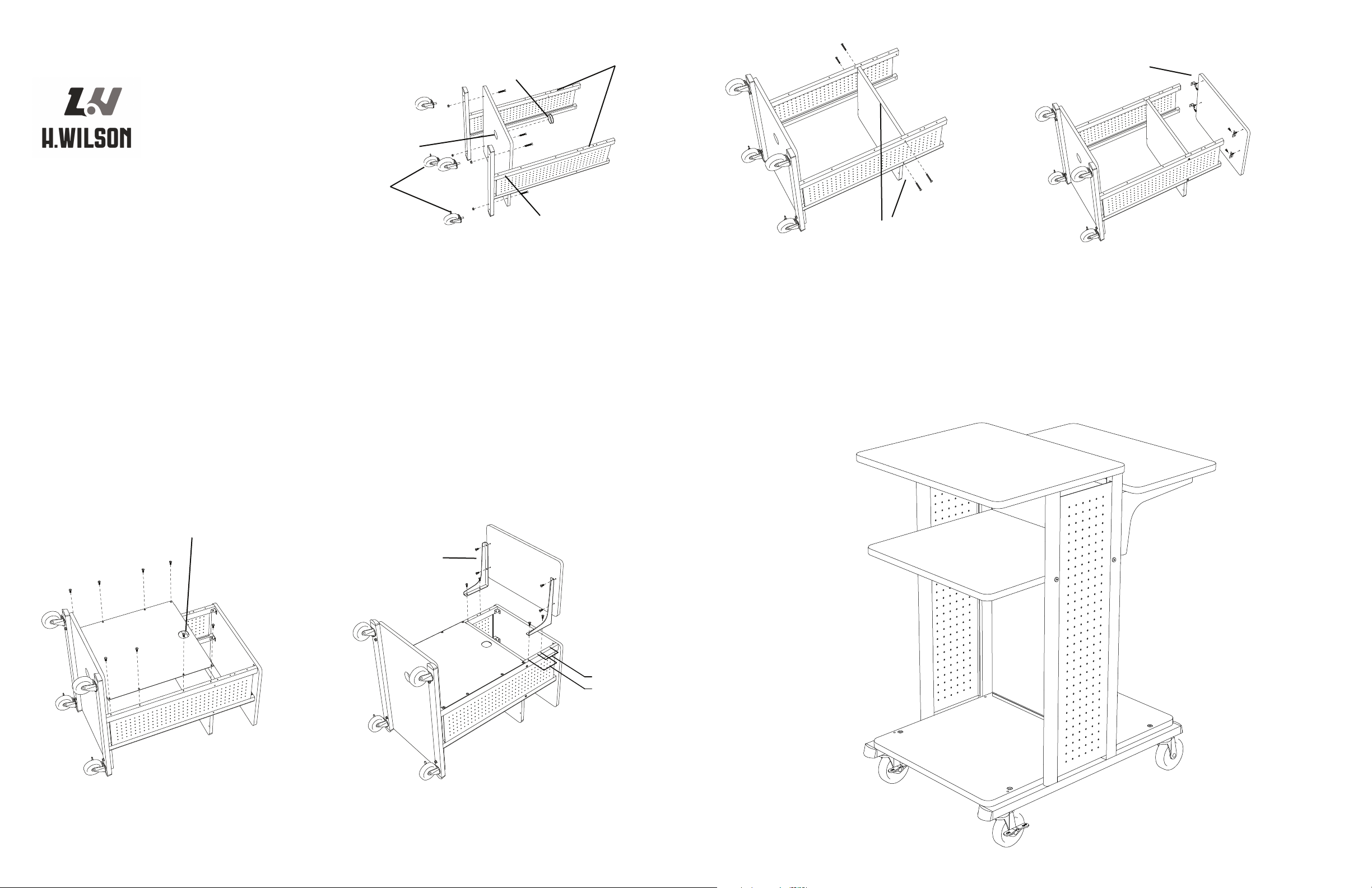
Step 1: Using the large Allen wrench(P), install the base panel(M.)
to the legs(H) with 4 - M10x35 Allen screws(K) and nuts(L).
Install the Casters(N) and tighten with the caster wrench. Install
the cable grommet(I), and cover remaining holes with the small
grommets(Q) and sticker(R).
Casters w/ brake
towards the front
Holes face up
Flush side of leg
faces out
Grommet hole
Cable grommet
Step 2: Using the small Allen wrench(O),
install the middle shelf(F) with 4 - M6x35
Allen screws(G).
Straight back and
rounded front corners
Step 3: Using the small Allen wrench,
install the top(A) to the legs with 4 - small L brackets(B)
and 8 - M6x10 Allen screws(J).
Attach brackets to
top panel rst
Step 4: Using the small Allen wrench,
install the back panel(E) to the legs with 8 - M6x10
Allen screws(J).
Cable pass-through
Position 1
Position 2
Step 5: Using the small Allen wrench,
install the adjustable shelf(C) to the
brackets(D) and legs with 8 - M6x10 Allen screws(J). Tighten all screws down.
Attach brackets to
adjustable shelf rst
Page 3

WPS6C Instruction Sheet
Do not completely tighten screws until step 5
H. Wilson Company
Address: 2245 Delany Rd.
Waukegan, IL
Phone: 800.245.7224
Fax: 800.245.8224
Email: sales@hwilson.com
web: www.hwilson.com
APRIL 2010 - REV00
= E
= I
= O
= P
M. 1 - Door panel (19 1/4" x 23 1/8")
F. 1 - Middle shelf (20 3/8" x 19 1/4")
C. 1 Adjustable shelf (23 5/8" x 13 7/8")
A. 1 - Top (23 5/8" x 19 1/4")
I. 4 - M6x35 Allen panhead screws
O. 4 - M10x35 Allen screws
N. 1 - Bottom panel (20 3/8" x 30 5/8")
K. 1 - Cable grommet pack
J. 1 - Left cabinet panel (18 3/16" x 23 1/4")
H. 1 - Metal back panel
G. 2 - Legs (Left & Right pair)
E. 24 - M6x10 Allen panhead screws
D. 2 - Adjustable shelf brackets (Left & Right pair)
B. 4 - Small L brackets
P. 4 - M10 nuts
Q. 4 - Casters
(2 w/ Brake, 2 w/o Brake, Wrench)
S. 2 - Spindles
R. 1 - Magnetic catch and metal strip
T. 1 - Cam lock and key
V. 2 - Handle screws
U. 1 - Handle
W. 6 - 1/2" wood screws
L. 1 - Right cabinet panel (17 7/16" x 23 1/4")
Tools:
W. 1 - Small M6 Allen wrench
X. 1 - Large M10 Allen wrench
Tool Required
1 - Phillips screw driver
= V
= W
Page 4

WPS6C Instruction Sheet
Do not completely tighten screws until step 5
H. Wilson Company
Address: 2245 Delany Rd.
Waukegan, IL
Phone: 800.245.7224
Fax: 800.245.8224
Email: sales@hwilson.com
web: www.hwilson.com
APRIL 2010 - REV00
Step 1: Using the large Allen wrench(X), install the base panel(N)
to the legs(G) with 4 - M10x35 screws(O) and nuts(P).
Install the Casters(Q) and tighten with the caster wrench.
Install the cable grommet(K).
Step 1: Using a Phillips screw driver, install the magnetic catch(R) to the middle
shelf(F) with 2 - 1/2” wood screws(W). Install the metal strip(R) and cam lock(T)
with 4 - 1/2” wood screws to the door panel(M). Install the handle(U) with
the handle screws(V) to the door. Install the spindles(S) to the door.
Casters w/ brake
towards the front
Holes face up
Flush side of leg
faces out
Grommet hole
Cable grommet
Step 2: Using the small Allen wrench,
install the metal back panel(H) with the 8 - M6x10
Allen screws(E).
Step 3: Using the small Allen wrench,
install the top(A) to the legs with 4 - small L brackets(B)
and 8 - M6x10 Allen screws(E).
Attach brackets to
top panel rst
Step 4: Install the left cabinet(J), right cabinet(L)
and door(M) panels. Using the small Allen wrench, install
the middle shelf(F) with 4 - M6x35 Allen screws(I).
Cable pass-through
Position 1
Position 2
Step 5: Using the small Allen wrench,
install the adjustable shelf(C) to the
brackets(D) and legs with 8 - M6x10 Allen screws(E). Tighten all screws.
Attach brackets to
adjustable shelf rst
Left panel slot faces up
Middle Shelf
Door Panel
 Loading...