

Page 1
WFST Installation Instructions
37”-63” Universal Flat Panel Display Tilted Wall Mount
11/6/13
THE WARRANTY W
ILL ONLY BE VALID IF YOU FOLLOW THE INSTRUCTIONS CAREFULLY.
Please do not begin installation until you have thoroughly read and understood these instructions.
Improper installation may cause serious injury and/or damage. It is recommended thata qualified
contractor install the WFST Universal Tilted Wall Mount.
Make sure that the wall you plan to use will safely support four times the combined weight of the
mounted equipment, including its accessories.
The WFST Universal Tilted Wall Mount supports LCD and Plasma Flat Panel Displays
from 37 to and supportsamaximum load of kg lbs
This products suits displays with 800mmx500mm(32 x20 mounting hole patterns
" "
" "
A second person will be required to assist with several st
0028.0936
( ).
eps.
.)
The manufacturer does not accept responsibility for incorrect installation.
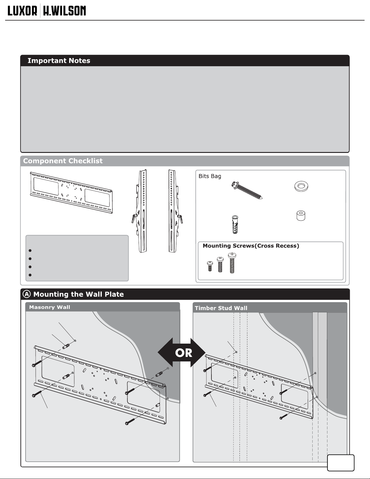
Metal washer (x4)Ø6
Spacer (x4)
Wall Plate(x1)
Lag Bolt
8*70mm(x4)
Anchor(x4)
TOOLS REQUIRED:
Power Drill
1/4”
or 1/2” Drill Bit
Phillips Head Screw Driver
Spirit Level
Left Hook
Bracket(x1)
Right Hook
Bracket(x1)
M5x16 mm (x4 each)
M6x16 mm (x4 each)
M8x35mm (x4 each)
13mm(½”)
Hole
Wall Anchor
Lag bolt
8x70mm
IMPORTANT:
Tighten lag bolts s o that wall plate is rmly attached to wall,
but DO NOT over tighten. The lag bolts can b e damaged b y
over tightening which will strip their threading.
Final tightening oag bolts should be done b y hand using
a ratchet wrench and socket.
TIP:
Useaspirit level to
ensure the wall p late
is horizontal.
6mm(1/4”)
Hole
Lag bolt
8x70mm
TIP:
Use a spirit level to
ensure the wall plate
is horizontal.
Timber Stud
1 / 2
Page 2
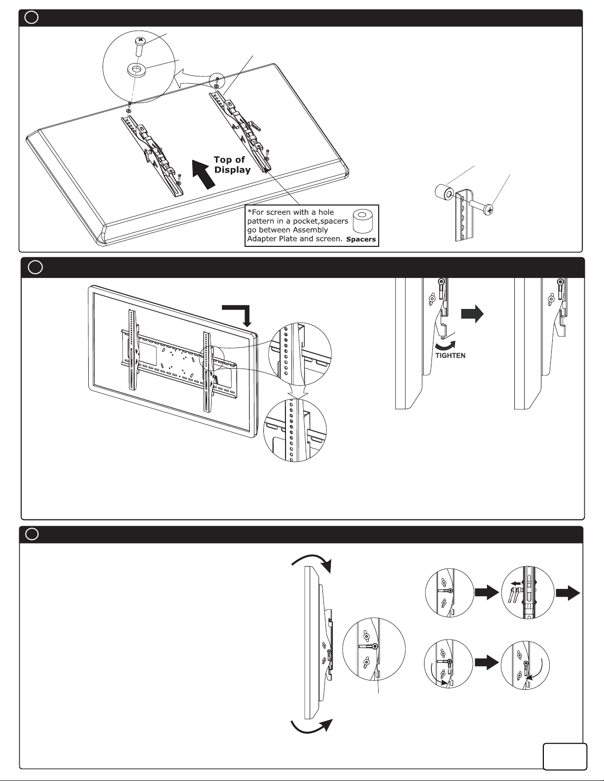
B
Attach the display
Mounting
screws
Metal washer
Ø6
Hook Bracket
Fixed the hook bracket onto the display with
the selected mounting screws, square washers,
and any required spacers.
Tighten them using Philips head screw driver
Note:
Recessed Mounting Holes. If the mounting holes are
recessed into the back of the display, use the supplied
spacers to pack the recessed hole. Ensure that the
hook brackets are securely fixed to the display.
C
Attaching the display to the wall plate
c
Step 1
Note:
This procedure will require two persons.
Step 1: Lift the display
Lift the display onto the wall plate a s shown(Fig.1.).
Step 2: Lock the display
Tighten the Philips head screw M5x35 until attach the wall plate as shown(Fig.2.).
Note:
For demonstration purposes, the wall has been omitted from the above images.
Fig.1.
Spacer
Philips head screw
M5x35
Mounting screws
Fig.2.
Step 2
D
Adjusting the display
Tilt Adjustment -Raising o r lowering the screen
to improve viewing angle.
Grasp the upper and lower edges of the display,
and then turn it to the desired tilt angle(Fig.3.).
To lock the tilt angle, tighten the tilt knob(Fig.4.) securely.
Note: For heavier displays, never fully release the tilt knob
without fully supporting the display.
The tilt lever includesaratchet function, so that it can be
lifted and repositioned for next turn. To operate the ratchet,
pull the lever and then turn it in the desired direction. Repeat
as necessary until the tilt tension is set properly(Fig.5.).
Installation complete!
Now, you can enjoy your display!
Tilt 15
Fig.3.
Tilt -5
Fig.4.
Turn
A
C
B
Tighten
D
Fig.5.
2 / 2
 Loading...