

Luxor|H.Wilson WFLCDM User Manual
H. Wilson Company
PO Box 290
Waukegan, IL 60079
Phone: 800-245-7224
Fax: 800-245-8224
www.hwilson.com
sales@hwilson.com
Parts for WFLCDM
(1) ceiling mounting bracket (4) plastic spacers
(1) two-part mounting assembly (4) arms
1
(1) 6
⁄4" threaded pipe (4) 6mm nuts
(4) 6mm shoulder screws (6) M6 hex head screws
(8) 6mm washers
(4) 3" screws + (4) washers
Instructions:
1. Secure ceiling mount to ceiling using (4) 3" screws and
washers. Place washer on the outside of hole of mounting
bracket, then screw in the 3" screw. See Diagram A.
NOTE: Do NOT attach to a drop ceiling.
WFLCDM
Universal Fixed Height LCD
Projector Mount
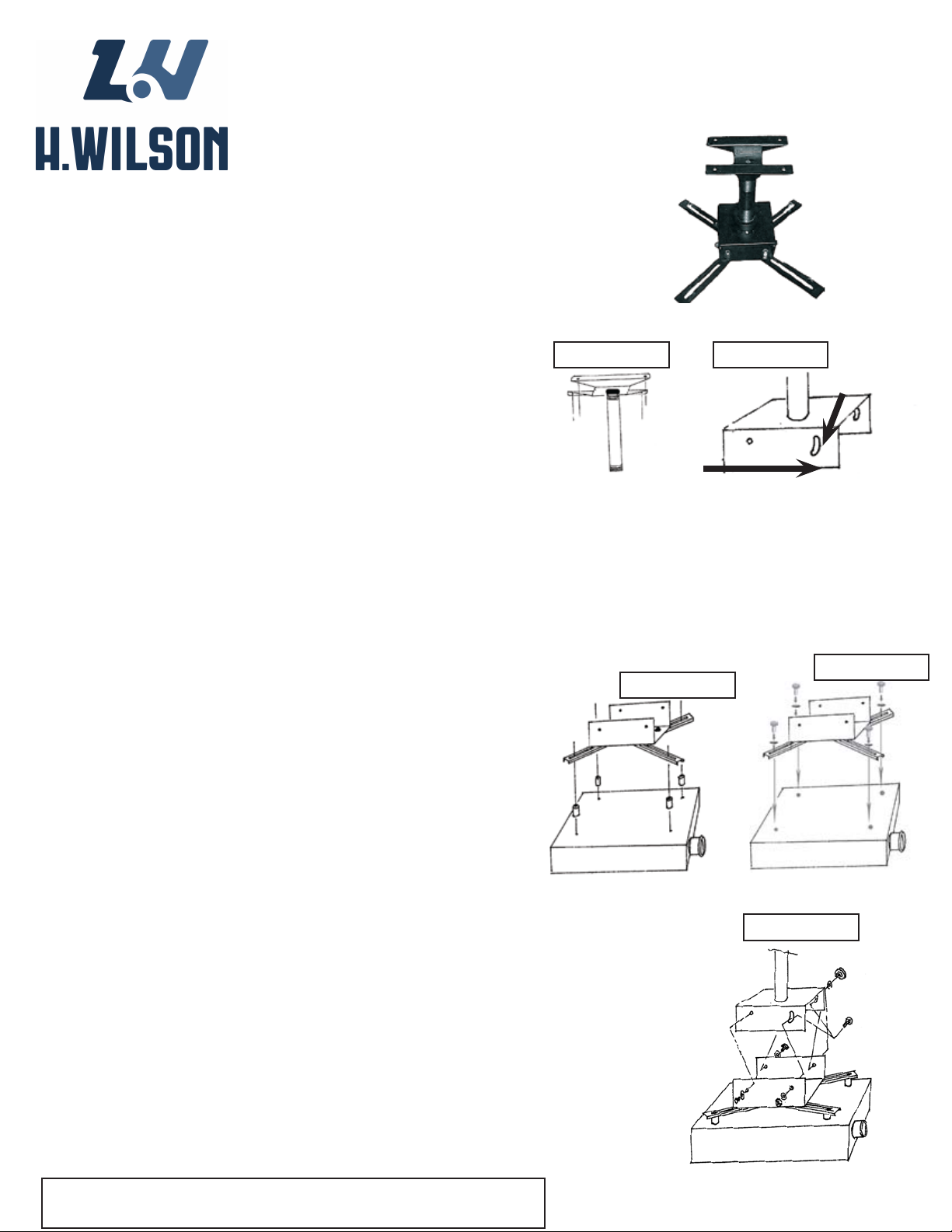
Diagram A
Diagram B
Slot A
2. Attach the 6" threaded pipe by screwing into the mounted
ceiling bracket. See Diagram A.
3. Attach one part of the mounting assembly to the 6"
threaded pipe by screwing it onto pipe, making sure the
larger slotted holes are facing in the direction the projector
will be facing. See Diagram B.
4. Attach (4) arms to other part of mounting bracket
using (4) 6mm shoulder screws & nuts. Do NOT tighten.
Determine correct position of arms for projector location
and then tighten the (4) nuts. See Diagram C.
5. Connect projector to arms and bracket assembly using screws
that are recommended by your installer. Align arm and bracket
assembly over the female fittings on your projector. Place nut
over female fitting on top of arm. Thread screw through the nut
and into the female fitting on the projector. When screw is in
palce securely, tighten nut. Do not over tighten. OPTIONAL: We
have provided (4) spacers to prevent marring of LCD surface; to
create ventilation where necessary, and to allow level attachment
of projector if necessary. See Diagram C or D.
6. Take projector and bracket & arm assembly and attach
to mounted pipe assembly by using (4) M6 hexhead screws
and washers. Insert the bolt and washer on the outside of
the bracket and tighten into the welded nut on the inside of
the bracket. Diagram E.
LCD Projector will face
in this direction. Note
placement of slotted
holes.
Diagram D
Diagram C
Diagram E
OPTIONAL: For tilting position loosen the (2) bolts in Slot
A (See Diagram B) located on side of mounting bracket.
Adjust for preferred tilt. Level or up to 10 degree tilt. Tighten
bolts when tilt is correct.
8. TO secure the ceiling mounting bracket and mounting
assembly, use (2) M6 hexhead screws.
Please have a professional install this H. Wilson Product.
 Loading...