

Page 1
H. Wilson Company
PO Box 290
Waukegan, IL 60079
Phone: 800-245-7224
Fax: 800-245-8224
www.hwilson.com
sales@hwilson.com
Parts for WCALCDM
(1) 1 1/4" - 25" long inner adjustable pipe
(1) 1 1/2" - 23 1/2" long outer adjustable pipe, attached to mounting bracket
(1) ceiling mounting bracket
(4) arms
(1) mounting assembly (4) plastic spacers
(5) M6 hexhead screws (12) 6mm nuts
(16) 6mm washers (12) 6mm shoulder screws
(1) M10 screw (1) 10mm nut
(2) 10mm washers (4) 3" screws & (4) washers
(4) L brackets, no slots (4) slotted L brackets
Instructions:
1. Secure ceiling bracket to ceiling using (4) 3" screws and washers. Place
washer on the outside of hole of mounting bracket, then screw in the 3"
screws. Diagram A.
WCALCDM
Universal Adjustable
Height LCD
Projector Mount
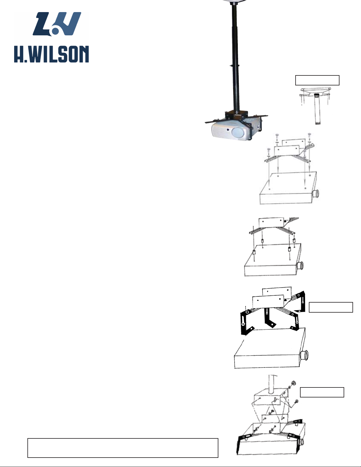
Diagram A
Diagram B
NOTE: Do NOT attach to a drop ceiling.
2. Secure 1 1/2" - 15" long inner adjustable pipe to ceiling mount by screwing
it in. See Diagram A.
3. Attach (4) arms to mounting assembly using 6mm shoulder screws. Do
not tighten. Determine correct position of arms for projector location and then
tighten the (4) nuts. See Diagram B
4. Take one slotted L bracket and attach to top of slotted arm bracket using (1)
6mm shoulder screw, nut and 6mm washer. Then take unslotted L bracket and
attach to outside of slotted L bracket using (1) 6mm shoulder screw, nut and
6mm washer. Continue doing this to all four arms. Diagram D
5. Attach this assembly to other part of mounting bracket using M6 hexhead
screws. Do NOT tighten. Determine correct position of arms for projector location and then tighten the (4) nuts. Diagram D.
6. Connect projector to arms and bracket assembly using screws that are recommended by your installer. Align arm and bracket assembly over the female
fittings on your projector. Place nut over female fitting on top of arm. Thread
screw through the nut and into the female fitting on the projector. When screw
is in palce securely, tighten nut. Do not over tighten. OPTIONAL: We have
provided (4) spacers to prevent marring of LCD surface; to create ventilation
where necessary, and to allow level attachment of projector if necessary. See
Diagram B or C.
Diagram C
Diagram D
7. Take projector and bracket & arm assembly which is attached to the outer
23 1/2" long pipe and slide outer pipe over mounted inner pipe assembly and
secure to your desired length. Insert the bolt and washer on the outside of the
bracket and tighten into the welded nut on the inside of the bracket. Diagram E.
OPTIONAL: For tilting position loosen the (2) bolts in Slot A located on side of
mounting bracket. Adjust for preferred tilt. Level or up to 10 degree tilt. Tighten
bolts when tilt is correct.
8. To secure to the ceiling mounting bracket, use (1) M6 hexhead screw.
Please have a professional install this H. Wilson Product.
Diagram E
 Loading...