

Page 1
Instruction Sheet
Endura Overhead Projector Tables
Models OHT42, OHT42PS, and OHS42
Customer Service Dept
2245 Delany Rd • Waukegan, IL 60087
Ph: 847/244-1800 • 800/323-4656
Fax: 847/244-1818 • 800/327-1698
OHT42
OHT42PS
OHS42
Parts List
OHT42
1 - Top shelf w/handle
1 - Middle shelf w/8 leg posts
1 - Bottom shelf w/caster sockets
1 - Set short legs
1 - Set long legs
4 - Casters (2 w/brake)
1 - Electric assembly
Tools Required:
Rubber mallet
OHS42
1 - Top shelf w/utility tray
1 - Middle shelf w/8 leg posts
1 - Bottom shelf w/caster sockets
1 - Set short legs
1 - Set long legs
4 - Casters (2 w/brake)
1 - Electric assembly
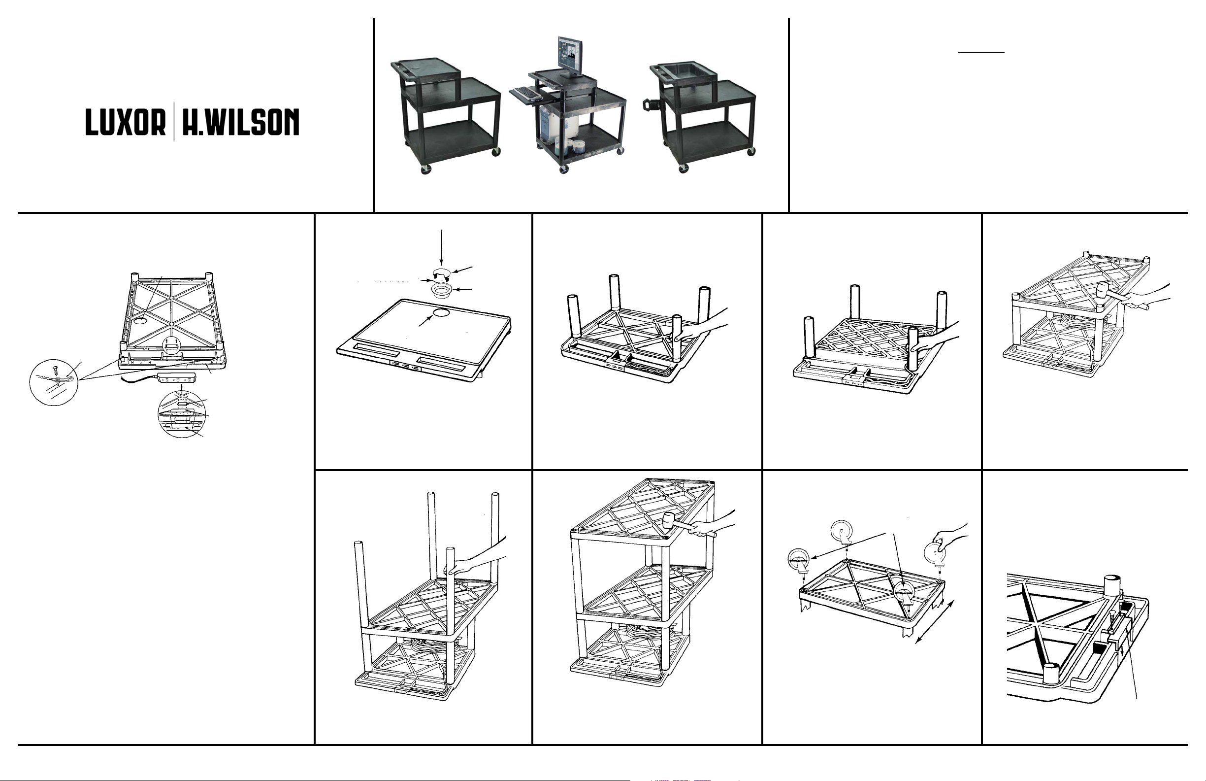
Illustration A
1. The electric unit should be
assembled first. Cord wrap must be
installed on leg before assembly of
complete unit. See below.
CORD
MANAGEMENT
TIE
2.Secure power cord plug
management ties into starter holes
with sheet metal screws.
OHT42/OHS42 ONLY
CABLE GROMMET HOLE
3 PLUG UNIT
3. Firmly seat electric assembly 3 plug
unit into handle plug housing as
illustrated. Secure with power cord plug
retaining bracket.
CORD RETAINING TRACK
POWER CORD PLUG
RETAINING BRACKET
3 PLUG UNIT
PLUG HOUSING
Model OHT42
1.
Install grommet ring by tapping into place with rubber
mallet. Insert grommet cap as illustrated. For tables
with electric assembly, snap off cord guide cover from
grommet cap so equipment plug may be run through
grommet plug unit, then insert grommet cap into
grommet ring.
Both Models
Model OHT42 Model OHS42 Both Models
4.
Position second shelf (with 8 leg posts) ribbed side up,
over the 4 legs and insert leg posts into legs. Using a
2.
Lay top shelf (with handle) ribbed side up on a smooth
surface. Push all 4 short legs onto leg posts.
Both Models
3.
Lay top utility shelf (with handle) ribbed side up on a
smooth surface. Push all 4 short legs onto leg posts.
Both Models
PLACE LOCKING CASTERS
AS ILLUSTRATED
rubber mallet, firmly hammer bottom shelf into legs
until all four legs are seated (flush) against the surfaces
of both shelves.
If your Endura Overhead Projector
Table does not have the Electrical
Assembly and Cable-Track
Management System, start by
closing the electric plug housing
in the handle of the top shelf as
illustrated.
TM
Cord
5.
Push set of 4 long legs into leg posts of second shelf
and firmly hammer until properly seated.
6.
Position bottom shelf, ribbed side up, over the 4 long legs
and insert leg posts into legs. Using a rubber mallet, firmly
hammer bottom shelf into legs until all four legs are seated
(flush) against the surfaces of both shelves.
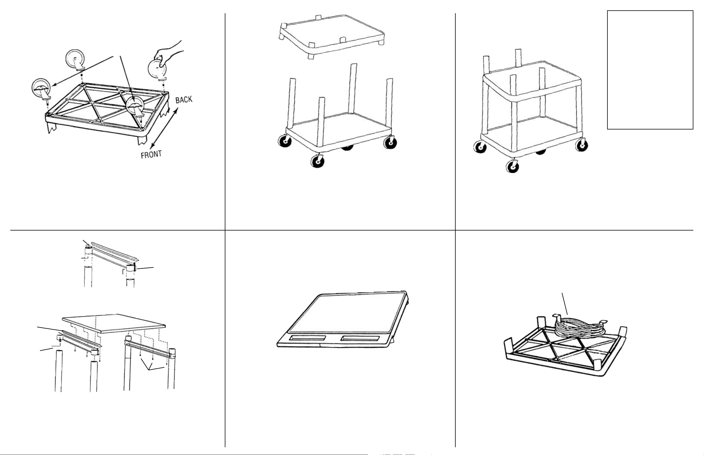
BACK
FRONT
7.
Push the four casters firmly into the holes in each
corner of the bottom shelf. Important: casters must be
fully seated. Tap firmly with rubber mallet to properly
seat casters. Turn your table right side up. It is now
ready for use.
PLUG
HOUSING
COVER
Page 2
Model OHT42PS
Parts List
PLACE LOCKING CASTERS
AS ILLUSTRATED
1.
Push the four casters firmly into the holes in each corner of the bottom
shelf. Important: casters must be fully seated. Tap firmly with rubber
mallet to properly seat casters.
2.
Insert longer legs onto the leg post on the bottom shelf and firmly
hammer until properly seated. Then insert the leg post on the middle
shelf into the legs.
OHT42PS
1 - Top shelf w/handle
1 - Middle shelf w/8 leg posts
1 - Bottom shelf w/caster sockets
1 - Set short legs
1 - Set long legs
4 - Casters (2 w/brake)
1 - Electric assembly
1 - Cord wrap
1 - Keyboard
1 - Runner
Tools Required:
Rubber mallet
3.
Push smaller legs onto the leg post on the middle shelf.
SHELF RUNNER
ADAPTER
Allen head set
screw & wrench
TAB
Allen head set
screw & wrench
Set shelf height as
desired then tighten
Allen head set
screws to secure
Allen head set
screw & wrench
LOCKING TONGUE
SCREWS
4.
Slide runners onto the legs and tighten down to desired height. Align
holes on the shelf adapters to the holes on the bottom of the keyboard
and attach using six sheet metal screws. Slide the rear of the shelf
adapters under the tab on the back of the runners and snap the front of
the shelf adapters onto the back tongue on the front of runners.
5.
Insert the leg post on the top shelf into the smaller legs.
IMPORTANT: Electric Assembly should
be assembled first.
ELECTRIC ASSEMBLY
Align cord bracket to the pre-drilled holes on the underside
of the middle and attach using two silver screws.
Page 3

Instruction Sheet
Endura Overhead Projector Tables
Models OHT42PS, and OHT42PSC
Customer Service Dept
2245 Delany Rd • Waukegan, IL 60087
Ph: 847/244-1800 • 800/323-4656
Fax: 847/244-1818 • 800/327-1698
OHT42PS
Parts List
OHT42
1 - Top shelf w/handle
1 - Middle shelf w/8 leg posts
1 - Bottom shelf w/caster sockets
1 - Set short legs
1 - Set long legs
4 - Casters (2 w/brake)
1 - Electric assembly
Tools Required:
Rubber mallet
OHS42
1 - Top shelf w/utility tray
1 - Middle shelf w/8 leg posts
1 - Bottom shelf w/caster sockets
1 - Set short legs
1 - Set long legs
4 - Casters (2 w/brake)
1 - Electric assembly
Illustration A
1. The electric unit should be
assembled first. Cord wrap must be
installed on leg before assembly of
complete unit. See below.
CORD
MANAGEMENT
TIE
2.Secure power cord plug
management ties into starter holes
with sheet metal screws.
OHT42/OHS42 ONLY
CABLE GROMMET HOLE
3 PLUG UNIT
3. Firmly seat electric assembly 3 plug
unit into handle plug housing as
illustrated. Secure with power cord plug
retaining bracket.
CORD RETAINING TRACK
POWER CORD PLUG
RETAINING BRACKET
3 PLUG UNIT
PLUG HOUSING
Model OHT42
1.
Install grommet ring by tapping into place with rubber
mallet. Insert grommet cap as illustrated. For tables
with electric assembly
grommet cap so equipment plug may be run through
grommet plug unit, then insert grommet cap into
grommet ring.
, snap off cord guide cover from
Both Models
Model OHT42 Model OHS42 Both Models
4.
Position second shelf (with 8 leg posts) ribbed side up,
over the 4 legs and insert leg posts into legs. Using a
2.
Lay top shelf (with handle) ribbed side up on a smooth
sur
face. Push all 4 short legs onto leg posts.
Both Models
3.
Lay top utility shelf (with handle) ribbed side up on a
smooth sur
face. Push all 4 short legs onto leg posts.
Both Models
PLACE LOCKING CASTERS
AS ILLUSTRATED
rubber mallet, firmly hammer bottom shelf into legs
until all four legs are seated (flush) against the sur
of both shelves.
If your Endura Overhead Projector
Table does not have the Electrical
Assembly and Cable-Track
Management System, start by
closing the electric plug housing
in the handle of the top shelf as
illustrated.
TM
faces
Cord
Cabinet pack instructions
on back.
5.
Push set of 4 long legs into leg posts of second shelf
and firmly hammer until properly seated.
6.
Position bottom shelf, ribbed side up, over the 4 long legs
and insert leg posts into legs. Using a rubber mallet, firmly
hammer bottom shelf into legs until all four legs are seated
(flush) against the sur
faces of both shelves.
BACK
FRONT
7.
Push the four casters firmly into the holes in each
corner of the bottom shelf. Important: casters must be
fully seated. T
seat casters. Turn your table right side up. It is now
ready for use.
ap firmly with rubber mallet to properly
PLUG
HOUSING
COVER
Page 4

18” LEG
RUBBER BAND
BOTTOM
SHELF
LEG POST
2
With bottom shelf facing up push all four 18” legs
onto leg posts. Using rubber mallet hammer legs
firmly into position. Legs must be seated (flush)
against the shelf surface. Place rubber band
around legs to aid in the assembly of cabinet
side panels and doors.
SIDE
LEGS
PANEL
SIDE VIEW WITH
PANEL SEATED
INSIDE SHELF LIP
3
Install the side panels first. Slide panels down
between legs until they are nested inside the
shelf lip and flush against the shelf surface.
Rubber band will hold legs and side panels in
place while installing back panel and front door.
TOP VIEW
4
Install the back panel in the same manner as
shown in Step #3. NOTE: Cabling hole in back
panel should be toward the top.
5
Install door panel same as back panel, with
door handle at top.
CENTER
SHELF
6
Begin seating of center shelf by holding door panel,
leg and side panel as illustrated. Gently tap corner
post into leg. Repeat on all 4 sides until all posts
are partially inserted into legs. Now repeat hammering action more firmly going around to each
shelf post and driving the leg posts more securely
into the legs.
Top of panels and door frame must be nested into
the underside of the center shelf lip in the same
manner as the bottom shelf.
SHELF RUNNER
ADAPTER
Allen head set
screw & wrench
TAB
Allen head set
screw & wrench
Set shelf height as
desired then tighten
Allen head set
screws to secure
Allen head set
screw & wrench
LOCKING TONGUE
SCREWS
4.
Slide runners onto the legs and tighten down to desired height. Align
holes on the shelf adapters to the holes on the bottom of the keyboard
and attach using six sheet metal screws. Slide the rear of the shelf
adapters under the tab on the back of the runners and snap the front of
the shelf adapters onto the back tongue on the front of runners.
5.
Insert the leg post on the top shelf into the smaller legs.
IMPORTANT: Electric Assembly should
be assembled first.
ELECTRIC ASSEMBLY
Align cord bracket to the pre-drilled holes on the underside
of the middle and attach using two silver screws.
 Loading...