

Page 1
Instruction Sheet
Endura Models LEM32, LEM32T & LEM32TT
www.luxorfurn.com
www.hwilson.com
PARTS LIST
LEM32 LEM32T LEM32TT
x1 - 24x32 Top Shelf w/
Handle
x4 - 17.5˝ Legs
x1 - 24x32 Bottom Shelf w/
Cutout
x1 - Set of 4˝ Casters
2 w/ Locking Brake
x1 - Electric Assembly
x2 - Cable Clips
x1 - Grommet Cord Guide
x1 - 24x12 Terminal Platform
x4 - 8˝ Legs
x1 - 24x32 Middle Shelf w/
Handle
x4 - 17.5˝ Legs
x1 - 24x32 Bottom Shelf w/
Cutout
x1 - Set of 4˝ Casters
2 w/ Locking Brake
x1 - Electric Assembly
x2 - Cable Clips
x2 - Grommet Cord Guide
x1 - 24x12 Terminal Platform
x1 - 24x32 Middle Shelf w/
Handle
x8 - 20˝ Legs
x1 - 24x32 Bottom Shelf w/
Cutout
x1 - Set of 4˝ Casters
2 w/ Locking Brake
x1 - Electric Assembly
x2 - Cable Clips
x2 - Grommet Cord Guide
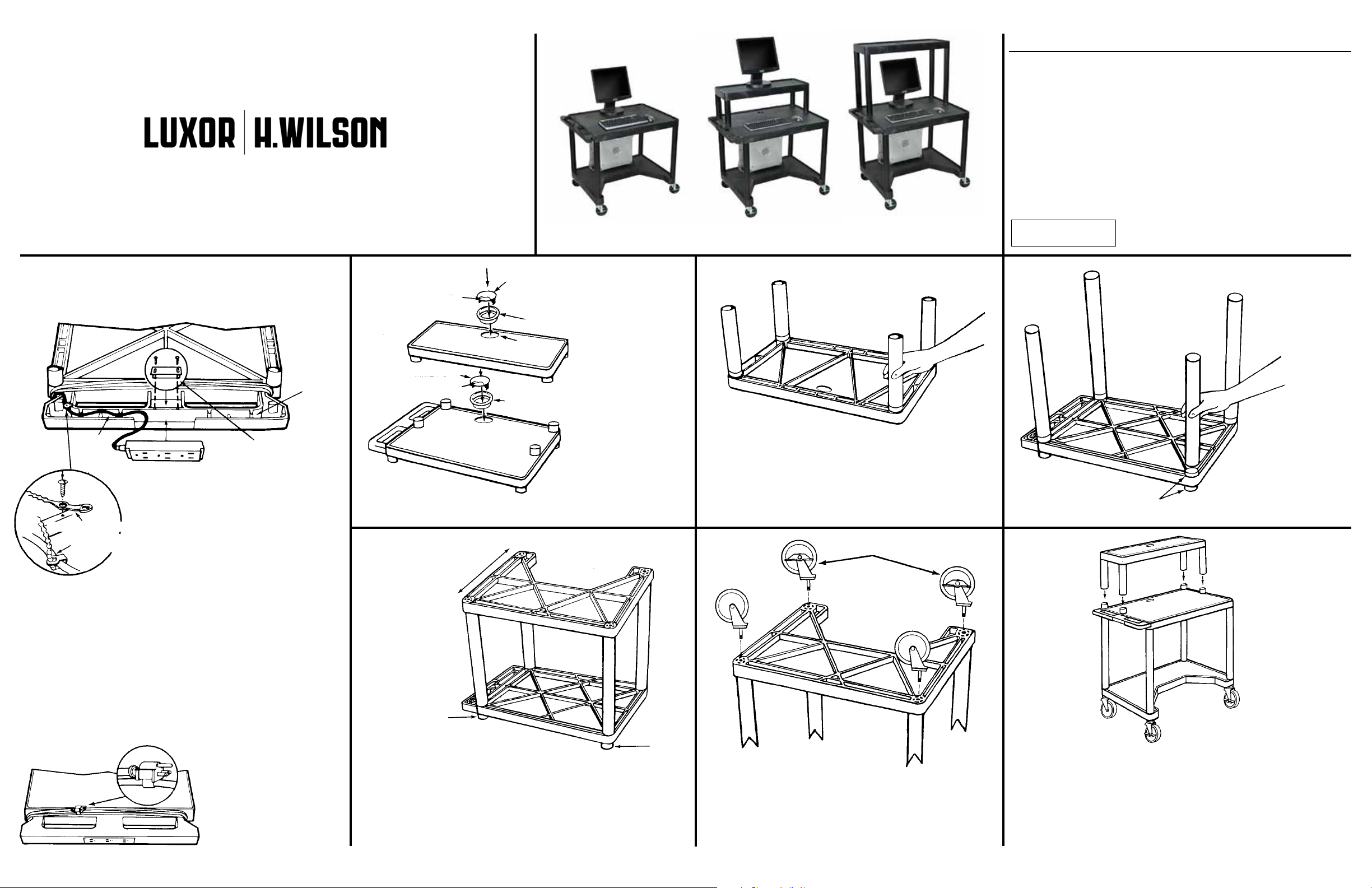
IMPORTANT
The electrical unit should
be assembled first.
CORD
RETAINING
TRACK #1
3 PLUG UNIT
A
CORD MANAGEMENT TIE
TIE IS IN SECURED
POSITION
POWER CORD PLUG
RETAINING BRACKET
CORD
RETAINING
TRACK #2
CORD GUIDE COVER
LEM32T / LEM32TT
TERMINAL
PLATFORM
GROMMET CAP
CORD GUIDE COVER
MIDDLE SHELF
GROMMET CAP
GROMMET
CABLE GROMMET HOLE
GROMMET RING
FRONT
LEM32 LEM32T LEM32TT
RING
1.
Install grommet
rings by tapping into
place with rubber
mallet. Snap off cord
guide cover from
grommet cap so
equipment plug may
be run through
grommet to plug
unit, then insert
grommet cap into
grommet ring.
2.
Lay terminal platform (long narrow shelf with grommet hole)
ribbed side up on a smooth surface. Push 1 set of short legs
onto leg posts. Set aside temporarily and continue with step
No. 3.
LOCKING CASTERS
For LEM32T &
LEM32TT
Tools Required:
Rubber Mallet
LEG POST
3.
Lay middle shelf
(with handle) ribbed
side up on a smooth
surface. Push all 4
long legs onto leg
posts.
POWER CORD
MANAGEMENT TIES
1
Firmly seat electrical assembly 3 plug unit into
handle plug housing as illustrated. Secure with
power cord plug retaining bracket. Thread cord
through cord retaining track and out the opening in the side of the handle.
2
Secure power cord management tie into starter
hole with sheet metal screws. See illustration
A. Secure with power cord management tie by
wrapping tie around cord and fastening. Cut off
any unnecessary extra length of tie.
3
Wrap the cord
around the handle.
4
For safety and neat
appearance secure cord
plug to cord by utilizing
plug snap.
BACK
LEG
POST
LEG
POST
4.
Position bottom shelf with open cut-out facing toward the front, ribbed
side up, over the 4 legs of the top shelf as illustrated. Insert leg posts
into legs. Using a rubber mallet, firmly hammer bottom shelf into legs
until all four legs are seated (flush) against the surfaces of both
shelves.
5.
Push the four casters firmly into the holes in each corner of
the bottom shelf. Important: casters must be fully seated. Tap
firmly with rubber mallet to properly seat casters. Turn your
Endura Workstation right side up.
6.
Set terminal platform as completed in Step No. 2 right side up and
set its legs onto leg posts of middle shelf. Grommet hole should be
to the back of terminal platform. Firmly hammer terminal platform
with legs onto leg posts of middle shelf until legs are seated (flush)
against the surface of middle
Endura Computer Workstation is now ready for use.
shelf and terminal platform. Your
Upated 10/5/12
Page 2
Instruction Sheet
Endura Models LEM32K, LEM32TK & LEM32TTK
www.luxorfurn.com
www.hwilson.com
LEM32K LEM32TK LEM32TTK
PARTS LIST
LEM32K LEM32TK LEM32TTK
x1 - 24x32 Top Shelf w/
Handle
x4 - 17.5˝ Legs
x1 - 24x32 Bottom Shelf w/
Cutout
x1 - Set of 4˝ Casters
2 w/ Locking Brake
x1 - Electric Assembly
x2 - Cable Clips
x1 - Grommet Cord Guide
x1 - Pullout Shelf Kit
Tools Required:
Rubber Mallet
Phillips Screwdriver
x1 - 24x12 Terminal Platform
x4 - 8˝ Legs
x1 - 24x32 Middle Shelf w/
Handle
x4 - 17.5˝ Legs
x1 - 24x32 Bottom Shelf w/
Cutout
x1 - Set of 4˝ Casters
2 w/ Locking Brake
x1 - Electric Assembly
x2 - Cable Clips
x2 - Grommet Cord Guide
x1 - Pullout Shelf Kit
x1 - 24x12 Terminal Platform
x1 - 24x32 Middle Shelf w/
Handle
x8 - 20˝ Legs
x1 - 24x32 Bottom Shelf w/
Cutout
x1 - Set of 4˝ Casters
2 w/ Locking Brake
x1 - Electric Assembly
x2 - Cable Clips
x2 - Grommet Cord Guide
x1 - Pullout Shelft Kit
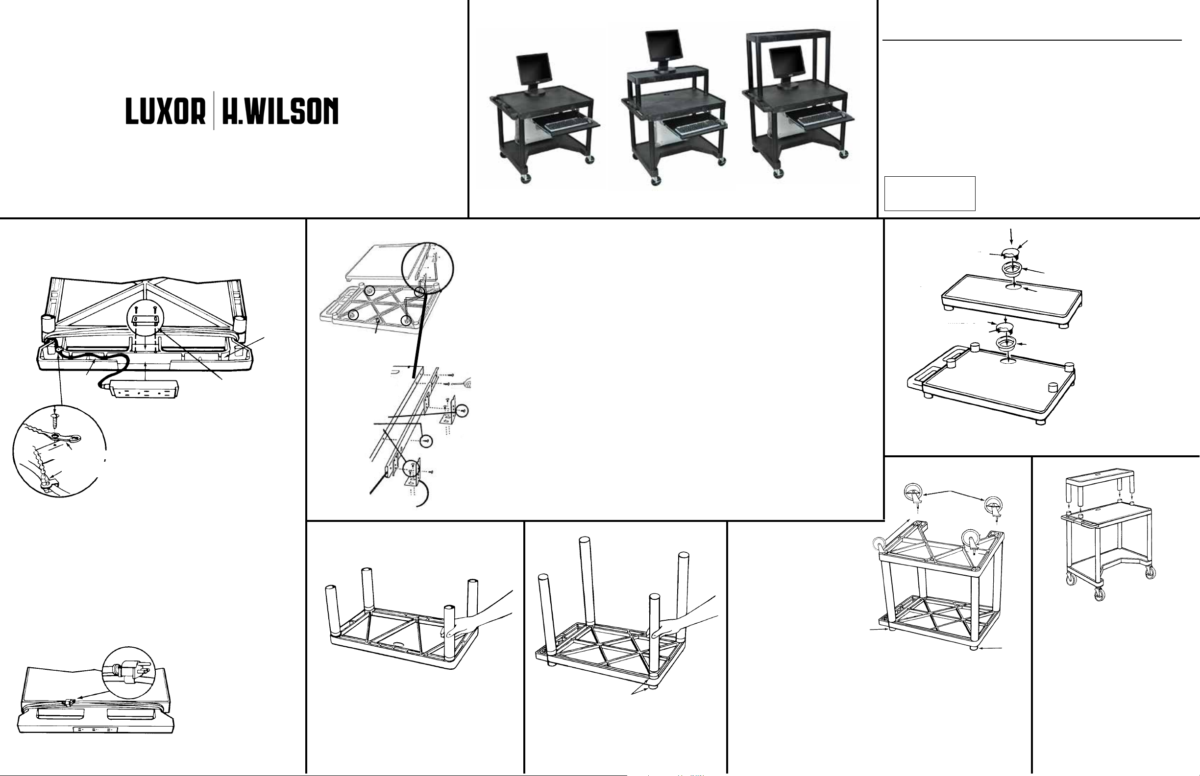
IMPORTANT
The electrical unit & pullout shelf
should be assembled first.
CORD
RETAINING
TRACK #1
3 PLUG UNIT
A
CORD MANAGEMENT TIE
TIE IS IN SECURED
POSITION
1
POWER CORD
MANAGEMENT TIES
Firmly seat electrical assembly 3 plug unit into
handle plug housing as illustrated. Secure with
power cord plug retaining bracket. Thread cord
through cord retaining track and out the opening in the side of the handle.
2
Secure power cord management tie into starter
hole with sheet metal screws. See illustration
A. Secure with power cord management tie by
wrapping tie around cord and fastening. Cut off
any unnecessary extra length of tie.
CORD
RETAINING
TRACK #2
POWER CORD PLUG
RETAINING BRACKET
3
Wrap the cord
around the handle.
4
For safety and neat
appearance secure cord
plug to cord by utilizing
plug snap.
PULLOUT SHELF ASSEMBLY: CART ASSEMBLY:
2A. To install metal pull-out shelf, first turn workstation top shelf upside down, locate the four “L”
bracket support members as shown in step 1.
2B. Secure “L” brackets to “L” bracket support members using two 5/8 sheet metal screws per
bracket. Do not fully tighten screws at this time. Note: “L” brackets must face each other pointing in towards center of workstation shelf.
2C. Next, identify left runner from right runner. This is done by extending runner fully to locate the
CORD GUIDE COVER
LEM32T / LEM32TT
TERMINAL
PLATFORM
three holes used to attach to metal shelf. This portion of the runner with holes must face toward
METAL
KEYBOARD
SHELF
front of metal shelf. Turn metal shelf upside down and install runners on each side using three
sheet metal screws on each side. Special Note: Remember all assembly is being done upside
down. Position assembled shelf and runner between “L” brackets to determine proper spacing
of “L” brackets. Carefully remove metal shelf and fully tighten “L” brackets.
2D.Use self-tapping screws to secure runner to “L” brackets. For maximum clearance use hole on
GROMMET CAP
CORD GUIDE COVER
“L” bracket that is farthest away from workstation top shelf.
2E.Install grommet ring by tapping into place with rubber mallet. Snap off cord guide cover from
grommet cap so equipment plug may be run through grommet to plug unit, then insert grom-
Self Tapping Screws
Sheet Metal Screws
(in Runner Bag)
met cap into grommet ring.
3A. Lay top shelf (with handle) ribbed side up on a smooth surface. Push all 4 legs onto leg posts.
3B.Position bottom shelf with open cut-out facing toward the front, ribbed side up, over the 4 legs
MIDDLE SHELF
of the top shelf as illustrated. Insert leg posts into legs. Using a rubber mallet, firmly hammer
bottom shelf into legs until all four legs are seated (flush) against the surfaces of both shelves.
RUNNER
“L” BRACKETS
3C.Push the four casters firmly into the holes in each corner of the bottom shelf. :
ers must be fully seated. Tap firmly with rubber mallet to properly seat casters. Turn your Endura
workstations right side up. It is now ready to use.
LOCKING CASTERS
FRONT
For LEM32T &
LEM32TT
TERMINAL
TFORM
PLA
BACK
LEG
POST
4.
Position bottom shelf with open cut-out facing toward the front, ribbed
side up, over the 4 legs of the top shelf as illustrated. Insert leg posts
2.
Lay terminal platform (long narrow shelf with
grommet hole) ribbed side up on a smooth
surface. Push 1 set of short legs onto leg
posts. Set aside temporarily and continue
with step No. 3.
LEG POST
3.
Lay middle shelf (with handle) ribbed side
up on a smooth surface. Push all 4 long legs
onto leg posts.
into legs. Using a rubber mallet, firmly hammer bottom shelf into legs
until all four legs are seated (flush) against the surfaces of both
shelves.
5.
Push the four casters firmly into the holes in each corner of the bottom
shelf. Important: casters must be fully seated. Tap firmly with rubber mallet
to properly seat casters. Turn your Endura Workstation right side up.
GROMMET CAP
GROMMET
CABLE GROMMET HOLE
GROMMET RING
6.
Set terminal platform as complet-
LEG
POST
ed in Step No. 2 right side up and
set its legs onto leg posts of
middle shelf. Grommet hole should
be to the back of terminal
platform. Firmly hammer terminal
platform with legs onto leg posts of
middle shelf until legs are seated
(flush) against the surface of
middle shelf and terminal
platform. Your Endura Computer
Workstation is now ready for use.
RING
1.
Install grommet
rings by tapping into
place with rubber
mallet. Snap off cord
guide cover from
grommet cap so
equipment plug may
be run through
grommet to plug
unit, then insert
grommet cap into
grommet ring.
Upated 10/5/12
 Loading...