

Page 1
Instruction Sheet - LE Model Tables
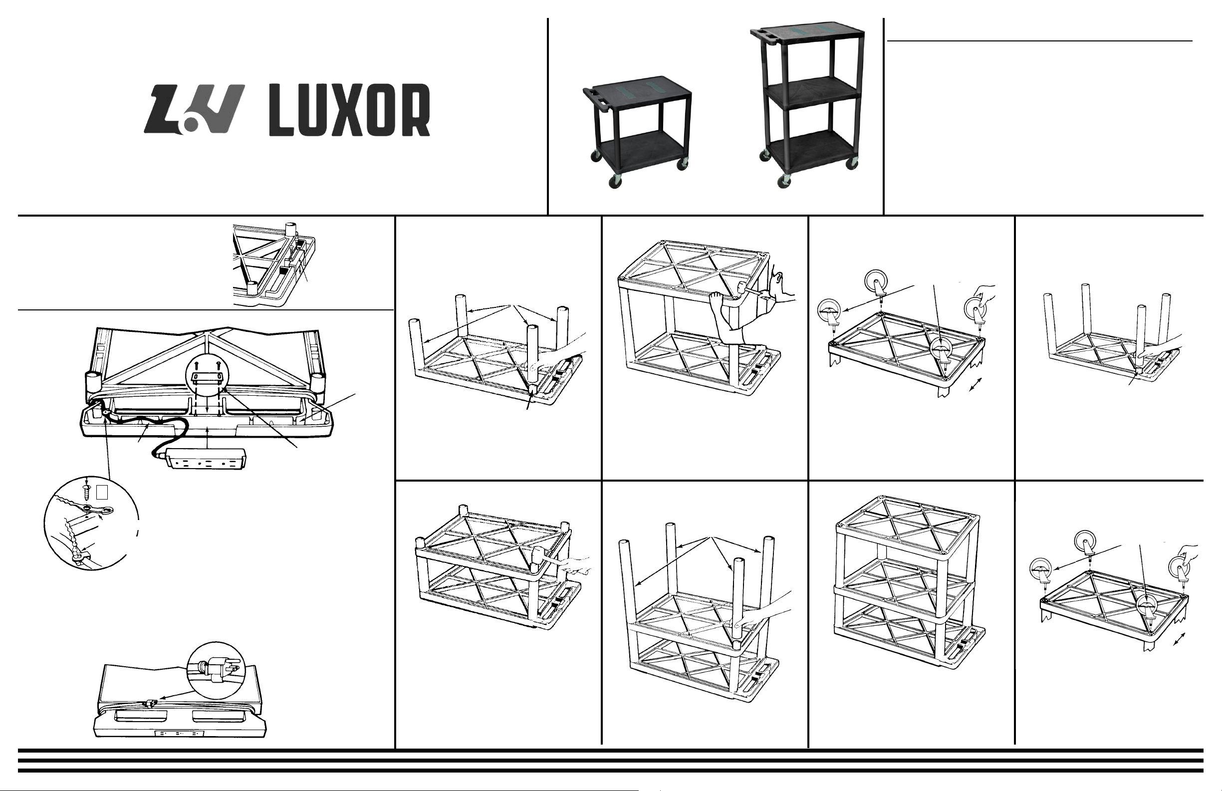
Models LE-26 and LE-27 Two Shelf Mobile Tables
Models LE-34, LE-40, LE-42, LE-48 and LE-54 Three Shelf Mobile Tables
Customer Service Dept
2245 Delany Rd
Waukegan, IL 60087
Ph: 847/244-1800 • 800/323-4656
Fax: 847/244-1818 • 800/327-1698
LE - Two Shelf Model LE - Three Shelf Model
PARTS LIST
Models LE26 & LE27
1 - Bottom shelf with casters sockets
1 - Top shelf with handle
4 - Long legs
4 - Casters (2 w/brake)
1 - Plug housing cover
2 - Sheet metal screws
Optional Electric Assembly:
1 - Electric cord
1 - Power cord retaining bracket
1 - Cord tie
- Sheet metal screws
3
Models LE34, LE40, LE42,
LE48 & LE54
1 - Bottom shelf with casters sockets
1 - Top shelf with handle
1 - Center shelf with eight leg posts
4 - Short legs
4 - Long legs
4 - Casters (2 w/br
ake)
1 - Plug housing cover
2 - Sheet metal screws
Tools Required:
1 - Rubber Mallet
1 - Slotted Screwdriver
IMPORTANT:
If your LE table does not have the Optional
Electrical Assembly start by closing the electric plug housing in the handle of the top shelf
as illustrated. If your LE table has the Optional
Electric Assembly, see assembly instructions
below. Start by assembling electric.
CORD
RETAINING
TRACK #1
A
CORD MANAGEMENT TIE
TIE IS IN SECURED
POSITION
POWER CORD
MANAGEMENT TIES
3 PLUG UNIT
PLUG
HOUSING
COVER
CORD
RETAINING
TRACK #2
POWER CORD PLUG
RETAINING BRACKET
1
Firmly seat electrical assembly 3 plug unit into
handle plug housing as illustrated. Secure with
power cord plug retaining bracket.Thread cord
through cord retaining track and out the opening in the side of the handle.
2
Secure power cord management tie into starter
hole with sheet metal screws. See illustration
A. Secure with power cord management tie by
wrapping tie around cord and fastening. Cut off
any unnecessary extra length of tie.
Models LP-26 and LP-27
LONG LEGS
LEG POST
1
Lay top shelf (with handle) ribbed side up on a
smooth surface. Push all 4 legs onto leg posts.
2
Position bottom shelf, ribbed side up, over the 4
legs and insert leg posts into legs. Using a
rubber mallet, firmly hammer bottom shelf into
legs until all 4 legs are seated (flush) against the
surfaces of both shelves.
*Models LE34 and LE40
use long legs second.
*Models LE42, LE48 and
LE54 use short legs second.
FOR BIG WHEEL
ASSEMBLY.
See instructions
in Big Wheel
hardware pack.
PLACE LOCKING CASTERS
AS ILLUSTRATED
BACK
FRONT
3
Push the four casters firmly into the holes in
each corner of the bottom shelf. Important:
Casters must be fully seated. Tap firmly with
rubber mallet to properly seat casters. Turn your
LP table right side up. It is now ready for use.
Models LE-34, LE-40, LE-42, LE-
48 and LE-54
*Models LE34 and LE40 use short legs first.
*Models LE42, LE48 and LE54 use long legs first.
LEG POST
1
Models LE-34 and LP-40: Lay top shelf (with
handle) ribbed side up on a smooth surface.
Push all 4 short legs onto leg posts.
Models LE-42, LE-48 and LE-54: Lay top
shelf (with handle) ribbed side up on a smooth
surface. Push all 4 long legs onto leg posts.
FOR BIG WHEEL
ASSEMBLY.
See instructions
in Big Wheel
hardware pack.
PLACE LOCKING CASTERS
AS ILLUSTRATED
BACK
3
Wrap the cord
around the
handle.
4
For safety and neat
appearance secure cord
plug to cord by utilizing
plug snap.
2
Position center shelf (with 8 leg posts) ribbed
side up, over the 4 legs and insert leg posts into
legs. Using a rubber mallet, firmly hammer center shelf into legs until all 4 legs are seated
(flush) against the surfaces of both shelves.
3
Push remaining 4 legs into leg posts of center
shelf.
4
Position bottom shelf, ribbed side up, over the 4
legs and insert leg posts into legs. Using a
rubber mallet, firmly hammer bottom shelf into
legs until all 4 legs are seated (flush) against the
surfaces of both shelves.
FRONT
5
Push the four casters firmly into the holes in
each corner of the bottom shelf. Important:
Casters must be fully seated. Tap firmly with
rubber mallet to properly seat casters. Turn
your LE table right side up. It is now ready for
use.
Page 2

Instruction Sheet - Endura Mobile Cabinet Tables Instructions for LE-C Units with locking Cabinet
Models LE26C, LE27C
Customer Service Department
Luxor
2245 Delany Road
Waukegan, IL 60087
Ph: 847/244-1800 • 800/323-4656
Fax: 847/244-1818 • 800/327-1698
LE27C
PARTS LIST
Models LE27C, LE26C
1 - Top shelf w/handle 1 - Grommet Cap
1 - Bottom shelf w/caster sockets 1 - Cord guide cover
4 - Legs 2 - Grommet rings
2 - Cabinet side panels 1 - Rubber Band
1 - Back Panel 4 - Small ‘U” brackets
1 - Door in frame 1 - Large “U” bracket
1 - Power cord 1 - Cord wrap bracket
4 - Casters 2 with brake 2 - Stove bolts
8 - 1 3/4” machine screws
Tools Required:
Rubber mallet
If you did not get an
electric assembly with
your cart start by closing
the electric plug housing
in the handle of the top
shelf as illustrated below.
PLUG
HOUSING
COVER
NOTE: Model LE-27C had double doors.
RUBBER BAND
BOTTOM
SHELF
LEG POST
1
With bottom shelf facing up push all four legs
onto leg posts. Using rubber mallet hammer legs
firmly into position. Legs must be seated (flush)
against the shelf surface. Place rubber band
around legs to aid in the assembly of cabinet
side panels and doors.
TOP
SHELF
TOP VIEW
LEGS
SIDE
PANEL
SIDE VIEW WITH
PANEL SEATED
INSIDE SHELF LIP
2
Install the side panels first. Slide panels down
between legs until they are nested inside the
shelf lip and flush against the shelf surface.
Rubber band will hold legs and side panels in
place while installing back panel and front door.
CORD
GUIDE
COVER
GROMMET RING
GROMMET HOLE
GROMMET RING
STOVE
BOLTS
CORD
WRAP
BRACKET
BRACKET
3
Install the back panel in the same manner as side
panels. Install grommet ring into grommet hole.
Insert two stove bolts as illustrated through “U”
bracket into back panel and through slots in cord
wrap bracket. Align the cord wrap bracket onto
stove bolts from the outside of back panel, and
secure with two kep nuts.
PLACE LOCKING CASTERS
AS ILLUSTRATED
BACK
KEP
NUT
“U”
GROMMET
HOLE
“U”
BRACKET
INSIDE BACK
PANEL
4
Press 3-outlet power cord into “U” bracket and feed
remaining cord through grommet hole and wrap
remaining cord around cord wrap bracket. For safety
and neat appearance, secure cord plug to cord with
plug snap.
CORD WRAP
BRACKET
PLUG SNAP
OUTSIDE
BACK PANEL
5
Install door panel same as back panel with door
handle at top. Be sure door opens outward and
door frame is also placed between legs and nested
flush on the shelf floor.
6
Begin seating of top shelf by holding door panel,
leg and side panel as illustrated. Gently tap corner
posts into legs until all posts are partially inserted
into legs. Repeat hammering action more firmly
going around to each corner, being certain that
each panel nests inside the lip of the top shelf.
Repeat this action until top shelf is fully nested.
7
Install grommet ring and grommet cap into top shelf.
For tables with electric assembly, snap off cord
guide cover from grommet cap to allow equipment
plug entry. Insert grommet cap into grommet ring.
FRONT
8
Push the four casters firmly into the holes in
each corner of the bottom shelf. Important: cast-
ers must be fully seated. Tap firmly with rub
mallet to properly seat casters. Turn your
Endura Table right side up.
ber
Page 3

Instruction Sheet - Endura Mobile Cabinet Tables
Models LE-34C, LE-40C, LE-42C, LE-48C and LE-54C
Customer Service Department
Luxor
2245 Delany Road
Waukegan, IL 60087
Ph: 847/244-1800 • 800/323-4656
Fax: 847/244-1818 • 800/327-1698
LE-54C
LE-40C
PARTS LIST
Models LE-34C, LE-40C, LE-42C, LE-48C, LE-54C
1 - Top shelf w/handle 1 - Door in frame
1 - Center shelf w/eight leg posts 1 - Grommet cap
1 - bottom shelf w/caster sockets 1 - Cord guide cover
4 - Short legs 1 - Grommet ring
4 - Long legs 1 - Rubber band
2 - Cabinet side panels
1 - Back panel
4 - Casters 2 with brake
Tools Required:
Rubber mallet
LE-42C
1
IMPORTANT
The electrical unit should
be assembled first.
If your Endura Cabinet
able does not have the
T
Electrical Assembly and
Cable-Track™ Cord
Management System,
start by closing the electrical plug housing in the
handle of the top shelf as
illustrated below.
Units with electric receive following parts:
1- Cord guide cover
1- Cord wrap
4- Cord ties
1- L-bracket
6- Screws
1- Power cord
18” LEG
RUBBER BAND
BOTTOM
SHELF
LEG POST
2
With bottom shelf facing up push all four 18” legs
onto leg posts. Using rubber mallet hammer legs
firmly into position. Legs must be seated (flush)
against the shelf surface. Place rubber band
around legs to aid in the assembly of cabinet
side panels and doors.
TOP VIEW
SIDE
PANEL
SIDE VIEW WITH
PANEL SEATED
INSIDE SHELF LIP
3
Install the side panels first. Slide panels down
between legs until they are nested inside the
shelf lip and flush against the shelf surface.
Rubber band will hold legs and side panels in
place while installing back panel and front door.
CENTER
SHELF
LEGS
4
Install the back panel in the same manner as
shown in Step #3. NOTE: Cabling hole in back
panel should be toward the top.
CORD
GUIDE
COVER
TOP
SHELF
GROMMET CAP
GROMMET RING
NOTE: Models LE-40C, LE-48C, and LE-54C
have double doors.
5
Install door panel same as back panel, with
door handle at top.
PLACE LOCKING CASTERS
AS ILLUSTRATED
PLUG
HOUSING
COVER
Units without electric receive following parts:
1- Cord guide cover
2- Screws
1- Plug housing cover
6
Begin seating of center shelf by holding door panel,
leg and side panel as illustrated. Gently tap corner
post into leg. Repeat on all 4 sides until all posts
are partially inserted into legs. Now repeat hammering action more firmly going around to each
shelf post and driving the leg posts more securely
into the legs.
Top of panels and door frame must be nested into
the underside of the center shelf lip in the same
manner as the bottom shelf.
CENTER SHELF
7
Push remaining 4 legs onto center shelf posts as
illustrated. Place top shelf (with handle) onto legs.
Insert leg posts into legs of top shelf. Using rubber
mallet, firmly hammer top shelf into legs until all
four legs are seated against shelf surface. install
grommet ring and grommet cap into top of shelf.
For tables with electric assembly, snap off cord
guide cover form grommet cap to allow equipment
plug to be run through grommet. Insert grommet
cap into grommet ring. Remove rubber band.
BACK
FRONT
8
Push the four casters firmly into the holes in
each corner of the bottom shelf. Important: casters must be fully seated. Tap firmly with rubber
mallet to properly seat casters. Turn your
Endura Table right side up.
 Loading...