

Page 1
LCD Mount Instructions
AVJ42-LCD, W42A-LCD
01/31/13
1/2
www.luxorfurn.com
www.hwilson.com
3
4
5
LCD Mount Box Base Unit 30 in Chrome Tube Box
2
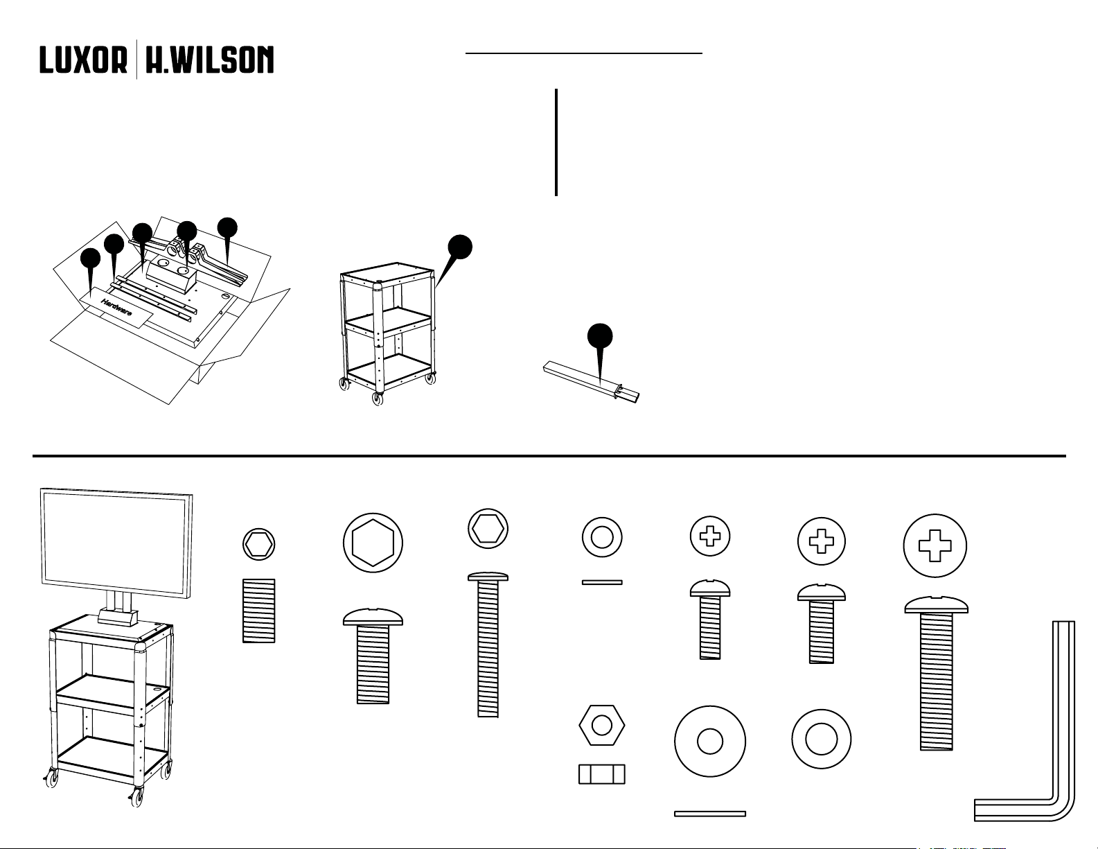
Parts ListTools Required
- Phillips Screwdriver
- 8mm Wrench
1
7
LCD Mount Component List
1 - TV bracket x2
2 - Base block x1
3 - Base plate x1
4 - L bracket x2
5 - Hardware bag x1
6 - Chrome tube x2
7 - Base unit
6
Hardware Bag
5a - M8x16 set screw x8
5b - M8x20 cap screw x5
5c - M5x35 cap screw x4
5d - M5 metal washer x4
5e - M5 locking nut x4
5f - M5x16TV screw x4
5g - M6x16TV screw x4
5h - M8x35TV screw x4
5i - TV washer x4
5j - TV spacer x4
5k - Allen wrench x3
5a 5b 5c 5d 5f 5g 5h
5j5i5e 5k x3
Page 2
www.luxorfurn.com
www.hwilson.com
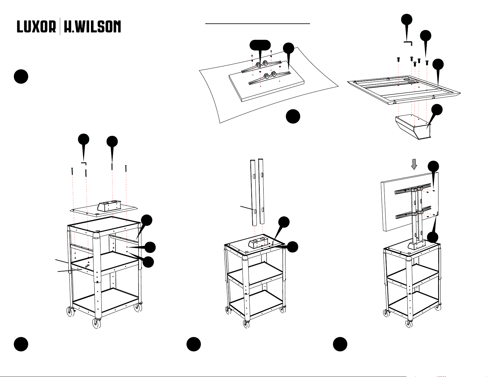
This assembly requires 2 people. Place your TV on
1
a soft surface. Determine what TV screw works with
your TV (5f, 5g or 5h). Use the metal washer (5i) if
you are using (5f) or (5g). If your TV has pockets use
the plastic spacer (5j) in the pocket with (5h). Attach
the 2 TV Brackets (1) to your TV with the included
hardware using a Phillips screw driver (not included).
5k
5c
LCD Mount Instructions
AVJ42-LCD, W42A-LCD
5f-5j
1
2
Using the supplied Allen
wrench (5k), attach the
base block (2) to the base
plate (3) with 5 screws (5b).
5k
01/31/13
2/2
5b
3
2
5a
Chrome Tube (6)
4
5d
Base unit (7)
5k
5a
5e
Wrench
Using an Allen wrench (5k) and a wrench
(not included), attach the assembled unit
3 4 5
to the Base unit (7) with 2 L brackets (4), 4
screws, 4 washers and 4 nuts (5c, 5d & 5e).
Install the 2 chrome tubes (6) to the
assembled unit. Secure in place with
4 set screws (5a).
5k
With assistance, attach the TV to the
assembled unit. Secure in place with 4
set screws (5a). You have completed the
assembly of your LCD Mount.
Page 3

01/31/13
www.luxorfurn.com
www.hwilson.com
Adjustable Height
Metal Cart Instructions
AVJ42, W42A
C
Parts List
Non-slip mat
A x1 B x1 C x4
A
Cabinet comes
pre-assembled
on units that
include a cabinet.
Tools Required
- Phillips Screwdriver
- Rubber Mallet
- Pliers or Adjustable Wrench
D x4 E x4
A
E
D
B B B
1 2 3
Position the bottom shelf B so that the
caster holes are facing up. Insert caster C
into the caster holes on the bottom of shelf
B. Use a mallet to set the casters properly.
Flip bottom shelf B so that it is on its side.
Set top shelf A so that it overlaps bottom
shelf B. Align the screw holes so that the
top shelf A is at the desired height.
E
Insert screw D through the aligned screw hole
of A and B and fasten nut E with pliers and
screwdriver. Place Non-slip mat on desired
shelf. The cart is now complete.
D
Page 4

01/31/13
www.luxorfurn.com
www.hwilson.com
Electric Assembly
Instructions
Number of outlets
may vary.
Parts List
Tools Required
- Screwdriver
A x1 B x1 C x2 D x2
D
D
(Plastic or Metal
Mounting Surface)
C
1
Push screw C through electric outlet A. Make sure
the electric outlet A and cord wrap B align with the
mounting surface screw holes. Push screw C through
cord wrap B and the mounting surface screw holes.
Use wing nut D and screwdriver to fasten.
B
A
C
 Loading...