

Page 1
Instruction Sheet
PARTS LIST FOR SHELF ASSEMBLY
Model AVJ422KB4
Customer Service Dept
2245 Delany Rd
Waukegan, IL 60087
Ph: 847/244-1800 • 800/323-4656
Fax: 847/244-1818 • 800/327-1698
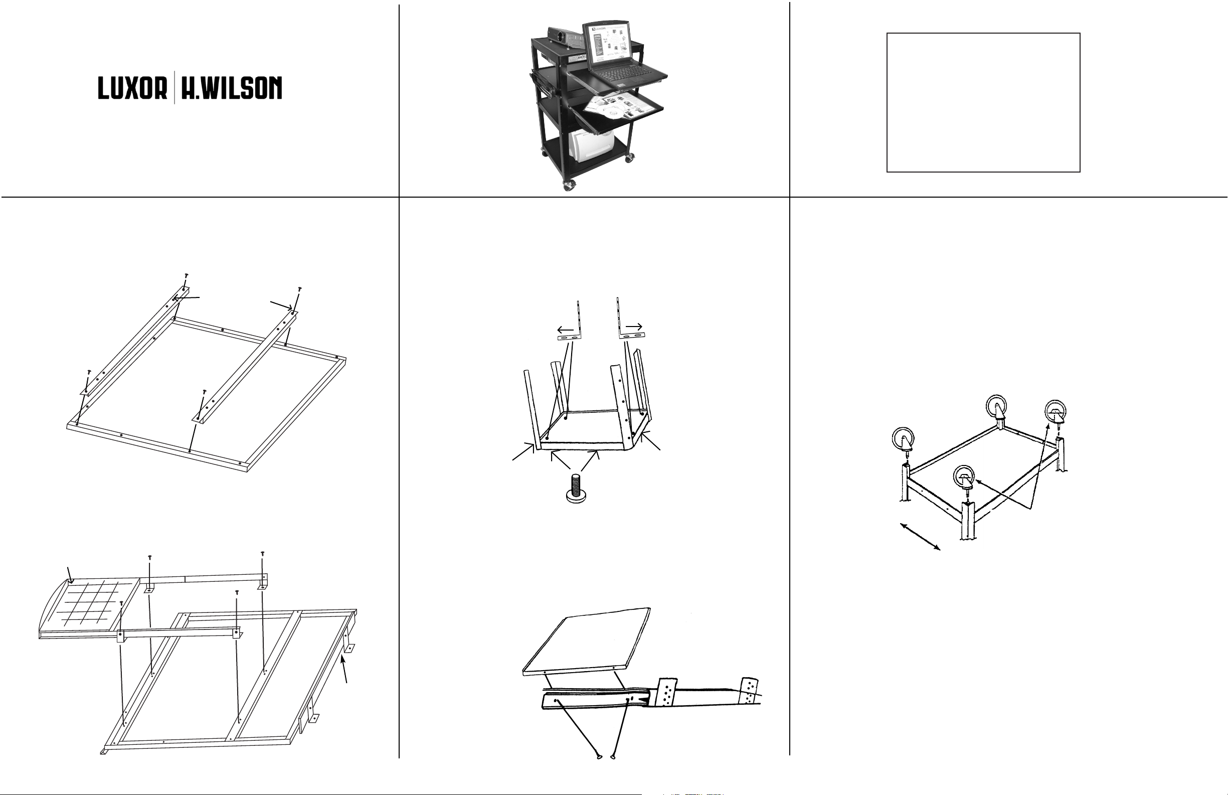
Step 1
(Note: For the mouse shelf to pull out to the right, use the first set
of holes on the left side and the third set of holes.)
MOUSE SHELF ASSEMBLY
Mouse shelf rail
AVJ422KB4
Step 2
Mount the four L-Brackets to the holes on the top shelf
using 4- bolts, 4- washers and 4- nuts. Be sure brackets are
pointing outward. Then align the two threaded holes on the
side of the runners to the hole on the brackets and attach
with two pan head screws. Do the same to the other side.
8 - L-brackets
ashers
8 - W
8 - Bolts
8 - Nuts
8 - Self tapping screws
32 - Sheet metal screws
4 - Runners
2- Keyboard Shelf Racks
5. Turn bottom stand assembly upside down on a smooth surface. Push
the four casters firmly into the caster socket holes in bottom of each leg
as illustrated.
Attach the mouse shelf support bars to the first holes and third holes on the bottom of
the keyboard shelf with 4-sheet screws. Then align the brackets on the mouse shelf to
the holes on the support bars and attach using 8 sheet metal screws.
Mouse shelf
Runners shown
attached for
illustrative
purposes, do not
attach until step 4.
Top
Top Shelf
Step 3
Repeat step 2 for second shelf.
Step 4
Extend runners outward and align the holes on the side
of the keyboard
to the first hole
and last hole on
the slides, and
attach with two
sheet metal
screws on each
side. Repeat for
second shelf.
Back
Place locking casters as
illustrated
Front
Page 2
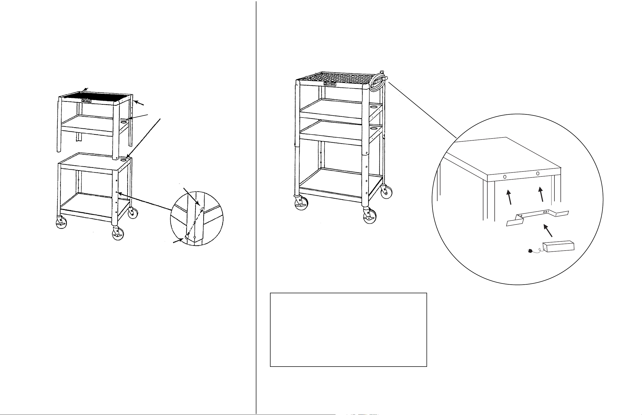
6. a. Attach second shelf to top stand assembly at desired height using 4 bolts
and kep nuts. Position top stand assembly over bottom stand assembly,
as illustrated.
Note: Be sure cabling hole in corner of top and middle shelves line up on top
of each other.
b. Adjust top stand assembly up or down to desired height. Align holes in all
four legs, insert bolts and fasten with four kep nuts, as illustrated. Place
rubber mat on top shelf.
Cabling Holes
Top
Stand
Assembly
7. ELECTRIC ASSEMBLY
Bottom
Stand
Assembly
Kep Nut
Bolt
PARTS LIST FOR STEPS 5, 6, AND 7.
1 - Set of casters
1 - Power cord
1 - Cord wrap
1 - Rubber mat
Place metal cordwrap onto metal top shelf making sure that
the holes on the cordwrap align with the holes on the shelf.
Place the two screws through the holes of the electrical
assembly. Place the electrical assembly with the two screws
through the holes of the cordwrap and mounting bracket.
Secure screws with wingnuts.
FOR ATTACHING TOP AND MIDDLE SHELF TO BOTTOM HALF
8 - Kep nuts
8 - 3/4" bolts
17Sep07
 Loading...