

Luxor ZD, ZDC Owner's Manual
Owner’s Manual and Installation Instructions for
Luxor ZD and Luxor ZDC
LUXOR
ZD
ZDC
LED Landscape
Lighting Controller

2
Table of Contents
Luxor® Overview
3 Luxor Components
4 Glossary of Terms
4 Safety Information
Installing the Luxor Transformer
5 Step 1 – Location Selection
5 Step 2 – Mounting Transformer
6 Step 3 – Running Cable to the Fixtures
Cabling Methods 8
Connecting Cables at the Terminal Block 8
Operating the Luxor
9 Navigating the Luxor
9 HOME Screen
9 ACTIVITY Screen
10 DIAGNOSTICS Screen
11 Setup Screen
Time/Date 11
Language 12
Location 12
Assign 13
Network 13
Restrict 13
Backup 14
Contact Card 14
15 Assigning Light Fixtures into Groups
16 Setting up Programs
16 Themes
17 Manual Mode
18 Color
Color Palette 18
Incorporating Color into Luxor 19
Mixing FX LED, ZD, and ZDC 21
22 Using Other Devices with the Luxor
23 Shutdown
24 Luxor Linking System Setup
Care and Maintenance
27 Regular Preventive Maintenance
28 Troubleshooting
29 Firmware Updates
30 Fuse Replacement
30 System Reset
Facepack Reset 32
Database Reset 32
33 Chassis Indicator Lights
34 Warranty
3
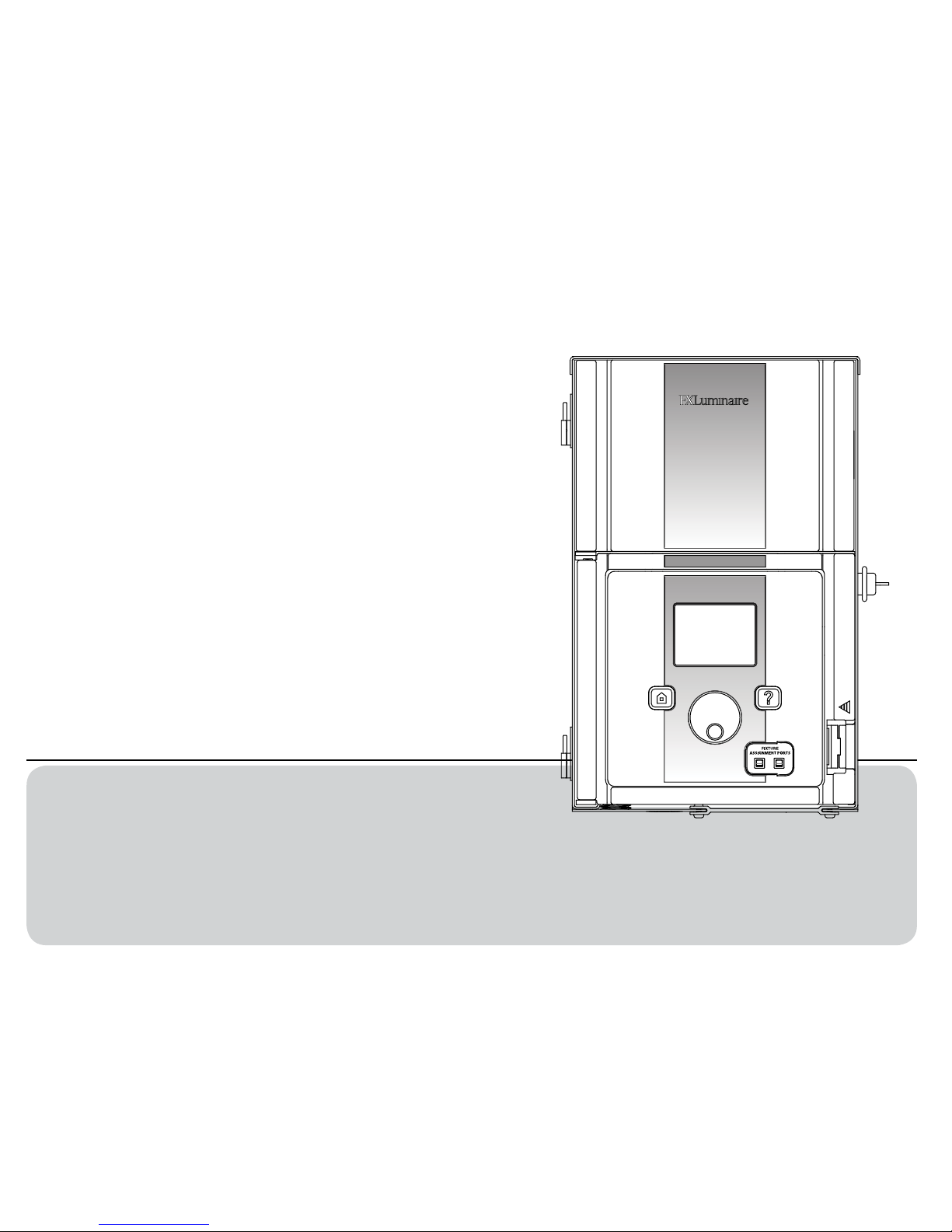
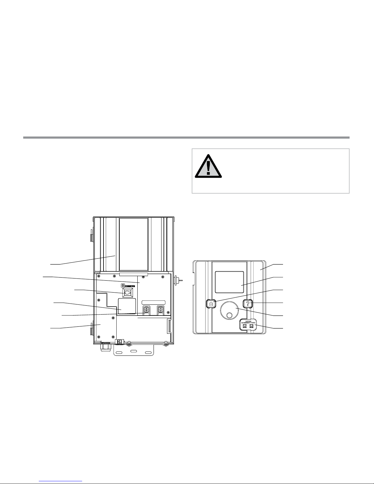
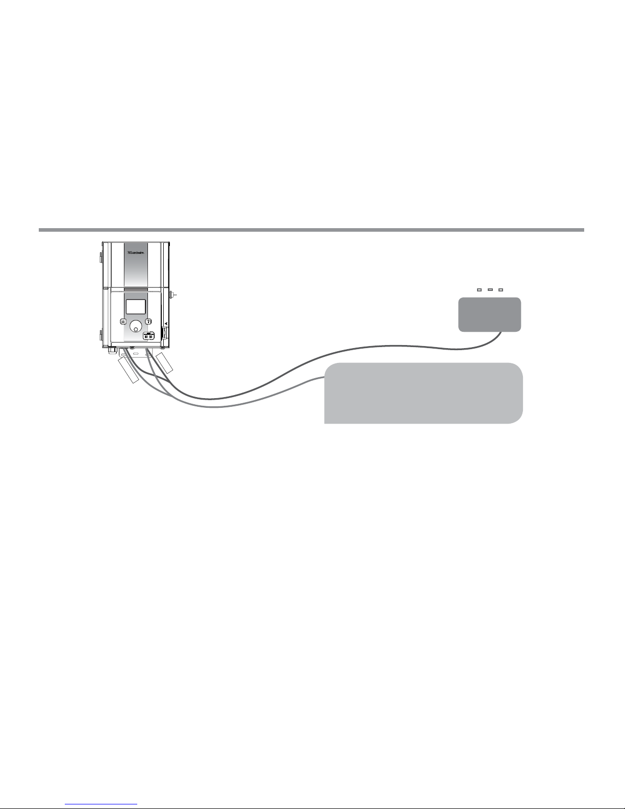
LUXOR® ZD/ZDC Overview
Core Cover
Chassis
Facepack Connection
Chassis LED
Terminal Blocks
Fuse Cover
Facepack
LCD Screen
Home Button
Help Button
Clickable Scroll Wheel
Fixture Assignment Ports
Luxor Components
The Luxor ZD/ZDC is a lighting transformer and controller capable
of controlling groups of lights that are initiated by programmed
events. These events are adjustments of light intensity at set times.
All lights within a system are communicated with and powered via
two wire connections. All lights within a system communicate with
the same two wire connections that also power the system.
NOTE: The Luxor is intended for use with FX
LED xtures or devices containing FX Zoning,
Dimming, or Color Technology. Use of other
xtures is not recommended due to the absence
of communication capabilities. The Luxor is not for
use with incandescent xtures.

4
Luxor® ZD/ZDC Overview
Glossary of Terms
Group: An addressed set of lights that is designated numerically
and controlled as a set by the controller.
Theme: A predetermined set of groups, intensities, and colors
(ZDC only) called to action by the program or manual functions.
Fixture/Luminaire: Light unit that contains an FX LED board or
device with FX Zoning, Dimming, or Color capabilities.
Intensity: Value indicating the measurable amount of brightness,
from 1% to 100%.
Event: The initiation, adjustment, or conclusion of a selected theme
or group with specic intensity and/or color settings.
Duration: The length of time an event will run.
Hue: The primary attribute of a color. It is represented by numeric
values between 0 and 359.
Saturation: The richness of a color mixed with white light,
from 0% to 100%.
Color: The visual combination of hue and saturation.
Primary Controller: Luxor ZD/ZDC controller containing a facepack
Satellite Controller: Controller without a facepack
Safety Information
These cord-connected units consist of step-down, isolated twowinding type transformers, circuit breakers, and associated circuitry
intended to supply power to low-voltage, submersible fountain
lighting xtures.
WARNING — Risk of Electric Shock. Install power unit 5 feet
or more from a pool or spa and 10 feet or more from a fountain.
Where the power unit is installed within 10 feet of a pool or spa
connect power unit to a GFCI-protected branch circuit. Do not use an
extension cord when connecting the power unit to the 120V source.
The grounding conductor shall be 12 AWG minimum. Outdoor power
unit shall be connected to a GFCI-protected hooded ush type cover
plate receptacle marked “Wet Location” while in use.
Caution: The supply circuit for the landscape lighting system shall be
protected by a Class A type ground fault circuit interrupter, unless it
is provided with the landscape lighting system. This device is
accepted as a component of a landscape lighting system where the
suitability of the combination shall be determined by local inspection
authorities having jurisdiction. Do not connect two or more power
supplies in parallel. Not for use in dwelling units. This presents a risk
of re. Do not place insulation under terminal plate. Check connector
aer installation.
Circuit Protection
11 amps for 150 watt power controller
22 amps for 300 watt power controller
5
Installing the Luxor® ZD/ZDC Transformer
Step 1: Locating the Transformer
1. Locate transformer(s) in a well-ventilated area away from direct
irrigation spray and central to the proposed installation site of the
majority of the lighting xtures. The primary goal is to minimize
the length of cable runs from your transformer to the lighting
xtures, which minimizes voltage drop and cable size. A common
mistake is to locate the single transformer on the service side of
the house or in the garage, which might result in excessively long
cable runs to reach lighted areas.
Transformer(s) with power cords must be located adjacent to
a 120-volt GFCI-protected exterior electrical receptacle. If a
120-volt power source is not available at the desired transformer
installation location, it is advised that you hire a licensed
electrician to run a dedicated 120-volt, 15-amp circuit to the
desired location. For the international/export Luxor version,
the previously mentioned information applies for 230-volt,
10 amp circuits.
2. Test all existing receptacles with both a receptacle tester and a
digital voltmeter or amp clamp to verify proper wiring and voltage
at the receptacle.
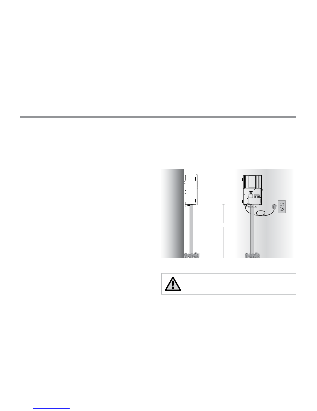
Step 2: Mounting Transformers
Wall Mount Installation:
1. Install all transformers a minimum of 12" above nish grade, as
measured from nish grade to the bottom of the transformer and
according to code.
2. Drill pilot holes into mounting surface, insert anchors and install
screws into anchors leaving approximately ⁄" of thread exposed
on the screw. Mount transformer on screw.
3. Use a level and a pencil to determine and mark locations for
bottom anchors. Remove transformer from wall. Drill bottom
anchor holes and install anchors.
4. Place transformer back on top of uppermost mounting screw and
install screws into anchors at bottom of transformer to secure
it to the wall.
NOTE: When installing the Luxor Wi-Fi module,
consider increasing the installation height to improve
signal strength and visibility of the screen.
Mounting
Brackets
1⁄" conduit
12" minimum
1⁄" conduit
Power Cord
Finished Grade
120 volt
receptacle
with weatherproof cover
SIDE VIEW FRONT VIEW
6
Installing the Luxor® ZD/ZDC Transformer
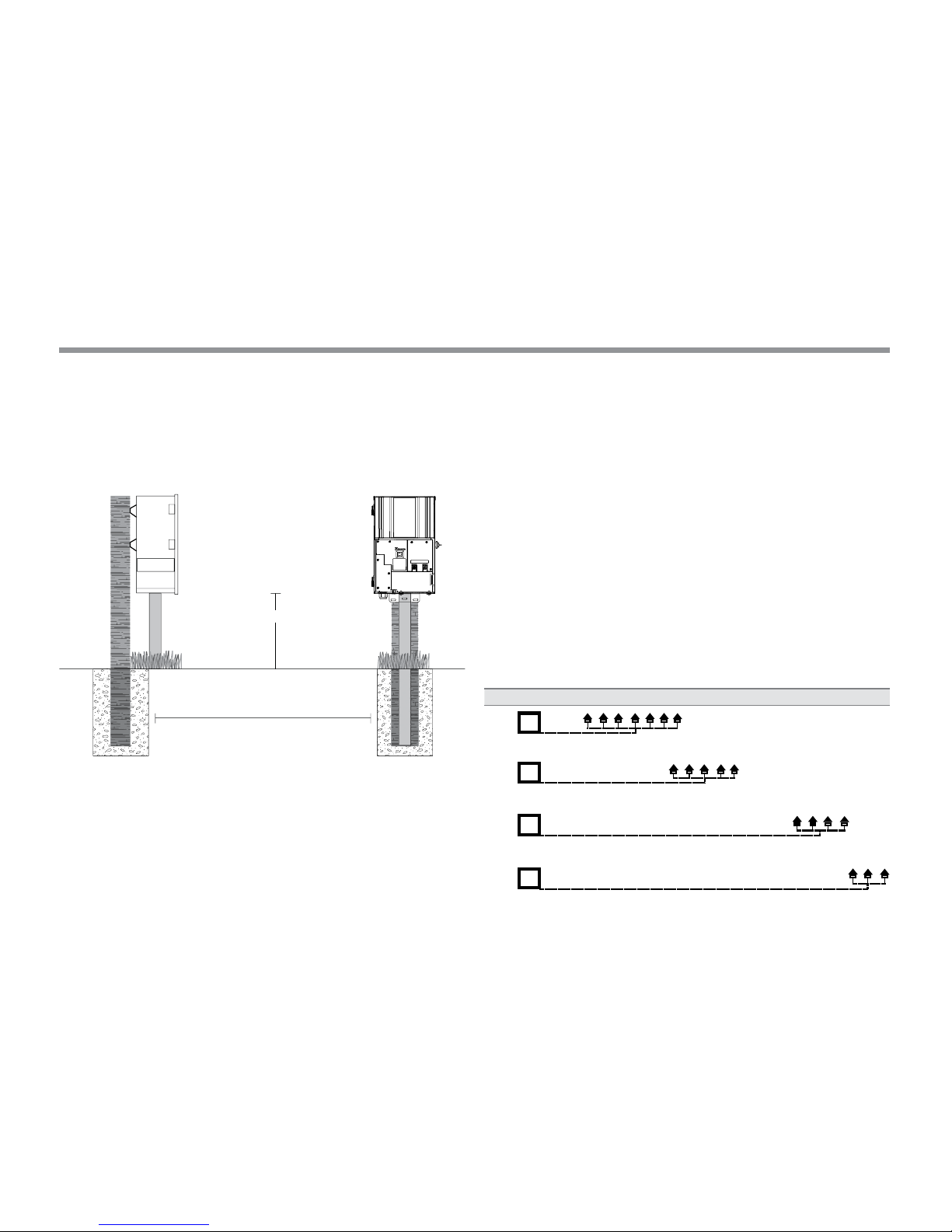
Post Mount Installation: Install pressure treated 4" x 4" x 36" (min)
post in concrete footing. Repeat wall mount installation instructions
from page 5, without the use of wall anchors.
•
•
•
•
For additional information regarding installation techniques, visit
www.fxl.com, and click on the Resources and Tools link.
All Luxor Series Transformers come equipped with a 5-foot,
12-gauge, 3-prong electrical power cord. Only use the Luxor power
cord in conjunction with a GFCI-protected 120 volt exterior receptacle
(or 230 volt for international/export version).
Step 3: Running Cable to the Fixtures
Once the transformer has been installed and determined all xture
locations, the next step is to run the correct size cable from the
transformer to the xtures. FX LED xtures require between 10 and 15
volts for optimal operation and longevity. This is accomplished by the
following:
1. Grouping xtures into distance zones as illustrated below. Do not
have a xture that is 10 feet away from the transformer on the
same cable run as one that is 100 feet away.
2. Use the proper cabling method for the application. Try to
center-load all cable runs when possible to minimize the voltage
dierential between xtures.
3. Use the correct size cable to accommodate voltage drop.
As a general rule of thumb, limit the wattage load per cable
run to no more than 160 watts.
LOADS PER CABLE
Add cable runs as necessary
T
T
T
T
Close-Zone 0–40'
Mid-Zone 40–80'
Far-Zone 80–120'
Out There-Zone 120–160'
12 Gauge: 160 watts max. 10 Gauge: 180 watts max. 8 Gauge: 220 watts max.
12 Gauge: 120 watts max. 10 Gauge: 140 watts max. 8 Gauge: 200 watts max.
12 Gauge: 100 watts max. 10 Gauge: 120 watts max. 8 Gauge: 180 watts max.
12
Gauge: 60 watts max. 10 Gauge: 100 watts max. 8 Gauge: 160 watts max.
CIRCUITING GUIDELINES
Mounting
Brackets
1⁄" conduit 1⁄" conduit12" minimum4 x 4 post
Concrete Footing
SIDE VIEW FRONT VIEW
7
Installing the Luxor® ZD/ZDC Transformer
Summary
For maximum light output and LED life, each luminaire should be
provided with between 10 to 15 volts.
Cable Stats
Low voltage lighting systems are typically installed using direct burial
rated stranded cable. The most common cable used is referred to
as 12/2 stranded cable. The size of cable used in wiring the lighting
system will be determined by the wattage load and length of cable
run from the transformer to the lighting xtures.
It is very important to note that all low voltage cable has a maximum
rating. Overloading cable can create a dangerous safety hazard so be
sure to choose the proper size cable for your lighting system.
14 volt tap
Common
14 volt
Watts shown are PER 12 gauge cable. Install additional
cable runs as needed to complete project. To increase
wattage maximum, run 8 gauge or double 12 gauge
to the rst xture in the zone. Use a digital voltmeter
to ne-tune circuits.
Distant Zone
120–160'
LED 110 watt max
8
Installing the Luxor® ZD/ZDC Transformer
Low Voltage Cable
Each low voltage lighting cable consists of two parts. One part of the
cable is designated to carry the voltage load and is referred to as the
Common lead. The Common section is installed into one of the low
volt Common lugs on the terminal block. The other section is referred
to as the 14V lead and is installed into the lugs labeled 14V. Voltage is
carried out from the transformer to the xtures via the Common side
of the cable and returns back to the transformer 14V tap via the other
half of the cable, thus completing the circuit.
Cabling Methods
Within each cabling zone, you may utilize any of a number of cabling
methods. The primary objective is to minimize voltage drop by
installing the proper size feeder cable (home run) to each zone, and
to make sure each xture on each cable run is receiving between
10 and 15 volts. Center feeding the “home run” (the main cable run
from the transformer to the rst xture on the circuit) will help
minimize the voltage dierential between the rst xture and the
last xture on the cable run.
Connecting Cables at the Terminal Block
Transformer terminal block: The Luxor Series Transformer includes
one Common lug, and one 14V lug.
Common Lug: One conductor from each cable run coming from the
lights to the transformer must be connected to one of the common
lugs. The other conductor will be installed into the 14V hot lug.
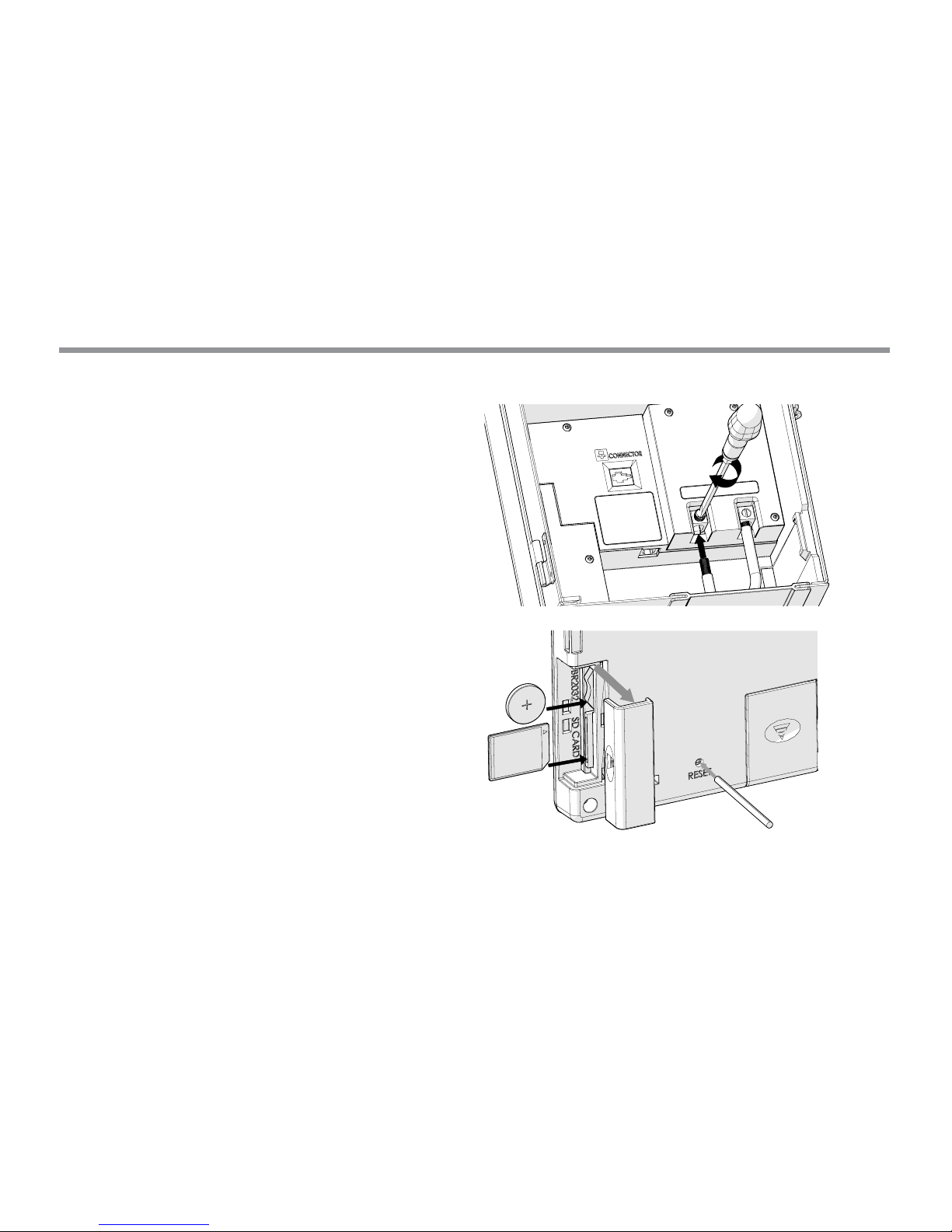
Back of facepack showing SD Card, Battery Door, and Reset Button
9
Operating the Luxor® ZD/ZDC
Navigating the Luxor
The Luxor contains only three user interface elements:
• HOME button: opens main screen while on any other function
• HELP button: displays text about the current page
• Clickable scroll wheel: primary interaction and selection tool
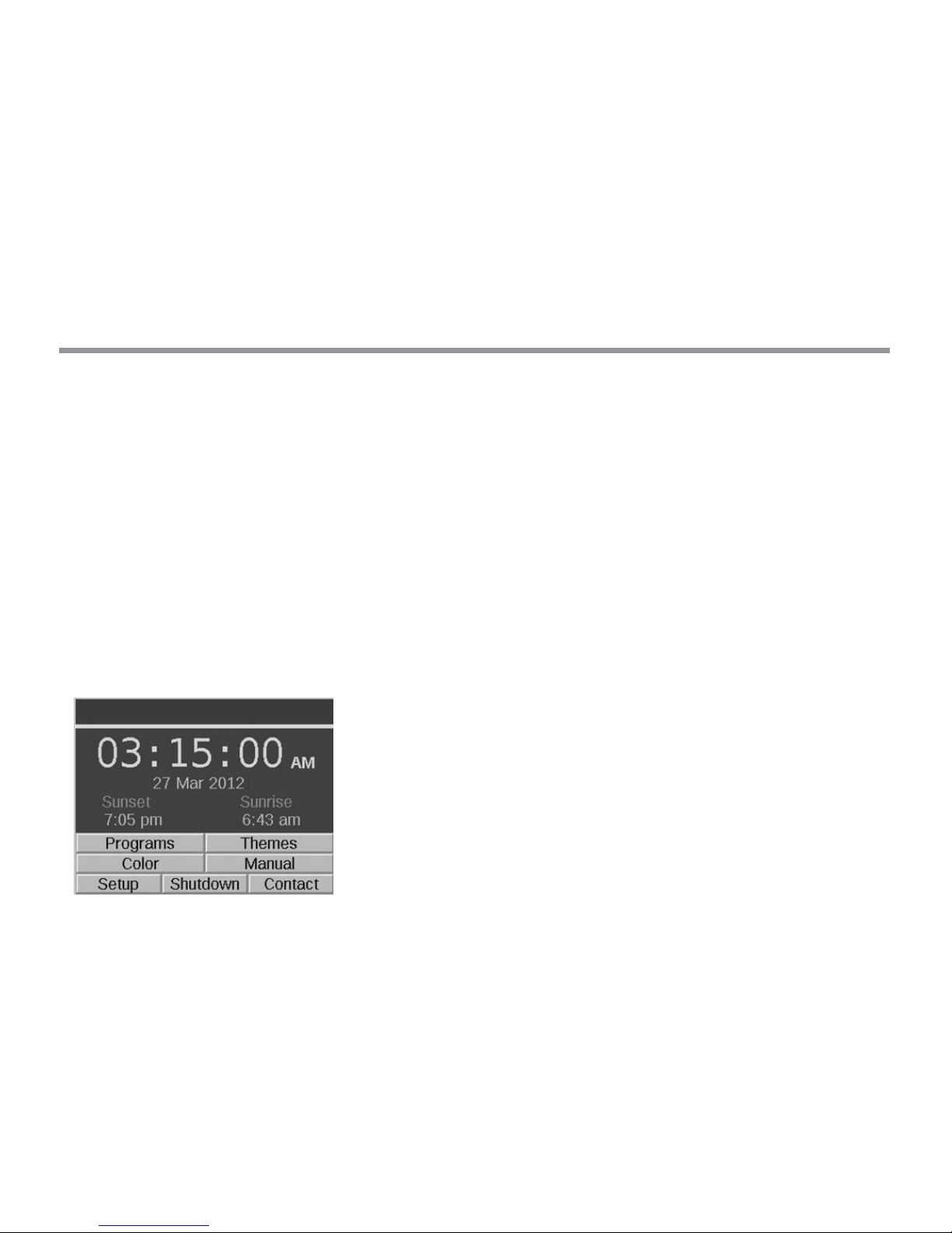
HOME Screen
All functions on the Luxor are accessible through the HOME screen.
The default display on the HOME screen includes the following:
• Current Time
• Current Date
• Sunrise/Sunset for the current day (dependent on location,
see SET LOCATION)
• All category options are listed
Figure 1: Home Screenshot
All category options are placed at the bottom of the HOME screen
and are selected using the main scroll wheel. Turn the gray scroll
wheel clockwise or counterclockwise until the desired category is
highlighted in orange. Press the scroll wheel inward to select and
enter the desired category.
• While in any screen, the HOME button can be pressed to return
to the HOME screen.
10
Operating the Luxor® ZD/ZDC
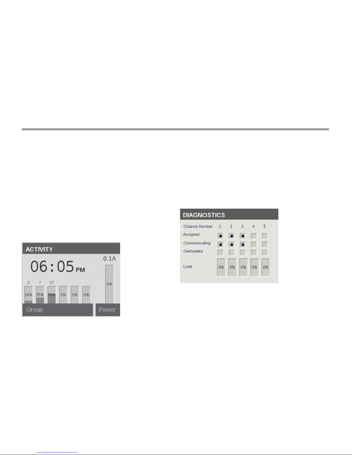
ACTIVITY Screen
Aer ve minutes of inactivity, an ACTIVITY screen will appear on the
LCD screen if the lights are running. The wait time is reduced to only
ve seconds when the current screen is the HOME screen.
The ACTIVITY screen displays:
• All currently running groups with their intensity level. Three
groups are shown in Figure 2, with a maximum of six groups
viewable at any given time. Turn the clickable scroll wheel to
show additional groups if more than six are in operation.
• Current Time
• System Load in Percent and Amps
No selections can be made on this screen; it is simply an activity
display. Press the HOME button to return to the HOME screen.
Figure 2: Activity Screenshot
DIAGNOSTICS Screen
Assigned
• Controller assigned
Communicating
• Controller communicating
Overload
• Controller overload indication
Load Status
• Controller load in percent
Figure 3: Diagnostics Screenshot
11
Operating the Luxor® ZD/ZDC
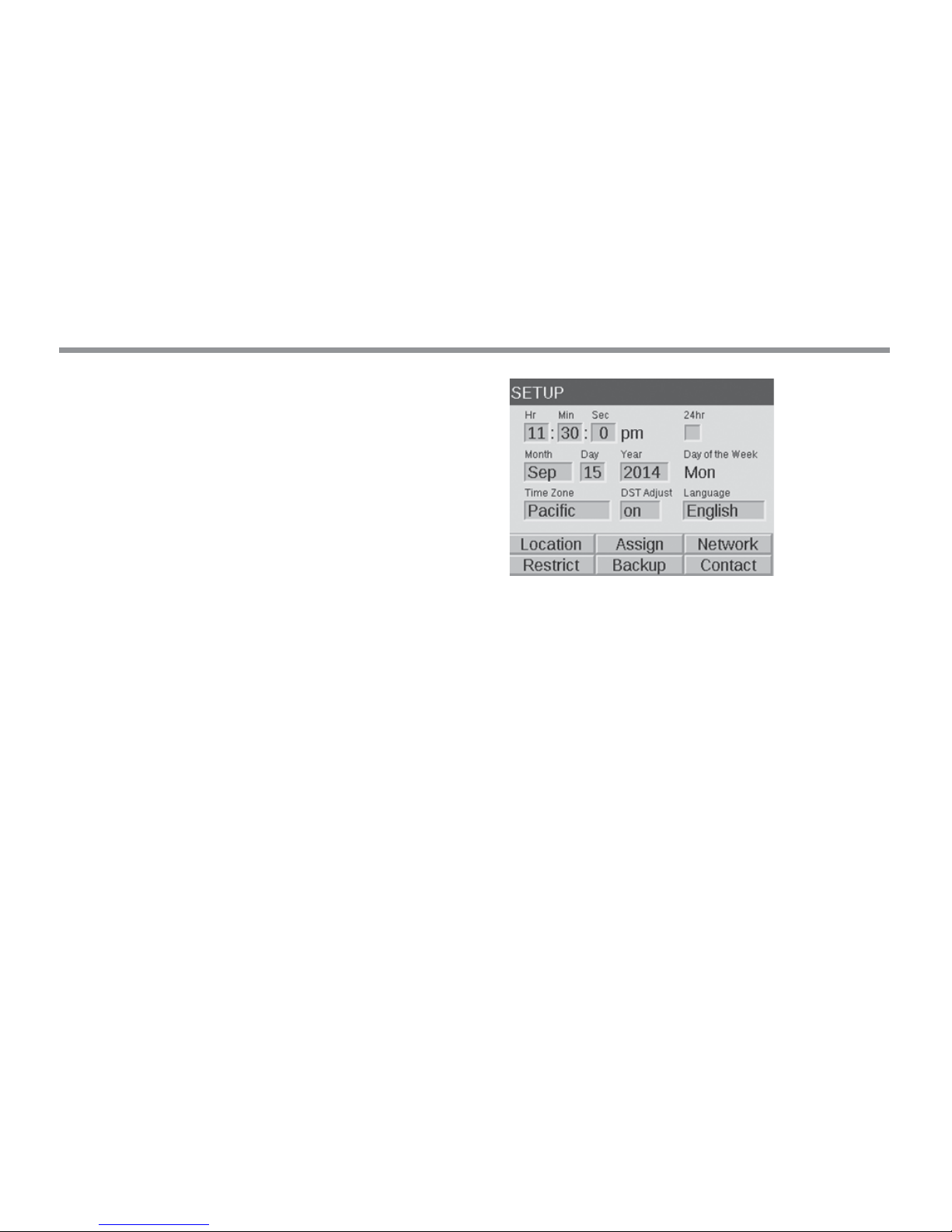
SETUP Screen
All background tools and settings (except color) are accessible
in the SETUP screen. Scroll through the various options to set up
the controller.
Time/Date
• Set the three time categories (Hr:Min:Sec) to the current time
settings by pushing the scroll wheel when the appropriate eld is
highlighted, scrolling through the numeric options, and pressing
the scroll wheel again to nalize the selection.
• Turn past 12 on the hour (“Hr”) setting to adjust AM and PM,
as displayed next to the seconds (“Sec”).
• To convert clock to 24-hour convention, select the “24 Hour”
selection box.
• Set the three date categories (Month, Day, Year) to the current
date by pushing the scroll wheel when the appropriate eld is
highlighted, scrolling through the options, and pressing the scroll
wheel again to nalize the selection.
• Setting the month, day and year automatically sets the day of the
week which appears to the right of the year.
• Daylight savings time (DST), when activated, will adjust time
forward or backward by 1 hour at the appropriate dates each year.
To initiate it, select ON. To deactivate it, select OFF.
Figure 4: Setup Screenshot

12
Operating the Luxor® ZD/ZDC
Language
In the SETUP screen, select the language eld by pressing the scroll
wheel and turning it to the desired language. Press the scroll wheel
again to nalize the selection.
• The language change will not take eect until either the HELP
or the HOME buttons are pressed.
Location
The LOCATION menu is designed to graphically represent a Luxor’s
location on a map for accurate Sunrise and Sunset times based on the
current date, time zone, and longitude/latitude settings.
First, set the time zone in the SETUP screen. While still in the SETUP
screen, enter the LOCATION screen to adjust longitude and latitude
coordinates.
• The full screen crosshairs designate the user’s location on
the map.
• Latitude is rst adjusted by rotating the scroll wheel to move the
crosshair up and down. Numeric indicators at the top right display
the actual coordinate. Press the scroll wheel to select the Latitude;
it is set by pressing the click-wheel.
• Longitude is next adjusted by rotating the scroll wheel to move the
crosshairs le and right.
• The coordinate settings are automatically saved aer each press
of the scroll wheel. Select the HOME button to leave the
LOCATION screen.
• Reset or adjustment is initiated by pressing the scroll wheel and
then repeating the above Latitude and Longitude steps.
Figure 5: Location Map of US
 Loading...