

Page 1
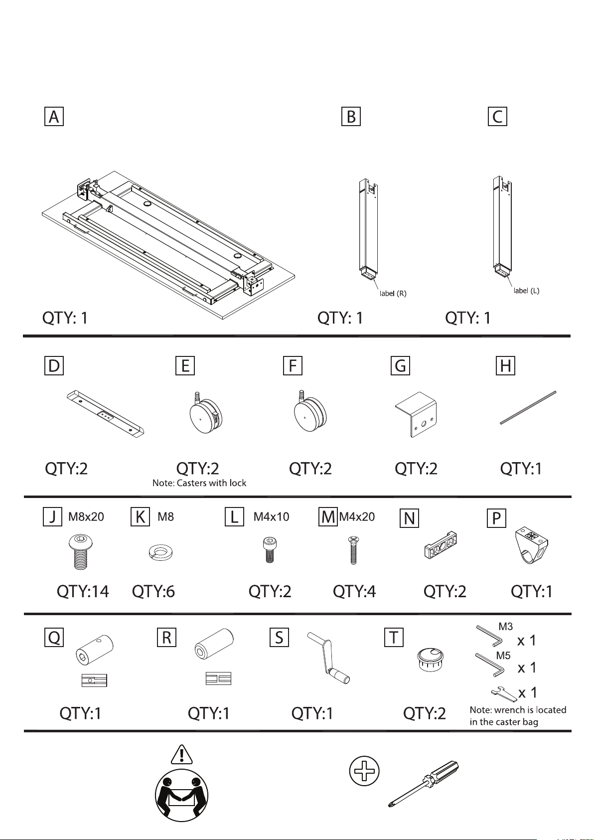
Height Adjustable Nesting Table Assembly Guide
Assistance Required
Screwdriver needed
Page 2
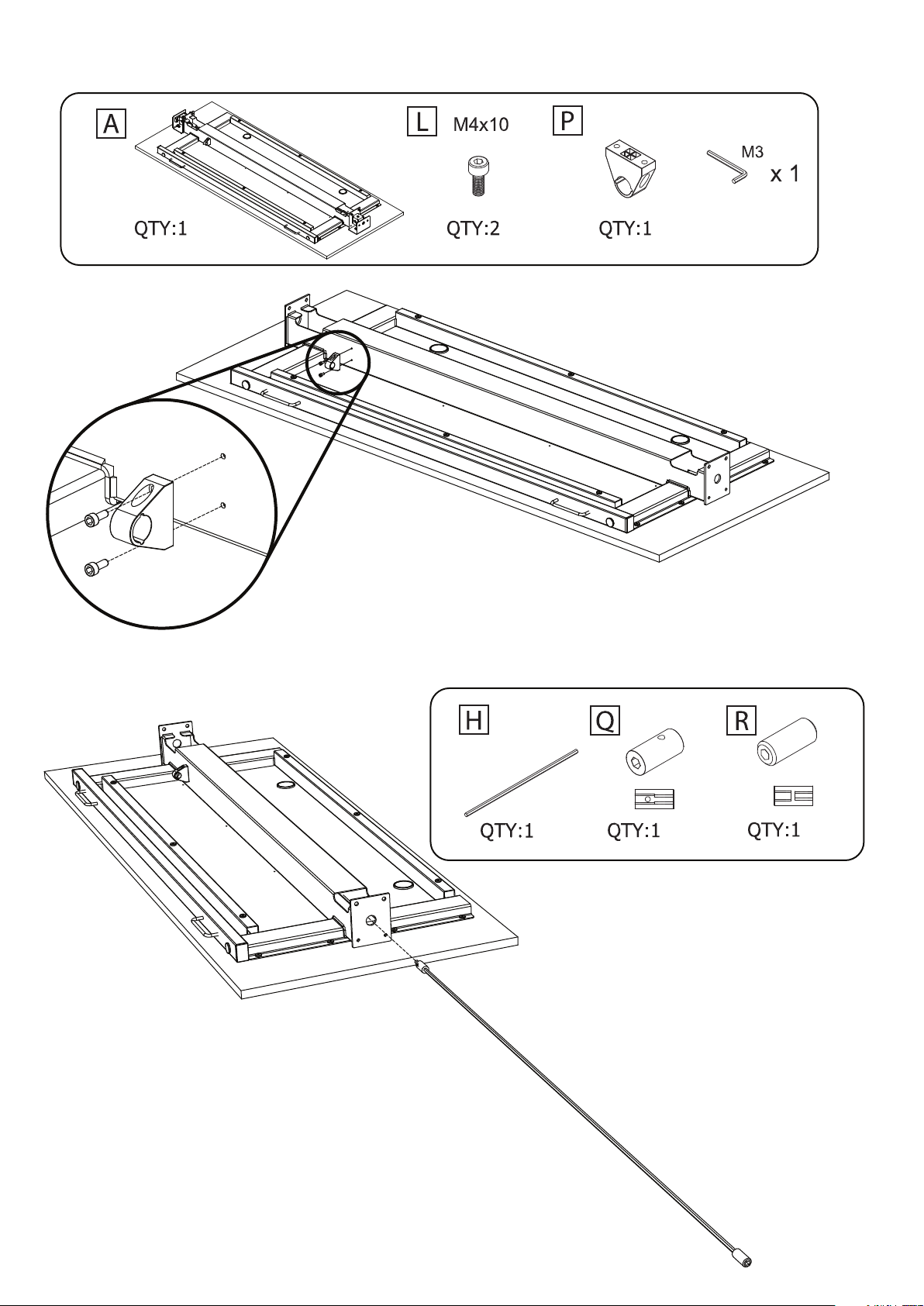
Step 1: Gather parts A, L, P, and the M3 hex wrench. Attach the crank handle holder to the top frame (A).
A
L
P
L
Step 2: Gather parts H, Q, and R. Place adapter parts (Q & R) onto the cross-rod (H). Slide the crossbar
into the top frame (A).
Q
Note: Part Q has a set screw that is used later.
H
R
Page 3

Step 3: Gather parts B, C, D, E, F, J,K,the M5 hex wrench, and caster wrench.
Attach the feet (E) to the legs (B & C) with 3 screws (1) per leg using the M5 hex wrench.
Attach the casters (E & F) to the feet, using the caster wrench.
F
D
K x 3
B
J x 3
E
F
K x 3
D
J x 3
E
C
Page 4

Step 4: Gather screws J, and the M5 hex wrench. Assistance is required in this step.
With assistance, and one side at a time, place and secure the leg assembles (B & C) to the top frame (A)
with 2 screws (J) per side, using the M5 hex wrench.
Part 1
B
4
C
A
Front
Part 2
J x 2
B
C
A
J x 2
Front
Page 5

Step 5: Gather the M3 hex wrench.
Part 1 - Slide the cross-rod (H) and adapter (R) onto the gear box on the leg (C).
Part 2 - Hold the cross rod (H) level with the gear box on the leg (B), and slide the
adapter (Q) on the gear box. Secure the adapter (Q) to the cross-rod (H) by tightening
the set screw with the M3 hex wrench.
B
Q
H
Front
A
C
Part 1
Part 2
R
H
H
Q
Page 6

Step 5: Assistance is required in this step.
Note: The legs are only partially attached to the top frame at this time.
Part 1 - Carefully rotate the table into the upright position.
Part 2 - Pull the handles on the front of the table, and ip up the top
Front
Handle
Handle
Front
Step 6: Assistance is required in this step.
Note: The legs are only partially attached to the top frame at this time.
Carefully rotate the desk into the upright position.
Page 7

Step 6: Gather screws (J) and the M5 hex wrench. Finish attaching legs (B & C) to the top frame (A)
with 2 screws (J) per side, using the M5 hex wrench.
6
J x 2
C
J x 2
B
Page 8

Step 7: Gather screws (M), the plastic spacers (N), and the metal brackets (G). You will need a
screwdriver for this step. Attach the metal brackets (G), and the plastic spacers (N) to the legs (B &C)
with 2 screws (M) per side, using a screwdriver.
Screwdriver needed
M x 2
G
N
C
M x 2
G
N
B
Page 9
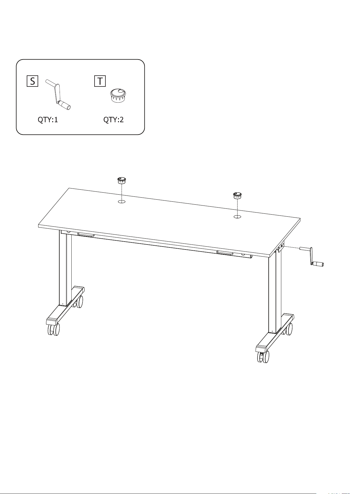
Step 6: Gather the crank handle (S) and the two grommets (T).
Insert the grommets (T) into the top (A). Insert the crank handle (S) into either leg (B or C).
Conrm all of the screws are secure.
You have completed assembly, and are ready to use the table.
T
T
C
A
S
B
 Loading...