

Luxor Riviera-66 Installation And Owner's Manual
1
PLEASE NOTE: This product has been manufactured using
steel and screws. As a result, there are many sharp edges
that can easily cut exposed skin. It is highly recommended
that you wear proper protective gloves while installing the
unit, and during routine cleaning or maintenance.
INSTALLER: Leave this manual with the customer
CUSTOMER: Retain this manual for future reference
©
--Do not store or use gasoline or other
Flammable vapors and liquids in the
vicinity of this or any other appliance.
--WHAT TO DO IF YOU SMELL GAS
• Do not try to light any appliance
• Do not touch any electrical switch; do
Not use any phone in your building;
• Immediately call your gas supplier from a
neighbor’s phone. Follow the gas
supplier’s instructions.
• If you cannot reach your gas supplier, call
The fire department.
-- Installation and service must be performed
By a qualified installer, service agency or
the gas supplier
WARNING: If the information in these
instructions is not followed exactly, a fire or
explosion may result causing property damage,
personal injury or death.
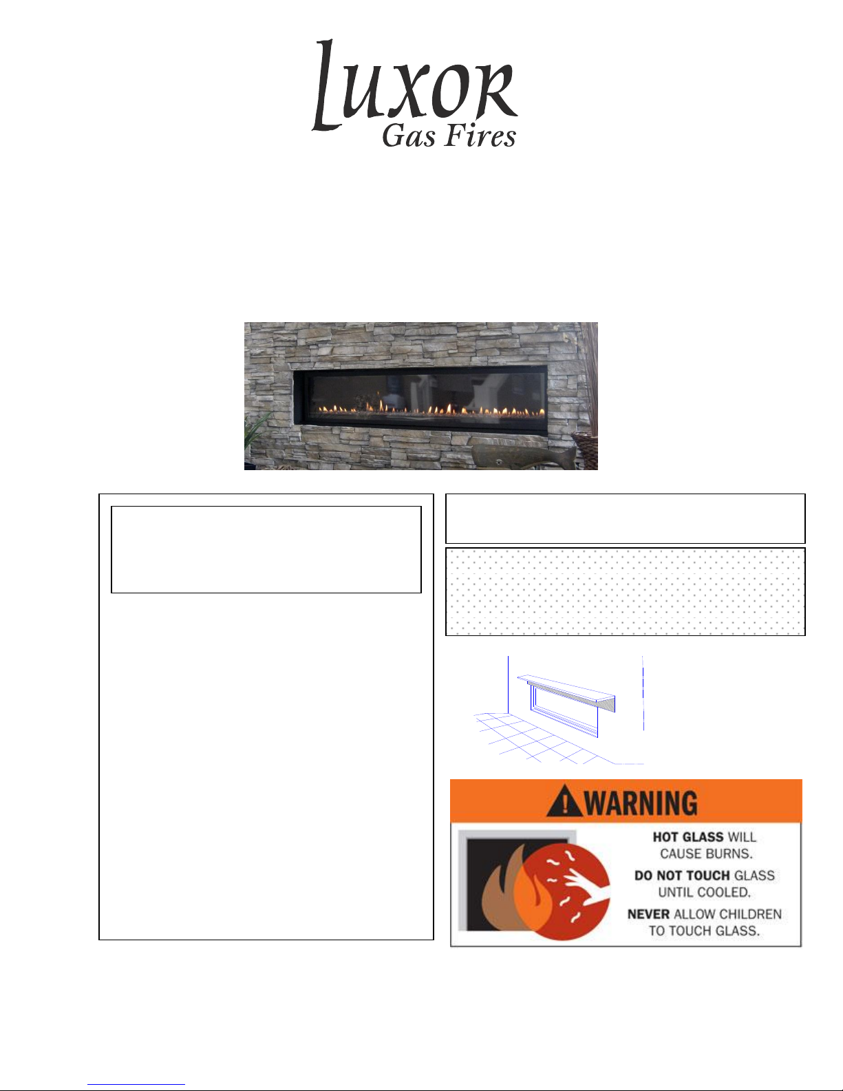
Direct Vent Gas Fireplaces
Model Riviera-66
Luxor Manufacturing Mfg.
#103-7075 Beatty Dr. Mission, B.C. Canada V2V-6C4
Installation and Owner’s Manual
.
.
2
Page 1…………………………………………………………………….. .....Cover Page with Safety Information
Page 2………………………………………………………………………….Table of Contents
Page 3 & 4…………………………………………………………………......Customer Greeting & Safety Information
Page 5 ………………………………………………………………………....Features and Specifications
Page 6……………………………………………………………………….....Framing Specifications
Page 7………………………………………………………………………… Placement and Mantel Requirements
Page. 8…………………………………………… …………………………....Corner Installation / Supply Lines Specs.
Page 9………………………………………………………………………….Venting Components
Page 10………………………………………………………………………... Vent Installation
Page 11…………………………………………………………………………Vertical Venting
Page 12…………………………………………………………………………Horizontal Venting
Page 13…………………………………………………………………………Exterior Vent Clearances
Page 14…………………………………………………………………………Installation Planning
Page 15…………………………………………………………………………Installing Non-Combustible Panels
Page 16 & 17…………………………………………………………………...Cleanface Mounting Instruction
Page 18…………………………………………………………………………Glass Door Removal/Re-attachment
Page 19………………………………………………………………………… Electrical
Page 20………………………………………………………………………….Lighting Instructions
Page 21………………………………………………………………………….Final Checks
Page 22………………………………………………………………………….Thermostat / Pilot Check
Page 23………………………………………………………………………….Flame Adjustment
Page 24………………………………………………………………………….Replacement Parts
Page 25………………………………………………………………………….Maintenance
Page 26………………………………………………………………………….Warranty
Table of Contents
3
CONGRATULATIONS
Welcome to Our Luxor Gas Fireplace Family
We hope you’ve had an easy and enjoyable time choosing from our line of products, and we certainly
appreciate your business. Please take some time to read through the following information, and make
sure to heed all of the warnings. Even though our fireplaces are easy to install and simple to operate,
they are still gas burning units with some inherent dangers if not careful
DO NOT: Use tools to operate controls. Use only your hand to push in and turn controls.
DO NOT: Abuse glass doors by striking or slamming shut.
DO NOT: Clean the appliance when hot.
DO NOT: Use this appliance if you smell gas.
DO NOT: Use this appliance if any part has been under water. Immediately call a qualified service technician to inspect
the appliance and replace any part of the control system and any gas control which has been under water.
General Safety (Home Owner)
•Fire Extinguisher: Every home should have at least on fire extinguisher. An approved Class A-B-C extinguisher should be
mounted on the wall near an exit and close to the application, but not so close that accessibility to the extinguisher could be
blocked by a fire. Your local Fire Department can advise you concerning the most appropriate location.
•Smoke Detectors & Carbon Monoxide Detectors on each floor of your home to ensure your safety. It should be located away
from the gas appliance and close to the sleeping areas. Follow the detector’s manufacturer’s placement installation and
maintenance instructions.
Safety for the installer
Wear gloves and safety glasses for protection.
Exercise extreme caution when using ladders or when
on roof tops.
Be aware of electrical wiring locations in walls and
ceilings.
Use a back support for heavy lifting.
Vent safety
Venting must be installed according to local codes.
Electrical code
When installed, these appliances must be electrically grounded
in accordance with local codes.
FOR YOUR SAFETY – Read before lighting
Installation and repair should be done by a qualified service person. The appliance should be
inspected before use and at least annually by a professional service person. More frequent
cleaning may be required due to excessive lint from carpet, bedding material, etcetera. It is
imperative that control compartments, burners and circulating air passageways of the appliance
be keep clean.
Date Purchased:_____________________________
Dealer:__________________________________________________________________
Installer:________________________________________________________________
Phone:_________________________________ Serial Number:____________________
4
This appliance is only for use with the Natural Gas as indicated on the rating plate.
Note: The copy in the manual is for reference only. In the event of a discrepancy, the label on the unit is to be
taken as the latest version.
GAS SUPPLY
ONLY PERSONS LICENSED TO WORK WITH GAS PIPING MAY MAKE THE NECESSARY GAS CONNECTION TO
THIS APPLIANCE. YOU ARE NOW READY TO HOOK UP THE GAS SUPPLY. BE SURE GAS PLUMBING
INSTRUCTIONS AND ALL PROVINCIAL AND LOCAL CODES ARE CAREFULLY FOLLOWED. USE APPROVED
FLEXIBLE GAS CONNECTIONS OR RIDGID PIPING, DEPENDING ON PROVINCIAL AND LOCAL CODES, TO
ATTACH BURNER TO GAS SUPPLY. BE SURE TO USE PROPER SIZE GAS SUPPLY LINE. CAREFULLY CHECK
ALL CONNECTIONS FOR GAS LEAKS WITH SOAP AND WATER SOLUTION.
EACH INSTALLATION MUST CONFORM TO ALL LOCAL, PROVINCIAL, AND NATIONAL CODES. REFER TO
THE NATIONAL FUEL GAS CODE, LOCAL ZONING AND CODE AUTHORITIES FOR DETAILS ON
INSTALLATION REQUIREMENTS.
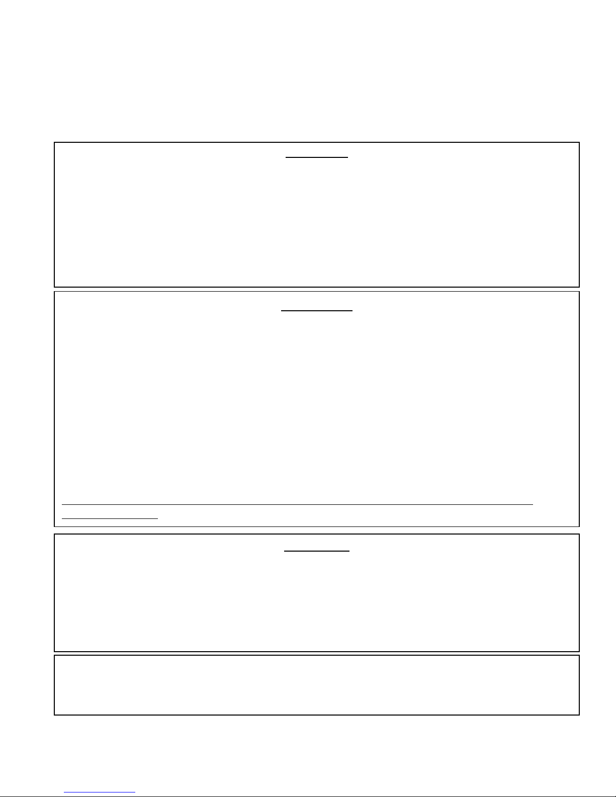
WARNING
DO NOT burn ANY materials in this fireplace.
All occupants of the home, especially children, should be alerted about the hazards of the high surface
temperature and the chance of severe burning or the possible ignition of clothing.
Young children should be carefully supervised when they are in the same room as the appliance.
Due to the high temperatures, the fireplace should be installed away from the furniture and draperies and
out of traffic areas.
Nothing should ever be placed on or near the surface of the fireplace, including the top of the unit.
Clothing or other flammable material should not be placed on or near the appliance.
Make certain the control panel, burners, fans, and venting system are kept clean. Inspection of these
systems should be inspected annually by a qualified service technician.
Any safety screen or guard removed for servicing the appliance must be replaced prior to operating the
appliance.
The fireplace, under NO circumstances, should ever be modified.
Do not operate the fireplace if damaged, or if the glass is cracked. Any repairs must be done by a
certified technician.
Certification
The Model Riviera-66 is listed and certified for installation in the U.S.A. and Canada under the
following standards:
ANSI Z21.88 (2009)/CSA 2.23.(2009)
The installation must conform with local codes or, in the absence of local codes, with the National Fuel
Gas and Propane Installation Code, ANSI Z223.1 / NFPA 54 in the US or the Natural Gas and Propane
Installation Code, CSA B149.1 in Canada.
Please contact Canadian Fire Hearth Manufacturing if you have any questions regarding the certification of this appliance.
A Manufactured home (USA only) or mobile home OEM installation must conform with the (U.S.) Manufactured Home
Construction and Safety Standard, Title 24 CFR, Part 3280, or , when such standard is not applicable, the Standard for Fire
Safety Criteria for Manufactured Home Installation Sites and Communities, ANSI/NFPA 501A, in the United States, or the
Mobile Homes Standard, CAN/CSAZ240 MH Series, in Canada
5
FEATURES AND SPECIFICATIONS
Note: Always check appliance label for correct information
The Luxor Riviera 66 is a direct vent gas
appliance utilizing an inclined vent for superior
installation flexibility. It enables either horizontal
or vertical vent installation without laboring to
convert over a dual type unit or having to
purchase a dedicated vent configuration.
MODEL: RIVIERA-66 Natural Gas
Manifold Pressure 3.5in w.c.
Min. Supply pressure 5.0in w.c.
Max Supply pressure 11in w.c.
Orifice size (x2) #42
Nominal input rating 46,000 BTU/hr
High altitude (US) 0-2000ft / 0-610m
High altitude (Canada) 0-4500ft / 0-1370m
Primary Air Opening
Electrical Rating 115 volts 0.7 amp 60hz
Circulating fan (optional) Variable Speed
Vent System Direct Vent
Glass Ceramic
HIGH ALTITUDE INSTALLATION
When installing this appliance beyond 2000ft (610M) above sea level, the appliance must be properly derated and
Installed according to local codes, in absence of local codes, with the current National Fuel Gas Code, ANSI
Z223.1/NFPA 54, in the US or Installation Code, CAN.CGA-B149, in Canada.
HIGH ALTITUDE INPUT DE-RATING
0-2000ft (0-610M): 46,000 BTU/hr (13.48kW)
2000ft (610M) and above: 46,000 BTU/hr (13.48kW) less 4% per 1000 ft. (305M)
Please Note: Only products supplied by the manufacturer may be used in the installation of this appliance.
6
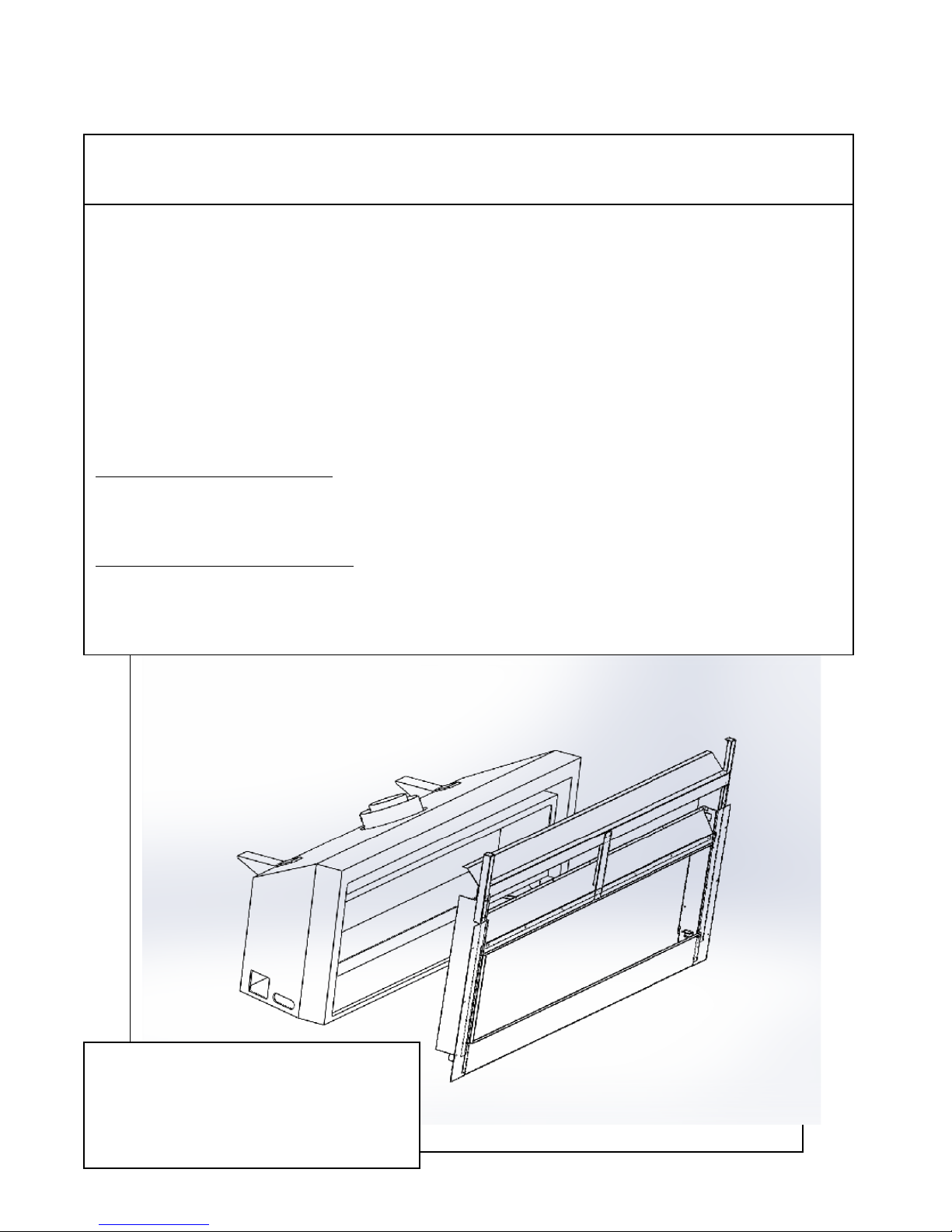
Installation
Note: To provide the easiest installation center the appliance between the vertical framing at the rear so the venting will be
centered. This will allow venting to pass through the framing without modifications.
Minimum Framing Dimensions
Framing the Rear Vent Opening at 14.25” square is necessary for required Wall Thimble. (Part # WTR58) NonCombustible panel (supplied by Luxor) must be installed on the top of the opening.
Non-combustible panel must be
fastened to the top of any
combustible framing.
Rear Venting Exit Minimum. Center vertical
framing with appliance
• Gas Inlet Location
6” from front by 3.5” above floor.
•Electrical connection is centered
10” from front at 3.5” from floor on
each side of the appliance
B
C
D
E
Minimum Clearances
A = Minimum Inside Height 79”
B = Header Height 35.5”
C = 69.5”
D = Minimum Depth 23”
E = Minimun Chase Width 87.5”
7
Mantel Requirements
No Combustible materials
are permitted lower than
8.5”(inches) above the
opening of the appliance
represented by the hatch
area. A projection ( mantel or
trim) of combustible material
can be no greater than 8”
(inches) at or below the 8.5”
(inches) height. This area is
indicated by the cross hatch
in the illustration.
Caution: any finish like
stains or clear coatings must
be of a high heat design to
prevent discolouration.
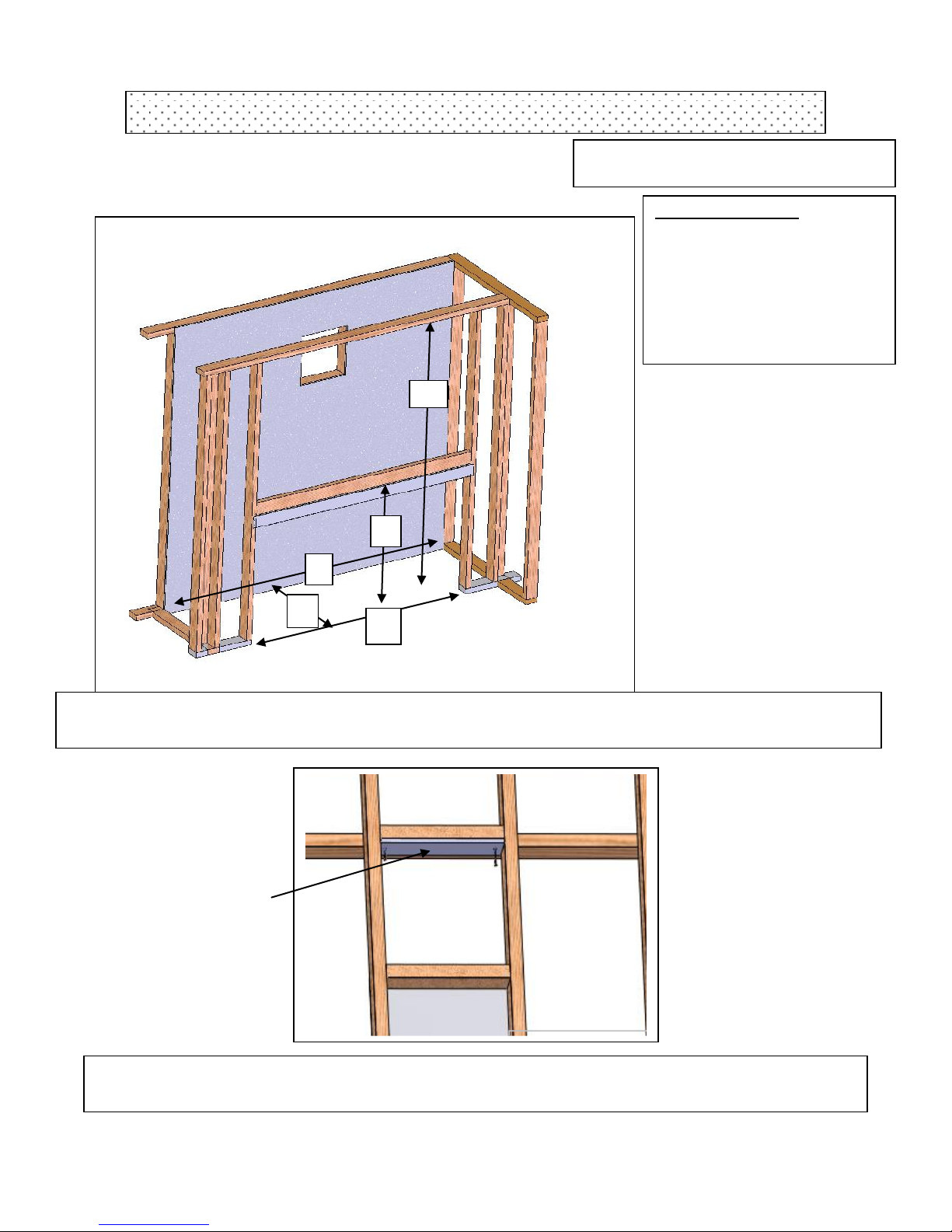
Placement of Appliance Non-Combustible Panels
The factory supplies
two non-combustible
panels that must be
secured in place before
the appliance can be
installed. The 66 1/4”
X 17 ¼” panel is
placed on the base
centered directly
beneath the unit as
shown (A). The 48” x
17” panel must be
secure to the back wall
of the chase so that the
top edge is in line with
the 14” x 14” open for
the venting as shown
(B)
B
A
8
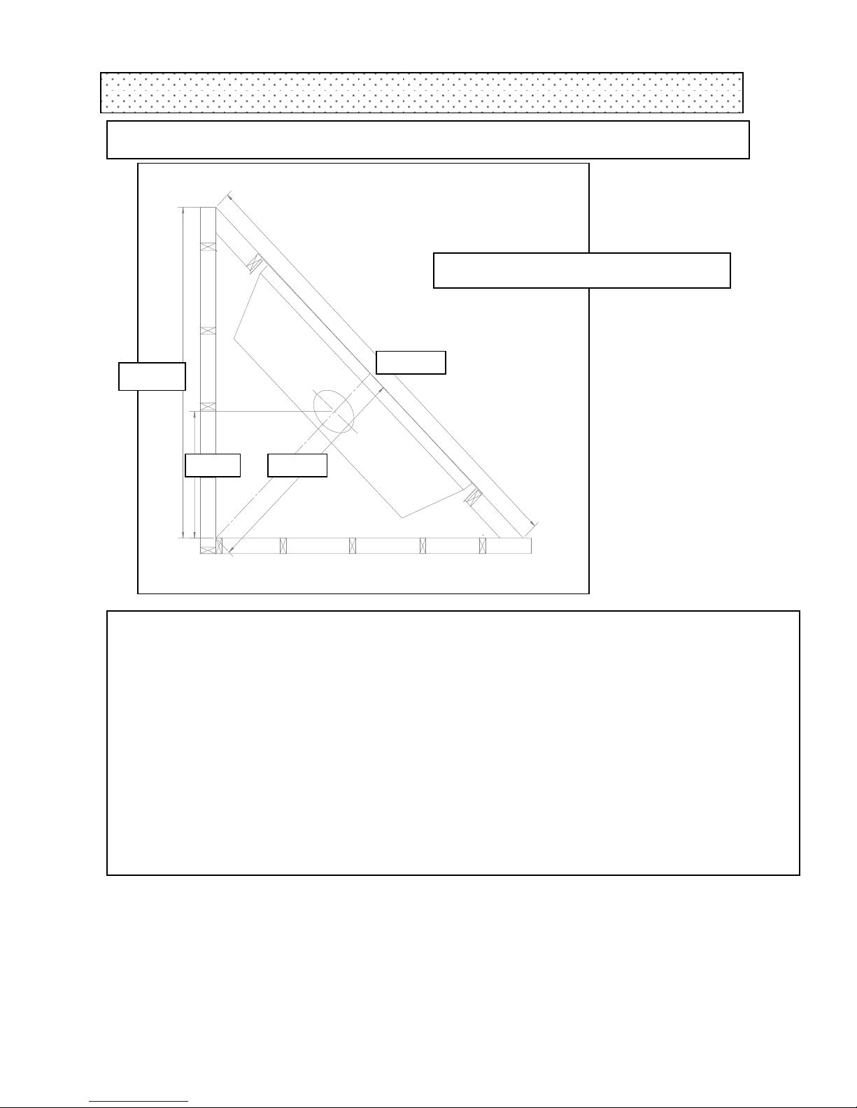
Corner Installation
A 45º angle installation
Installing Gas and Electrical Supply Lines.
Both Gas and Electrical lines must be installed and accessible for the installation of the Riviera 66.
Natural Gas requires a minimum inlet gas pressure of 5.0 in W.C.. Liquid Propane Fuel requires a
minimum of 11.0 in. W.C. IMPORTANT: Installer please allow a portion of the gas line
connecting to the appliance to be flexible enough for moving and aligning the appliance into the
chase. It’s very advisable to connect and secure gas lines before attaching the Cleanface Front.
After securing the Cleanface to the appliance access to the gas compartment becomes limited.
A grounded 117volt AC line must be supplied to the appliance and wired into the electrical box
which is fixed to the right hand side of the appliance. This will supply power to the AC Adapter
which powers the Electronic Valve System and also provides power for an optional electrical
blower if installed.
Framing and Clearance
Unit maybe installed in any location that maintains proper clearances to air conditioning ducts, electrical
wiring and plumbing. Safety, as well as efficiency of operation must be considered in selecting a fireplace
location. Select a location that does not interfere with room traffic, has adequate ventilation, and offers an
accessible pathway for venting installation.
102.00
51.0
72.5
27.7
Typical layout for a corner installation
 Loading...