

Page 1
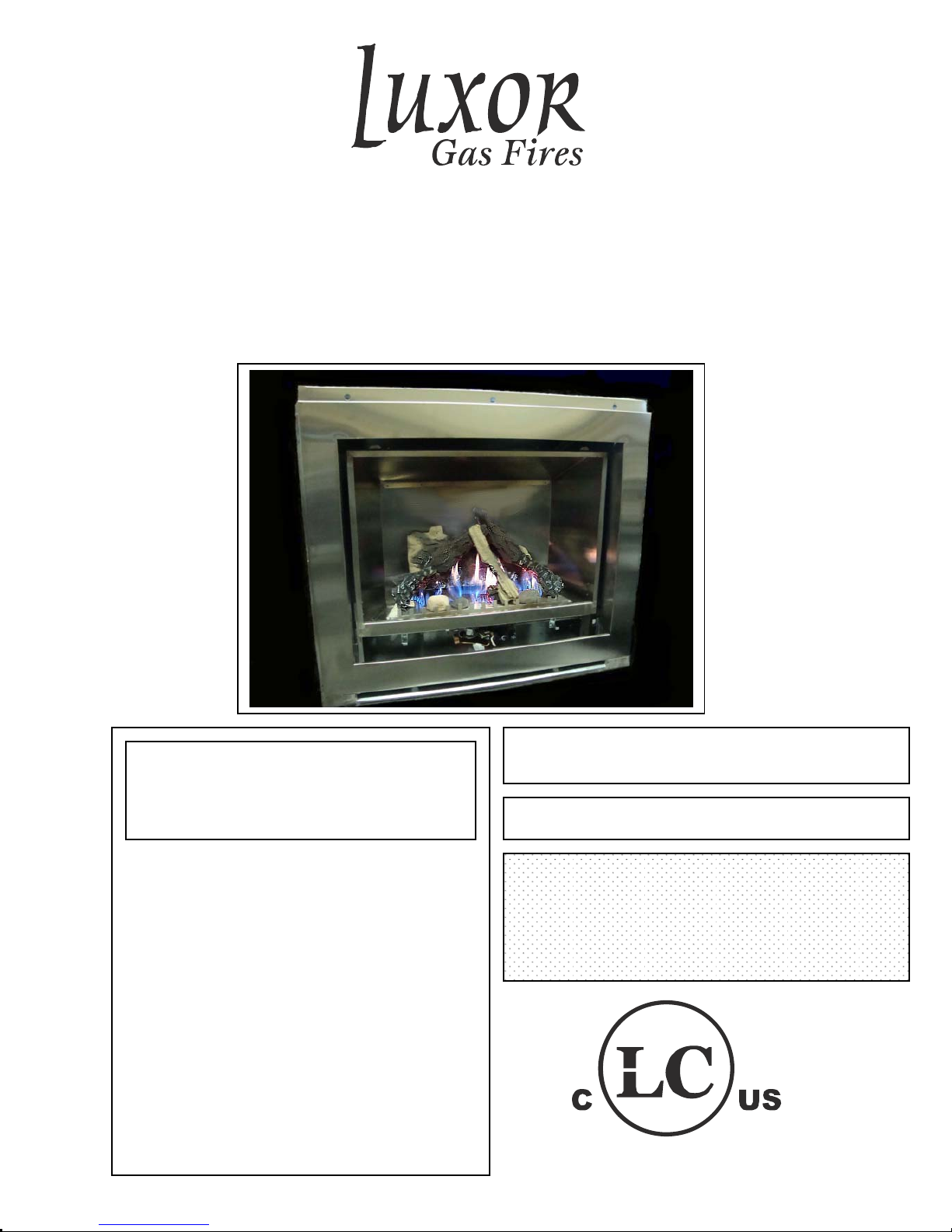
Stainless Steel Gas Fireplace
Installation and Owner’s Manual
Outdoor Ventless
Model MBO-36
Canadian Fire Hearth Mfg
7075-Beatty Drive, Mission B.C. V2V-6C4
.
WARNING: If the information in these
.
instructions is not followed exactly, a fire or
explosion may result causing property
damage, personal injury or death.
--Do not store or use gasoline or other
flammable vapors and liquids in the
vicinity of this or any other appliance.
--WHAT TO DO IF YOU SMELL GAS
• Do not try to light any appliance
• Do not touch any electrical switch; do
not use any phone in your building;
• Immediately call your gas supplier from a
neighbor’s phone. Follow the gas
supplier’s instructions.
• If you cannot reach your gas supplier, call
the fire department.
-- Installation and service must be performed
by a qualified installer, service agency or
the gas supplier.
INSTALLER: Leave this manual with the customer
CUSTOMER
FOR OUTDOOR INSTALLATION ONLY
PLEASE NOTE: This product has been manufactured
using steel and screws. As a result, there are many
sharp edges that can easily cut exposed skin. It is
highly recommended that you wear proper protective
gloves while installing the unit, and during routine
cleaning or maintenance.
: Retain this manual for future reference
1
Page 2
Table of Contents
Page 1……………………………………………………….Cover Page with Safety Information
Page 2……………………………………………………….Table of Contents
Page 3 & 4…………………………………………………..Customer Greeting & Safety Information
Page 5 ………………………………………………………Features and Specifications
Page 6……………………………………………………….Framing Specifications
Page 7……………………………………………………… Finishing/Mantel Allowances
Page. 8…………………………………………… …………Installation
Page 9……………………………………………………….Installation cont.
Page 10………………………………………………………Clearance Specifications
Page 11………………………………………………………Lighting Instructions
Page 12………………………………………………………Thermostat
Page 13………………………………………………………Log Set Installation
Page 14………………………………………………………Log Set Installation cont.
Page 15………………………………………………………Log Set Installation cont.
Page 16 ……………………………………………………..Flame Quality
Page 17………………………………………………………Replacement Parts
Page 18………………………………………………………Final Checks
Page 19………………………………………………………Warranty
WARNING!
•FOR OUTDOOR USE ONLY. This appliance can only be installed in a well-vented space
and shall NOT be used inside a building, garage, or any other enclosed area.
•DO NOT LEAVE FIREPLACE UNATTENDED WHEN IN USE.
•THIS APPLIANCE MUST NOT BE USED FOR COOKING.
•THIS APPLIANCE IS NOT FOR USE WITH SOLID FUEL.
•DO NOT ALLOW WIND TO BLOW DIRECTLY INTO THE APPLIANCE. Avoid any strong
drafts that alter the flame pattern.
•DO NOT ALLOW HEAVY RAIN FALL DIRECTLY INTO APPLIANCE. Although this unit
meets certification standards for outdoor appliances it maybe installed unsheltered and
exposed directly to many weather conditions. Avoid any prolonged heavy rain exposure
directly into the firebox. Use the optional cover when extended shutdown periods are
anticipated
2
Page 3
CONGRATULATIONS
–
We hope you’ve had an easy and enjoyable time choosing from our line of products, and we certainly
appreciate your business. Please take some time to read through the following information, and make
sure to heed all of the warnings. Even though our fireplaces are easy to install and simple to operate,
they are still gas burning units with some inherent dangers if not careful
Date Purchased:_____________________________
Dealer:__________________________________________________________________
Installer:________________________________________________________________
Phone:_________________________________ Serial Number:____________________
FOR YOUR SAFETY
DO NOT: Use tools to operate controls. Use only your hand to push in and turn controls.
DO NOT: Clean the appliance when hot.
DO NOT: Use this appliance if you smell gas.
DO NOT: Use this appliance if any part has been under water. Immediately call a qualified service technician to
inspect the appliance and replace any part of the control system and any gas control whi ch h as been under water.
General Safety (Home Owner)
•Fire Extinguisher: Every home should have at least on fire extinguisher. An approved Class A-B-C extinguisher should be
mounted on the wall near an exit and close to the application, but not so close that accessibility to the extinguisher cou ld be
blocked by a fire. Your local Fire Department can advise you concerning the most appro priate location.
•Smoke Detectors & Carbon Monoxide Detectors on each floor of your home to ensure your safety. It should be located away
from the gas appliance and close to the sleeping areas. Follow the detector’s manufacturer’s plac ement installation and
maintenance instructions.
Safety for the installer
Wear gloves and safety glasses for protection.
Be aware of electrical wiring locations in walls and
ceilings.
Use a back support for heavy lifting.
Installation and repair should be done by a qualified service person. The appliance
should be inspected before use and at least annually by a professional service person.
More frequent cleaning may be required due to excessive lint from carpet, bedding
material, etcetera. It is imperative that control compartments, burners and circulating
air passageways of the appliance be keep clean.
Welcome to Our Luxor Gas Fireplace Family
Read before lighting
Carbon Monoxide Poisoning: Early signs of carbon monoxide
poisoning are similar to the flu with headaches, dizziness and/or
nausea. If you have these signs, obtain fresh air immediately.
3
Page 4
This appliance is only for use with Natural Gas as indicated on the rating plate.
Q
Note: The copy in the manual is for reference only. In the event of a discrepancy, the label on the
unit is to be taken as the latest version.
ONLY PERSONS LICENSED TO WORK WITH GAS PIPING MAY MAKE THE NECESSARY GAS CONNECTION
TO THIS APPLIANCE. YOU ARE NOW READY TO HOOK UP THE GAS SUPPLY. BE SURE GAS PLUMBING
INSTRUCTIONS AND ALL PROVINCIAL AND LOCAL CODES ARE CAREFULLY FOLLOWED. USE APPROVED
FLEXIBLE GAS CONNECTIONS OR RIDGID PIPING, DEPENDING ON PROVINCIAL AND LOCAL CODES, TO
ATTACH BURNER TO GAS SUPPLY. BE SURE TO USE PROPER SIZE GAS SUPPLY LINE. CAREFULLY
CHECK ALL CONNECTIONS FOR GAS LEAKS WITH SOAP AND WATER SOLUTION.
EACH INSTALLATION MUST CONFORM TO ALL LOCAL, PROVINCIAL, AND NATIONAL CODES. REFER TO
THE NATIONAL FUEL GAS CODE, LOCAL ZONING AND CODE AUTHORITIES FOR DETAILS ON
INSTALLATION RE
UIREMENTS.
GAS SUPPLY
DO NOT burn ANY materials in this fireplace.
All occupants of the home, especially children, should be alerted about the hazards of the high surface
temperature and the chance of severe burning or the possible ignition of clothing.
Young children should be carefully supervised when they are in the same room as the appliance.
Due to the high temperatures, the fireplace should be installed away from traffic areas.
Nothing should ever be placed on or near the surface of the fireplace, including the top of the unit.
Clothing or other flammable material should not be placed on or near the appliance.
Make certain the control panel, burner are kept clean. Inspection of these systems should be inspected
annually by a qualified service technician.
Any safety screen or guard removed for servicing the appliance must be replaced prior to operating the
appliance.
The fireplace, under NO circumstances, should ever be modified.
Do not alter gas orifice
Do not operate the fireplace if damaged. Any repairs must be done by a certified technician.
WARNING
The Model MBO-36 is listed and certified for installation in the U.S.A. and Canada under the
The installation must conform with local codes or, in the absence of local codes, with the
National Fuel Gas and Propane Installation Code, ANSI Z223.1 / NFPA 54 in the US or the
Please contact Canadian Fire Hearth Manufacturing if you have any questions regarding the certification of this appliance.
Natural Gas and Propane Installation Code, CSA B149.1 in Canada.
ANSI Z21.97 2010/CR97-003.
Certification
following standards:
4
Page 5
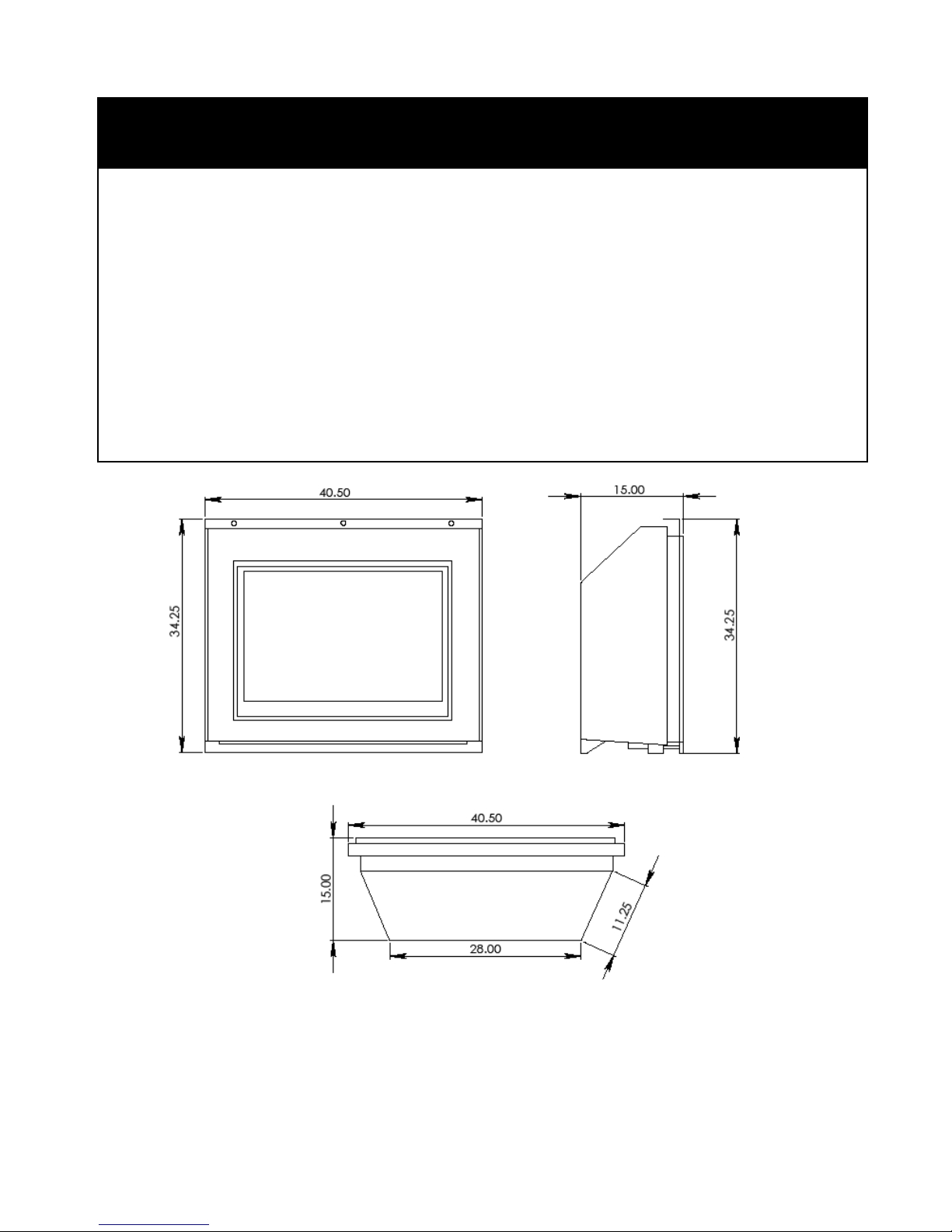
FEATURES AND SPECIFICATIONS
Note: Always check appliance label for correct information
MODEL: MBO36 Natural Gas
Manifold Pressure 3.5in. w.c.
Min. Supply pressure 5.5in. w.c.
for purpose of input adjustment
Max Supply pressure 11in. w.c.
Orifice size #35
Nominal input rating 35000 BTU/hr
High altitude (US) 0-2000ft / 0-610m
High altitude (Canada) 0-4500ft / 0-1370m
Primary Air Opening
Vent System Ventless
Clean Face Kit (factory installed on all units) 304 Stainless Steel
Please Note: Only products supplied by the manufacturer may be used in the installation of this appliance.
5
Page 6
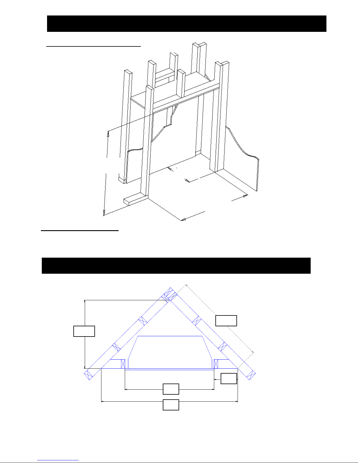
Installation
Minimum Framing Dimensions
Framing and Clearance
Unit maybe installed in any location that maintains proper clearances to air conditioning ducts, electrical
wiring and plumbing. Safety, as well as efficiency of operation must be considered in selecting a fireplace
location. Select a location that does not interfere with foot traffic has adequate air movement.
.
30.5
3.42
35
16.75
38
Corner Installation
4.46
41
6.84
60
4
.
8
41.5
2
1.19
10
6
Page 7

Finishing and Facing Material Considerations
Sliding drain tray
No combustible materials
can extend past this line
In order to adequately drain the
appliance a sliding drain tray is built
into the lower section of the unit. In an
application where the existing stainless
face will be featured, the tray can
remain in the inner most position. If a
non-combustible material like stone or
brick is to be added over the facing the
drain tray must not be covered. Doing
so will prevent proper water drainage.
The tray can be pulled out to match the
thickness of any desired material.
Mantel Requirements
Framing
The attached chart represents the maximum allowable
mantel or shelf limits using combustible materials determined
by in the certification guidelines. Due to the wide range of
designs and materials of non-combustible mantels, shelves,
and overlays caution must be exercised when choosing to
finish this appliance. Any such installations must conform to
local codes. For any further information contact CFH Mfg.
framing
Fireplace Cleanface
Top edge of
fireplace opening
Side wall
1.5”
The MBO-36 is shipped with non-combustible panels which must be installed with the appliance
to conform with to certified safety standards. the panel is secured above the Cleanface
Mantel/Surround Side clearance
7
Page 8

Placements of Non-combustible Panels
In any installation in which the unit is installed into a chase constructed of combustible materials ie:
plywood, wood framing, convention wall board (including “waterproof” type) a certified non-combustible
½ in thickness or greater board must be installed in the designated areas. PLEASE NOTE: It is
mandatory that all supplied non-combustible panels be installed. Failure to do so could result in damage
to adjacent materials and/or fire.
Enclosure space around and above
the appliance must be left free of any
obstruction.
non-combustible
29.5” x 4” x 0.5”
34.5
Combustible
Non-combustible
36 x 4 x 0.5”
This wall can either be
inside or outside wall
3.82
Non-Combustible
sheet material
14” x 28” x 0.5”
1.70
17
NOTE: All non-combustible boards provided by the manufacturer.
8
Page 9

The recommended order of installation is as follows:
1 – Familiarize yourself with this manual.
2 – Check the minimum installation dimensions.
3 – Check your local installation codes.
4 – Check you have the parts and components necessary to complete the installation.
5 – Check the gas and electrical supplies are ready.
6 – Prepare opening (remove any loose materials)
7 – Install base unit.
8 – Connect gas.
9 – Install operational components and prepared for first test fire.
10 – Check to verify adequate accessibility clearance for service & proper operation.
11 – Check operation of unit.
12 – Take time to explain operation to customer (most call backs are caused by the customer not understanding the operatio n
of the unit.)
Installation Planning
Installing Gas and Electrical Supply Lines.
S
Gas and lines must be installed and accessible for the installation of the MBO-36.
Natural Gas requires a minimum inlet gas pressure of 5.5 in W.C.. IMPORTANT: Installer please allow a portion of
the gas line connecting to the appliance to be flexible enough for moving and aligning the appliance into the
chase.
Before interrupting the existing gas supply it is recommended that the following be checked.
Shut down all gas appliances and carry out a pressure test to ensure there are no leaks in the system.
Before connecting the appliance to the gas supply line, double check that the appli ance you have purchased is designed for the
gas type you are using. The gas type markings are located on the certification label and also on the appliance’s gas valve.
Check the gas pressure immediately upstream to ensure you will be able to supply the minimum inlet pressure for the
appliance.
Check your pipe sizing to ensure sufficient volume will be supplied to the appliance.
Existing Gas Supply
Provide adequate clearance for the proper installation and c hecking of the gas connection.
Have your gas supplier or a qualified gas fitter run a gas supply line into th e gas fireplace. The line must be properly sized and
fitted according to the installation codes. Upstream of the appliance supply connection, the fitter shall provide an easil y
accessible manual shut-off valve.
The gas supply pipe should enter the appliance case through the opening at the right sid e. T he supply pipe should be
connected to the appliance gas inlet pipe situated at the right side of the control unit. Supply line connection to the inlet pipe is
3/8 NPT.
Use only new black iron or steel pipes or copper tubing if acceptable – check local codes.
Note that in the USA copper tubing must be internally tinned for protection against sulfur compounds.
Unions in gas should be of ground joint type. Sealant used must be resistant to the action of all gas constituents including LP
gas. Sealant should be applied lightly to male threads to ensure excess sealant does not enter gas lines.
Gas Supply Installation
9
Page 10

Clearance Specifications
D
FP
A
G
H
P
FP
G
FP
Q
J
or
X
K
FP
FP
B
B
C
FP
FP
F
FP
A
B
I
M
L
= fireplace opening X
FP
A = 2in. clearance above grade I = 3ft. (USA) clearance to service regulator
veranda, porch, deck or 6ft.(Canada) vent outlet and electrical service.
balcony
B = 12in. clearances to wind ow or door J = 9in. (USA) clearance to non-mechanical air
that may to opened, or to 12in.(Canada) supply inlet to building or the
permanently closed window. combustion air inlet to any other
36in. vinyl windows or siding. appliance.
C = 72in. clearance below an K = 3ft .(USA) clearance to a mechanical air
operable window. 6ft.(Canada) supply inlet.
D = 47in. vertical clearance to unventi- L*= 54in. clearance above paved sidewalk or
located above the fireplace. public property.(see note 1)
60in. vinyl clad soffits. M**= 47in. clearance under veranda,porch,deck
G = 4in. Clearance to inside corner balcon y or ove r hang
48in. Vinyl window or siding Not Allowed Vinyl
H = 36in.(Canada)Not to be installed above a gas P = 92in. see note 2) .
meter/regulator assembly within 3ft. Q = 72in.
horizontally from the center line of the
regulator.
lated or a ventilated soffit a paved drive way located on
= air supply inlet
= area where fireplace is not permitted
* A fireplace shall not open directly above a sidewalk or paved 3)All gravity air intakes within 3 ft of the fireplace must be
driveway which is located between two single family dwellings a minimum of 1 ft below the face top opening.
and service both dwellings. This fireplace is approved for installation in screened
**Only permitted if veranda, porch, deck or balcony is fully open porches with the following:
on a minimum of 2 sides beneath the floor, or if the screened Minimum porch area – 96 sq ft
porch guidelines are followed. Minimum ceiling height – 92 in.
Minimum of two walls must be screened or open
Note 1: Local codes or regulations may require different clearances Minimum top of screen height, side walls 6ft 8in.
Note 2: Fireplaces in an alcove space (spaces open on one side and Minimum screen area – 64 sq ft
with an overhang) are permitted with the dimensions Notes: There may be some odor and small amount of soot
specified for vinyl or non-vinyl siding and soffits. 1) There associated with burning the fireplace in a screened porch.
must be a 3 ft minimum between terminations or between Ensuring good cross draft ventilations and routine maintenance
the fireplace and termination. 2) All mechanical air intakes of the routine maintenance of the fireplace will maximize
within 10 ft of the top of the fireplace opening must be a comfort and cleanliness.
minimum of 3 ft below the top of the fireplace opening.
Lighting Instructions
10
Page 11

For your safety, read the following before lighting:
WARNING: If you do not follow these instructions exactly, a fire or explosion may
result causing property damage and personal injury or death.
A. This appliance has a pilot which must be lighted by hand.
When lighting the pilot, follow these instructions exactly.
B.
BEFORE LIGHTING smell all around the appliance
area for gas. Be sure to smell next to the floor because
some gas is heavier than air and will settle on the floor.
WHAT TO DO IF YOU SMELL GAS - Do not
try to light any appliance. - Do not touch any electric
switch; do not use any phone in your building. -
Immediately call your gas supplier from a neighbour’s
phone. Follow the gas supplier’s instructions. - If you
cannot reach your gas supplier, call the fire department.
Lighting Instructions
1. STOP! Read the safety information above on
this label.
2. Set the thermostat to lowest setting.
3. Tu rn off all electrical power to the appliance.
4. Remove louvers.
5. Pu sh in gas control knob slightly and turn
clockwise to “OFF”. Note: knob cannot be
turned from “PILOT” to “OFF” unless knob is
pushed in slightly. Do not force.
6. Wait five minutes to clear out any gas. Then
smell for gas, including near the floor. If you
smell gas, STOP! Follow “B” in the safety
information on this label. If you don’t smell gas
go on to the next step.
7. Turn knob on gas control counterclockwise to
“PILOT”
C. Use only your hand to push in or turn the gas or control
knob. Never use tools. If the knob will not push in or
turn by hand, don’t try to repair it, call a qualified service
technician. Force or attempted repair may result in a fire
or explosion.
D. Do not use this appliance if any part has been under
water. Immediately call a qualified service technician to
inspect the appliance and replace any part of the control
system and any gas control which has been under water.
8. Pu sh in control knob all the way and hold in.
Immediately push in piezo ignition button.
Continue to hold the control knob in for about
one minute after the pilot is lit. Release knob
and it will pop back up. Pilot should remain lit.
If it goes out, repeat steps five through eight. –
If knob does not pop up when released, stop and
immediately call your service technician or gas
supplier. – If the pilot will not stay lit after
several tries, turn the gas control knob to “OFF”
and call your service technician or gas supplier.
9. Tu rn gas control knob counterclockwise to
“ON.”
10. Replace louvers panel.
11. Turn on all electrical power to the appliance.
12. Set the thermostat to desired setting.
To Turn Off Gas to the Appliance
1. Set the thermostat to lowest setting.
2. Tu rn off all electrical power to the appliance if
service is to be performed.
3. Remove louvers.
SIT NOVA 820
Gas Valve
4. Pu sh in gas control knob slightly and turn
clockwise to “OFF”. Do not force.
5. Replace louvers.
11
Page 12

Thermostat Installation (not allowed in US installations)
The burner control switch is located in the centre of the control department opening. For your convenience, the unit can
also be operated by a thermostat or a wall switch control. Electronic are available from any authorized CFHMfg dealer.
Please note, bedroom installations require the use of a wall thermostat. Mount the thermostat or switch in the desired
location and run “two conductor thermostat wires” to the heater’s lower right hand corner, close to the gas supply line.
For maintenance, proper re-assembly and resealing of the venting system is required.
The appliance should be inspected before use and at least annually by a professional service
person.
More frequent cleaning may be required due to excessive lint from carpet bedding material etc. It is imperative
that control compartment, covers of the appliance to be kept clean.
The appliance and its individual shut-off valve must be disconnected from the gas supply piping system during any pressure
testing of the system at test pressures in excess of ½ psig (3.4kPa). The appliance must be isolated from the gas supply piping
system by closing its individual manual shut-off valve during any pressure testing of the gas supply piping system at test
pressures equal to or less than ½ psig (3.5kPa). Failure to do so will damage the appliance’s gas valve. Such damage is not
covered by the manufacturer’s warranty.
When testing for leaks:
Make sure that the appliance is turned off.
Open the manual shut-off valve.
Test for leaks by applying a liquid detergent or soap solution to all ball joints. Bubbles forming indicate a gas leak.
Correct any leak detected immediately.
Never use an open flame to check for leaks.
The pressure test point locations are built in to the regulator that controls the burner manifold pressure. The correct pressure
range is shown in the table in the specification section of this manual. The pressure check should be made with the burner lit.
See lighting instruction section for full operating details.
Note: The wall switch MUST be rated for electronic
Minimize splicing
in all wiring and solder all unavoidable splices.
Thermostat Wire Information
AWG mm ft. m
22 0.6 10 3.0
20 0.8 25 7.6
18 1.0 40 12.2
16 1.3 64 19.5
1.6 100 30.5 14
wall switch installation
Pressure testing the supply line for leaks
12
Page 13

MB0-36 Outdoor Gas Log Set
5
6
1
3
2
4
Log set up
Place the largest log on the log support
shelf located on the rear panel above the
air inlet. A small tab folded up from the
shelf is provided to secure to log in
position. Push the logs down onto the shelf
so that the tab forces into the logs. Use
sufficient force only to push the tab into the
log material. The log’s material is fragile
and excessive force will seriously damage
the log and would need to
be replaced
13
Page 14

Logs #2 and #3 join together at the tops so that the pin inserts into the
corresponding hole as shown in the insert.. Support the lower end of
Place log #4 onto the logs set in the previous step. Use the Pin and
hole provided to secure it as with the other logs
14
Page 15

The Next and final steps are to place the small
log pieces #4 and #5 as shown then the three
rocks shown in the illustration below.
NOTE:
• It is important that while placing the logs and
stones they must not directly cover any of the
burner ports
• If the outdoor installation will be subjected to
much greater than normal wind conditions the
small logs and stones maybe secured to the
burner with a high heat rated adhesive to
prevent movement.
15
Page 16

Flame Quality Adjustment
e
WARNING: Incorrect adjustment of flame can lead to improper combustio n which can be a safety hazard.
Flame Types Adjustment
1. Blue at the base with
2. All blue with little or no
3. Lazy yellow with little or
Pilot Check: The MBO-36 utilizes a standing pilot which remains on at all times. Pilot assembly is
covered almost entirely by the wind shield and maybe difficult to see. The visible part of the flame tips
should always be blue in colour. If the flame characteristics are in doubt a qualified technician or gas
installer can remove the wind shield and make any adjustments if required.
active light orange.
Medium height (ideal)
orange. Short height (too
much air)
no blue. Long stringy
flame (no air) May result
in sooty deposits on glass
e
Non
Close damper
Open d
amper
Pilot Flame
Thermopile
Therm o c oupl
Ignit er Electrode
16
Page 17

BURNER COMPONENTS
Pilot Assy. (NG) DC006NG
MBO36 Valve Tray MBO36 Gas Tray
Valve tray Gasket GK01
CFH Electronic Pilot Assembly DC006E
Main Burner Orifice (Natural Gas) MBO36NG
Replacement Log Set LSMBO36
NON-COMBUSTABILE COMPONENTS
Top Panel (placed on top edge of Cleanface Surround) 40”x4” FB006
Back Panel (placed on the back of the appliance) 24”x16” FB007
Cleanface/Firebox panel 37”x4” FB008
Replacement Parts List
17
Page 18

Final Checks
Installer: Before leaving the appliance with the customer, you
must check the operation of the appliance.
*Check correct rating by clocking the appliance at 15 minutes.
(See label)
*Check flame description as seen on page 22. Adjust primary air if
required.
*Take time to go through the unit with the customer.
Note: When first fired, the unit will produce an odour. This is
normal and is part of the paint curing process. It is recommended
that you open a few windows to ventilate the room. This will be
noticeable for at least 4 hours. During the first hour, smoke
detectors in the house may be set off.
*Following the initial burn-in period, the glass panel may require
cleaning.
Caution: Do not clean the glass when the
appliance is hot!
*When the appliance is fired from cold, the glass may fog up.
This is due to condensation and is normal.
*Make yourself familiar with these instructions before operating the
appliance.
*Check any loose electrical wires that may cause a shock.
*Check all around the appliance for gas leaks. If you smell gas,
follow the instructions on the front cover of this manual.
*Check the pilot light should be visible.
*Check to make sure that venting is secure.
*Check all external parts, such as grills, doors and control covers
to make sure they are attached and fastened properly
Caution: Do not turn the unit off and on again
without a minimum of a 60 second wait.
*The appliance area must be kept clear & free from combustible
materials, gasoline, and other flammable vapors or liquids.
Log set & burner require no maintenance.
.
Cold Weather Operation
When using any gas appliance (LP or NG Fuels) water is a
byproduct of the combustion process. Under normal conditions,
this is expelled into the atmosphere and does not cause any harm.
In extremes of cold weather however, the vapors may condense
and freeze on any exposed surface it comes into contact with.
This can cause a problem by restricting or blocking the vent,
particularly with direct vent wall terminations as the exhaust is only
a few inches away from the outside wall surface. What happens to
the moisture after it leaves the vent cannot be controlled by the
manufacturer. To extend the vent further out from the wall can
sometimes be an advantage. Extending the vent out from the wall
can present other design problems such as ice falling from the
eaves above. It is the home owner’s responsibility to ensure that
there is not an excessive build-up of ice on the termination.
Caution: When operating your appliance
during cold weather, you must frequently
check the exhaust cap for excessive ice buildup.
Operating Your Fire
The operating instructions are also on a chained plate inside the
control access door. For your safety, this appliance is fitted with a
flame supervision device which will shut off the gas supply if for
any reason, the pilot flame goes out. This device incorporates a
fixed probe, which senses the heat from the pilot flame. If the
probe is cool, the device will prevent any gas flow unless the
burner control knob is kept pushed in at the “PILOT” position.
When first turned on, the decorative flames will appear
predominantly blue. After approximately 15 minutes, the flames
will turn yellow.
18
Page 19

CFHMfg warrants its products against manufacturing defects to the original purchaser only – i.e., the individual or legal entity
(registered customer) whose name appears on the warranty registrati on card filed with CFHMfg – provided that the purchase was
made through an authorized CFHMfg dealer and is subject to the following terms and limitations:
This factory warranty is nontransferable and may not be extended whatsoever by any of our representatives.
The gas fireplace or fireplace insert must be installed by a licensed, authorized service technician, or contractor. Installation must
be done in accordance with the installation instructions included with the product and all local and national building and fire codes.
This limited warranty does not cover damage caused by misuse, lack of maintenance, accident, alterations, abuse, or neglect, and
parts installed from other manufacturers will nullify this warranty.
This limited warranty further does not cover any scratches, dents, corrosion, or discolouring caused by excessive heat, abrasive
and chemical cleaners, nor breakage of logs and embers, nor any venting components used in the installation of the fireplace.
CFHMfg warrants its steel burners against defects in workmanship and material for life, subject to the following conditions: During
the first 10 years, CFHMfg will replace or repair the defective parts at our option free of charge. From 10 years to life, CFHMfg will
provide replacement burners at 50% of the current retail price.
In the first year only, this warranty extends to the repair or replacement of warranted parts which are defective in material or
workmanship provided that the product has been operated in accordance with the operation instructions and und er normal
conditions.
After the first year, with respect to the Luxor Limited Lifetime Warranty, CFHMfg may, at its discretion, fully discharge all obligations
with respect to this warranty by refunding to the original warranted purchaser the wholesale price of any warranted but defective
part(s).
After the first year, CFHMfg
of a warranted part, and such expenses are not covered by this warranty.
Notwithstanding any provisions contained in this Luxor Limited Lifetim e W arranty, CFHMfg’s responsibility under this warranty is
defined as above and it shall not in any event extended to any incidental, consequential, or indirect damages.
This warranty defines the obligation and liability of CFHMfg with respect to the Luxor gas appliance and any other warranties
expressed or implied with respect to this product, its components, or accessories are excluded.
CFHMfg neither assumes, nor authorizes any third party to assume, on its behalf, any other liabilities with respect to the sale of this
product. CFHMfg will not be responsible for: over-firing, downdrafts, spillage caused by environmental conditions such as rooftops,
buildings, nearby trees, hills, mountains, inadequate vents, or ventilation, excessive venting configurations, insufficient makeup air,
or negative air pressure which may or may not be caused by mechanical systems such as exhaust fans, furnaces, clothes dryers,
etc.
Any damages to fireplace, combustion chamber, or other components due to water, weather, longs periods of dampness,
condensation, chemicals, or cleaners, will not be the responsibility of CFHMfg.
The bill of sale or copy will be required together with a serial number and a model number when makin g a ny warranty claims from
your authorized dealer. The warranty registration card MUST be returned within fourteen days of purch ase to register the warranty.
CFHMfg reserves the right to have its representative inspect any product or part thereof prior to honouring any warranty claim.
Conditions and Limitations of Warranty
will not be responsible for installation, labour, or any other costs or expenses related to the
reinstallation
19
 Loading...