

Luxor MB-42 Installation And Owner's Manual
Direct Vent Gas Fireplaces
Model MB-42
Canadian Fire Hearth Mfg
7075 Beatty Dr., Mission, B.C. Canada V2V-6C4
Installation and Owner’s Manual
PLEASE READ INSTRUCTIONS CAREFULLY BEFORE
INSTALLING AND OPERATING THE APPLIANCE
WARNING: If the information in these instructions is not followed exactly, a fire or explosion may result
causing property damage, personal injury, or loss of life.
Installation and service must be performed by a qualified installer, service agency, or the gas supplier.
This appliance may be installed in a permanent home, and is suitable for bedroom or sitting room.
IN THE EVENT THAT YOU SMELL GAS
Do not try to light any appliance
Do not touch electrical switches
Do not use any phone in your building
Call your gas supplier from a neighbor’s phone and
follow the gas supplier’s instructions
If you cannot reach the gas supplier, call the fire
department
FOR YOUR SAFETY
DO NOT store or use gasoline or any other
flammable vapors or liquids within the vicinity
of this or any other appliance
PLEASE NOTE: This product has been manufactured using steel and screws. As a result, there are many sharp edges that can easily
cut exposed skin. It is highly recommended that you wear proper protective gloves while installing the unit, and during routine
cleaning or maintenance.
Installer: Please leave this manual with the customer
Customer: Please keep instructions for future reference

CONGRATULATIONS
Welcome to Our Luxor Gas Fireplace Family
We hope you’ve had an easy and enjoyable time choosing from our line of products, and we certainly appreciate your busin ess.
Please take some time to read through the following information, and make sure to heed all of the warnings. Even though our
fireplaces are easy to install and simple to operate, they are still gas burning units with some inherent dangers if not careful.
Date Purchased:_____________________________
Dealer:__________________________________________________________________
Installer:________________________________________________________________
Phone:_________________________________ Serial Number:____________________
Pre-Start Up Checks
FOR YOUR SAFETY – Read before lighting
DO NOT: Use tools to operate controls. Use only your hand to push in and turn controls.
DO NOT: Abuse glass doors by striking or slamming shut.
DO NOT: Clean the appliance when hot.
DO NOT: Use this appliance if you smell gas.
DO NOT: Use this appliance if any part has been under water. Immediately call a qualified service technician to inspect the appliance
and replace any part of the control system and any gas control which has been under water.
GAS SUPPLY
ONLY PERSONS LICENSED TO WORK WITH GAS PIPING MA Y MAKE THE NECESSARY GAS CONNECTION TO THIS
APPLIANCE. YOU ARE NOW READY TO HOOK UP THE GAS SUPPLY. BE SURE GAS PLUMBING INSTRUCTIONS
AND ALL PROVINCIAL AND LOCAL CODES ARE CAREFULLY FOLLOWED. USE APPROVED FLEXIBLE GAS
CONNECTIONS OR RIDGID PIPING, DEPENDING ON PROVINCIAL AND LOCAL CODES, TO ATTACH BURNER TO GAS
SUPPLY. BE SURE TO USE PROPER SIZE GAS SUPPLY LINE. CAREFULLY CHECK ALL CONNECTIONS FOR GAS
LEAKS WITH SOAP AND WATER SOLUTION.
EACH INSTALLATION MUST CONFORM TO ALL LOCAL, PROVINCIAL, AND NATIONAL CODES. REFER TO THE
NATIONAL FUEL GAS CODE, LOCAL ZONING AND CODE AUTHORITIES FOR DETAILS ON INSTALLATION
REQUIREMENTS.
This appliance is only for use with the Natural Gas and Propane
Note: The copy in the manual is for reference only. In the event of a discrepancy, the label on the unit is to be taken as the
latest version.
as indicated on the rating plate.
1
Table of Contents:
Page 1: Pre-Start Up
Page 2: General Safety & Index
Page 3: Specifications
Page 4: Framing & Clearances
Page 5: Vent Clearances
Page 6: Installing CFLK42 Cleanface Option
Page 7: Installing CFLK42T Tiless Front
Page 8: Installing CFLK42T Tiless Front
Page 9: Installing CFLK42T Tiless Front
Page 10: Venting Components
Page 11: Vertical Venting Guidelines
Page 12: Horizontal Venting Guidelines
Page 13: Exterior Venting Specifications
Page 14: Door Removal/Re-installation
Page 15: Electrical
Page 16: Planning
Page 17: Fan Installation
Page 18: Thermostat Installation
Page 19: Log Installation
Page 20: Lighting Instructions
Page 21: Replacement Parts List
Page 22: Final Checklist
Page 23: Troubleshooting
Page 24: Troubleshooting cont.
Page 25: Maintenance
Page 26: Warranty
Safety for the installer
Wear gloves and safety glasses for protection.
Exercise extreme caution when using ladders or when on roof tops.
Be aware of electrical wiring locations in walls and ceilings.
Use a back support for heavy lifting.
Vent safety
Venting must be installed according to local codes.
Electrical code
When installed, these appliances must be electrically grounded in accordance with local cod es.
General Safety (Home Owner)
Fire Extinguisher: Every home should h ave
at least on fire extinguisher. An approved
Class A-B-C extinguisher should be
mounted on the wall near an exit and close
to the application, but not so close that
accessibility to the extinguisher could be
blocked by a fire. Your local Fire
Department can advise you concerning the
most appropriate location.
Smoke Detectors & Carbon Monoxide
Detectors on each floor of your home to
ensure your safety. It should be located
away from the gas appliance and close to the
sleeping areas. Follow the detector’s
manufacturer’s placement installation and
maintenance instructions.
WARNING
•DO NOT burn ANY materials in this fireplace.
•All occupants of the home, especially children, should be alerted about the hazards of the high surface
temperature and the chance of severe burning or the possible ignition of clothing.
•Young children should be carefully supervised when they are in the same room as the appliance.
•Due to the high temperatures, the fireplace should be installed away from the furniture and draperies and out
of traffic areas.
•Nothing should ever be placed on or near the surface of the fireplace, including the top of the unit.
•Clothing or other flammable material should not be placed on or near the appliance.
•Make certain the control panel, burners, fans, and venting system are kept clean. Inspection of these systems
should be inspected annually by a qualified service technician.
•Any safety screen or guard removed for servicing the appliance must be replaced prior to operating the
appliance.
•The fireplace, under NO circumstances, should ever be modified.
•Do not operate the fireplace if damaged, or if the glass is cracked. Any repairs must be done by a certified
technician.
2

SPECIFICATIONS
Note: Always check appliance label for correct information.
MODEL: MB-42 Natural Gas Manifold Pressure
1.6-3.5in w.c. 6.0-10.0in w.c.
Min. Supply pressure 5.0in w.c. 11in w.c
for purpose of input adjustment
Max Supply pressure 11in w.c. 13in w.c.
Orifice size #40 #56
Nominal input rating 26,500 BTU/hr Heater Rated
High altitude (US) 0-2000ft / 0-610m
High altitude (Canada) 0-4500ft / 0-1370m
Primary Air Opening
Electrical Rating 115 volts 0.7 amp 60hz
Steady State Efficiency 54.42%
P.4.1 Annual Fireplace Efficiency 53.64%
Circulating fan (optional) Variable Speed
Vent System Direct Vent
Log Set Ceramic Fibre
Glass Tempered
Louvers (optional) Black, Stainless Steel
Clean Face Kit (optional) Black
Please Note: Only products supplied by the manufacturer may be used in the installation of this appliance.
The Luxor MB42 is a direct vent gas appliance utilizing an inclined vent for superior installation flexibility. It enables
either horizontal or vertical vent installation without labouring to convert over a dual type unit or having to purchase a
dedicated vent configuration.
Certification
The Model MB-42 is listed and certified for installation in the U.S.A. and Canada under the
following standards:
ANSI Z21.50/CSA 2.22.
The installation must conform with local codes or, in the absence of local codes, with the
National Fuel Gas and Propane Installation Code, ANSI Z223.1 / NFPA 54 in the US or the
Natural Gas and Propane Installation Code, CSA B149.1 in Canada.
Please contact Canadian Fire Hearth Manufacturing if you have any questions regardin g t he certifi cat i o n of this
appliance.
3
”
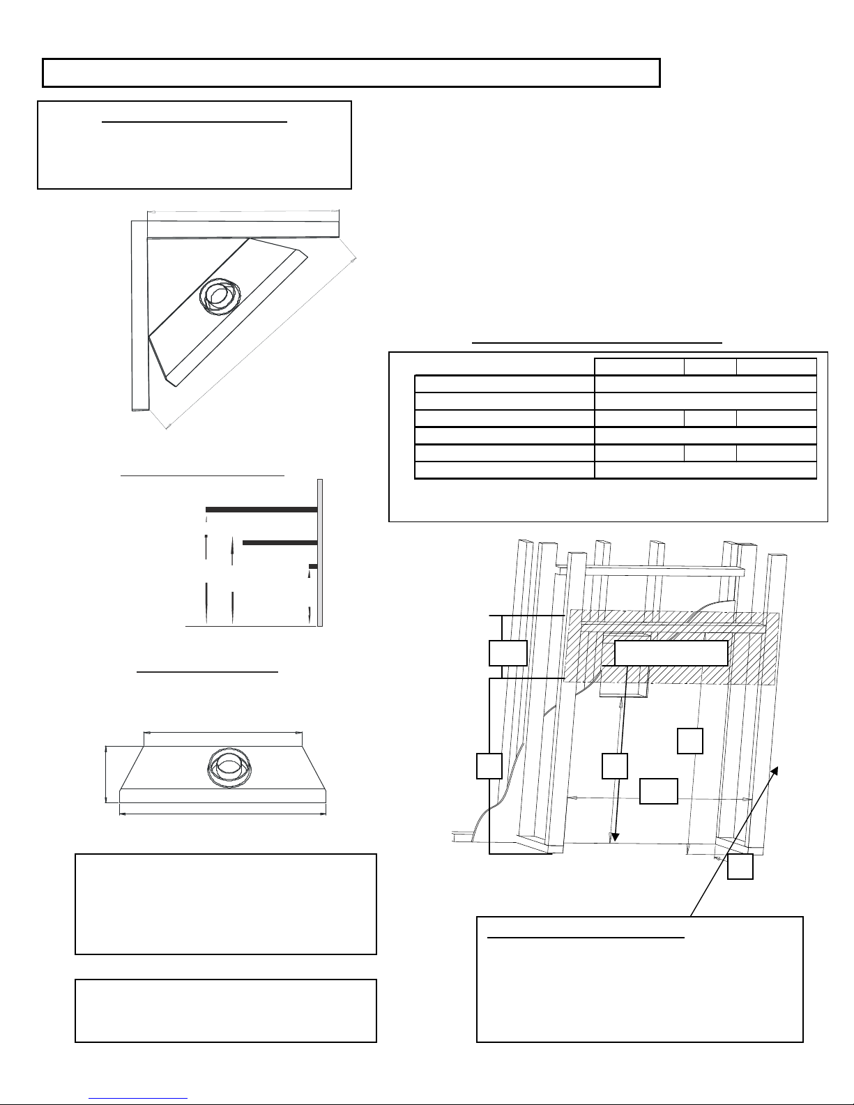
Framing and Clearances
Two sets of dimensions apply.
Standard Install A140cm/-55” B-100cm/39 ½”
Cleanface Install A-148cm/58 ½ B- 105cm/41¼”
Zero Corner
Clearance
Corner installation Dimensions
B
Note: Make sure that you allow for installation of any
wiring, such as the fan, remote control or wall switch
before applying finishing material.
The following diagram shows a typical framed installation.
All clearances must be adhered to. Combustible material
such as timber must not be placed any closer to the
appliance than the stand-offs allow.
Maintain required clearance around the vent pipe (see page
5).
Combustible material: Such as wood, compressed paper,
plant fibers, plastics or any material capable of igniting and
burning.
Depth
14”
A
Mantle c lear anc es
*U nit to 3/4” trim is 8 ”
10”
MB-42 Dimensions
36”tall
Back Width 34”
10” mantle
6” mant le
8”
6”
¾” mantle
6
Appliance Finished Enclosure Dimensions
Standard louver Unit Cleanface Cleanface Tileless
A Width of Across Opening 42.5" 42.5" 43.75"
B Height of Shelf from Appliance bottom 45" 55" 55"
C Appliance bottom to Non-combustible 36" 36" 35"
D Non-combustible panel height 9" 19" 20"
E Total depth of lintle (including wall board) 14" 16.5" 16.5"
F Termination center from appliance bottom 42" 42" 42"
8”
D
C
Non combustible
0
.
F
0
3
4
5
.
2
A
5
.
B
5
4
width 42
Inside framed size 11” X 11”for termination:
CFH Part No. RV58, Weatherguard model
-use
with 1” flange RVF58.
Please note: Wall thimble (Part No. WT58) must
be used for horizontal terminated installations.
Note: This fireplace does not require a hearth
extension and may sit directly on combustible
materials
14
.
0
E
Clearance To Adjacent Sidewalls
The MB42 can be fitted with 0” Sidewall clearance in
either standard louvered or Cleanface installations. If
one of the Cleanface Surrounds is used framing
should be offset 2 ¼” to accommodate the addition
front width.
4
e
h
(
.
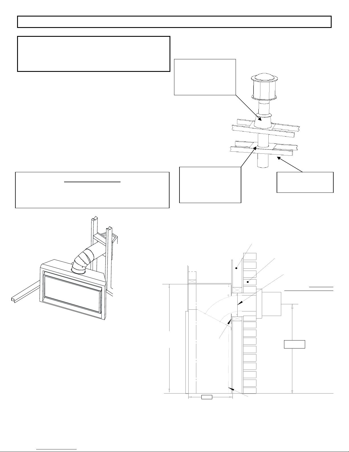
Vent Clearances
Note: Make sure that you allow for installation of any
wiring such as the fan remote control or wall switch before
applying finishing material.
•The following diagram shows a typical framed installation.
All clearances must be adhered to. Combustible materials such
as timber must not be placed any closer to the appliance than
the stand-offs allow.
•Maintain required clearance around the vent pipe:
Horizontal -1” bottom, 1” sides, 2”top
Vertical – 1” around (with the exclusion through the firestop)
•Combustible material: Such as wood, compressed paper, plant
fibers, plastics or any material capable of igniting and burning,
whether flame proofed or not, plastered or un-plastered.
Use a roof flashing
and Storm Collar
whenever vent passes
through the roof
For corner rigid vent installation two 30 degree Elbows are
required. Wall thickness exceeding 2” X 4” construction may
require an additional extension pipe.
Corner Installation
min. Louvred unit
45"
55" for C le a nfa c e un it s
clearance to shelf
if made o f c ombu stible
material
Use a firestop
whenever vent pass
through an overhead
floor or ceiling
Enclosure space around and above
the applian ce m ust be left free of any
obstruction.
fire s to p
Use a support box
on exposed vent
0" if Non-c omb u st ib le
such as brick or stone
Minimum termination op
10" x 10" insid e t o insid e w
passing through combusti
ext e rior wa ll. Wall Thim b le
Part # 942) mu st be used
38"
minimum
15.5"
1" rear clearance
5
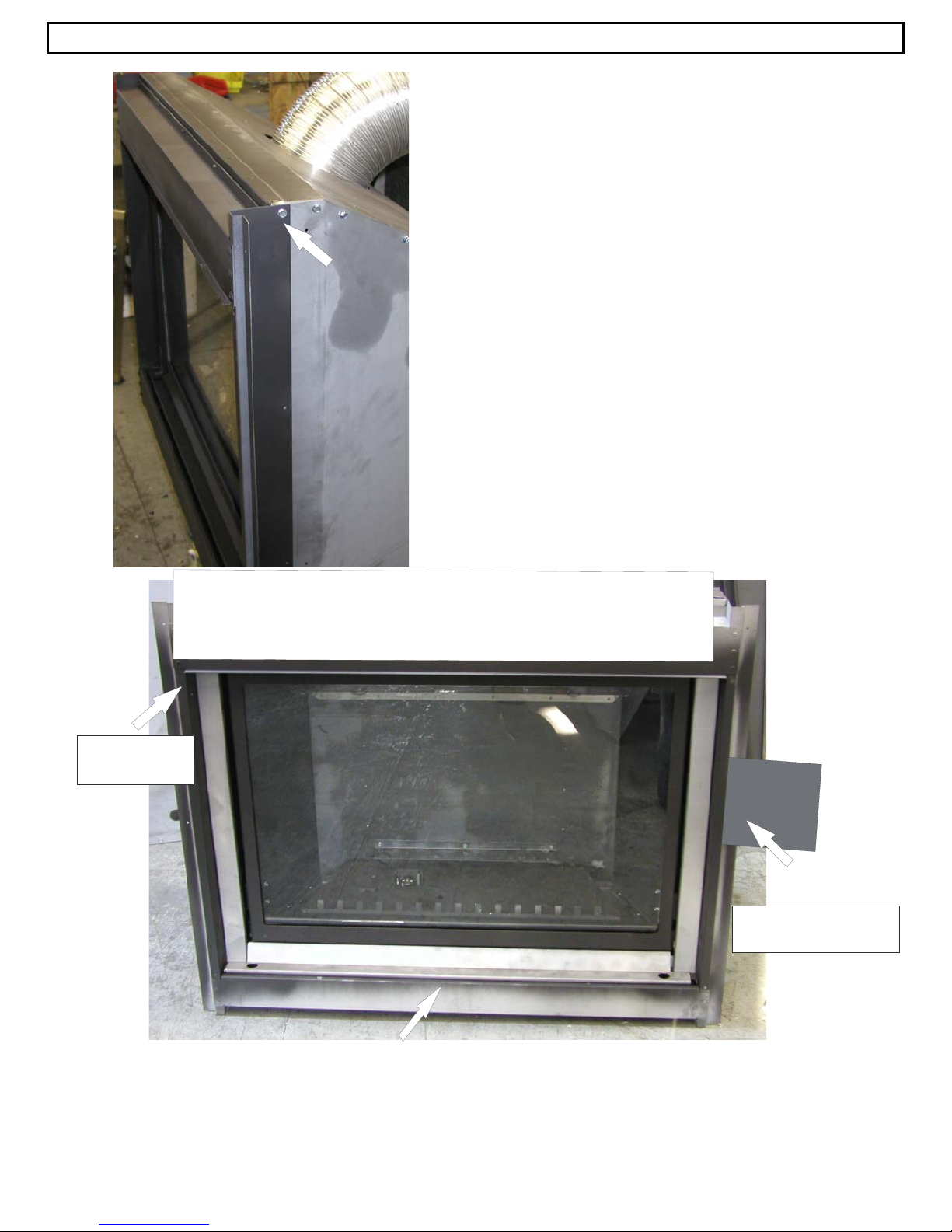
Installation of Clean Face Kits Models CFLK42 & CFLK42T
The Optional CFLK-42 Cleanface surround must be
attached onto the MB42 Fireplace unit before
installation. Each CFLK42 includes 4 self tapping
screws which are used to secure the side panel to the
left and right faces of the MB42 as shown. As note
in the photo the larger horizontal panel is on the top
self tapping screws in
pre-drilled holes.
Once the CFLK42 or CFLK42T Tile front has been
attached and the unit installed into the new construction
A non combustible panel must be fastened above the
unit. Part No. CFLK42/TNBC
.
Lip goes at the
top as shown.
Non combustible panel is installed Here
Overlap side so it is flush
with the opening as shown.
Finishing Cover is set in place at completion of installation
6
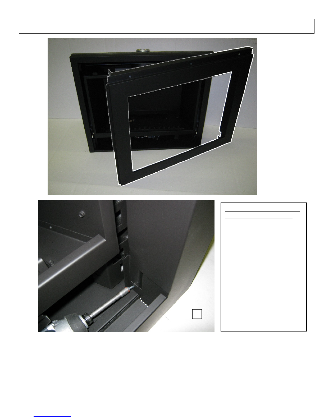
Installation for Cleanface CFLK42T Tileless front
Please note that the top of the
frame is the panel with the
folding metal end tabs
1) Align frame so that the
inside flanges slide
into the chassis off the
fireplace opening. The
metal tabs on the
bottom of the flanges
are for the purpose of
fastening the bottom
as shown in the
illustration. A tapping
screw is required for
each side.
7
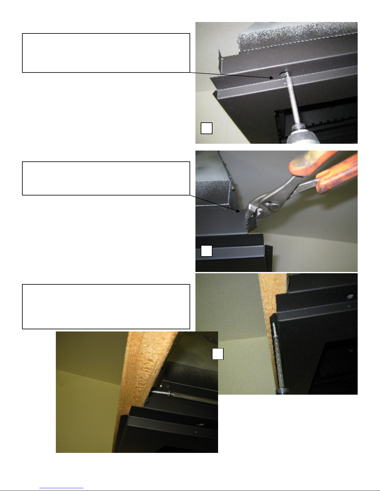
2) Frame top is secured to the fireplace with three
tapping screws. The holes for the screws are
accessed through the three 5/8” round opening.
3) Once the frame is secured on the fireplace the top
end tabs need to be folded up 90 degrees. A pair of
pliers will be required.
4) After the Assembly is set in place the eight (8)
wood screws are used to secure the unit to the wood
framing. A non combustible panel must be
fastened above the unit.
8
 Loading...