

®
®
INSTALLATION MANUAL
Models: LEW28UD, LEW29UD, LEW32UD, LEW40UD, LE48WTUD & LE48CWTUD
3KRQH)D[$GGUHVV'HODQ\5G:DXNHJDQ,/
5(9
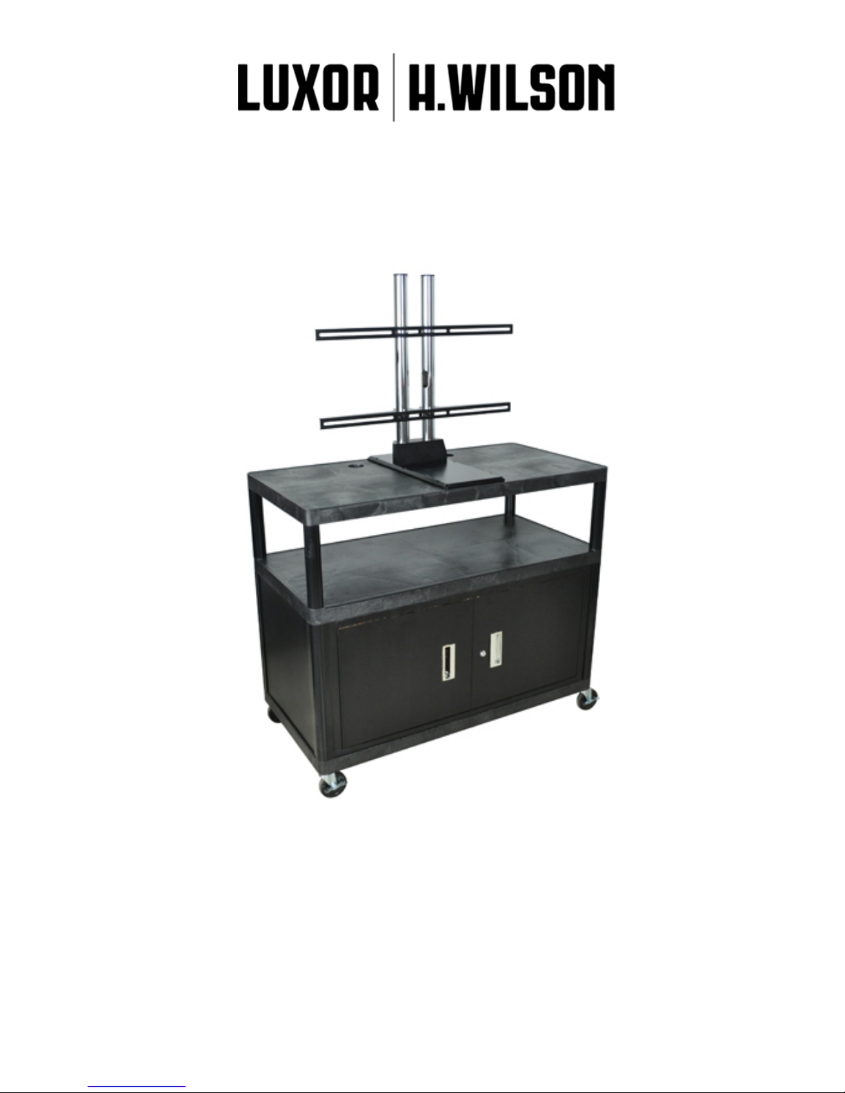
FLAT PANEL DISPLAY CART
LEWUD & LEWCUD Series

LEWTUD & LEWCTUD Series
Thank you for your purchase. The LEWTUD & LEWCTUD Series are totally integrated mount/cart
solutions for 32”-50” at panel displays. To truly appreciate the capabilities and versatility of the
at panel display cart, please read this installation manual completely.
®
Table of Contents
®
Warning Statements
Part Lists
Cart Assembly Instructions
Display Instructions
Cabinet Pack Instructions
Warning Statements
Warning:
Warning:
LUXOR FURNITURE DOES NOT WARRANT AGAINST DAMAGE CAUSED BY THE USE OF ANY LUXOR FURNITURE
PRODUCT FOR PURPOSES OTHER THAN THOSE FOR WHICH IT WAS DESIGNED OR DAMAGE CAUSED BY
UNAUTHORIZED ATTACHMENTS OR MODIFICATIONS, AND IS NOT RESPONSIBLE FOR ANY DAMAGES, CLAIMS,
DEMANDS, SUITS, ACTIONS OR CAUSES OF ACTION OF WHATEVER KIND RESULTING FROM, ARISING OUT OF OR
IN ANY MANNER RELATING TO ANY SUCH, ATTACHMENTS OR MODIFICATIONS.
THE FLOOR SHOULD BE CAPABLE OF SUPPORTING A MINIMUM WEIGHT OF 160 LBS. IF NOT, THE FLOOR MUST
BE REINFORCED. THE WEIGHT OF THE FLA T P ANEL SHOULD BE NO MARE THAN 160 LBS. PROPER INST ALLATION
PROCEDURES BY QUALIFIED PERSONNEL AS OUTLINED IN THE INSTALLATIONS INSTRUCTIONS MUST BE
ADHERED TO. FAILURE TO DO SO COULD RESULT IN SERIOUS PERSONAL INJURY.
2
3-5
6-10
11-14
15
Warning:
Warning:
Warning:
Warning:
Questions/Concerns:
SAFETY MEASURES MUST BE PRACTICED AT ALL TIMES DURING THE INSTALLATION OF THIS PRODUCT. USE
PROPER SAFETY GEAR AND TOOLS FOR THE INSTALLATION PROCEDURE TO PREVENT PERSONAL INJURY.
PRIOR TO THE INSTALLATION OF THIS PRODUCT, THE INSTALLATION INSTRUCTIONS SHOULD BE READ AND
COMPLETELY UNDERSTOOD. THE INSTALLATION INSTRUCTIONS MUST BE READ TO PREVENT PERSONAL
INJURY AND PROPERTY DAMAGE. KEEP THESE INSTALLATION INSTRUCTIONS IN AN EASILY ACCESSIBLE
LOCATION FOR FUTURE REFERENCE.
DO NOT INST ALL ON A STRUCTURE THA T IS PRONE T O VIBRATION, MOVEMENT OR CHANCE OF IMP ACT. F AILURE
TO DO SO COULD RESULT IN DAMAGE TO THE DISPLAY AND/OR DAMAGE TO THE MOUNTING SURFACE.
DO NOT INSTALL NEAR HEATER, FIREPLACE, DIRECT SUNLIGHT, AIR CONDITIONING OR ANY OTHER SOURCE OF
DIRECT HEA T ENERGY. FAILURE TO DO SO MA Y RESUL T IN DAMAGE T O THE DISPLAY AND COULD INCREASE THE
RISK OF FIRE.
CALL CUSTOMER SUPPORT @ 847.244.1800 OR 800.323.4656
2
®
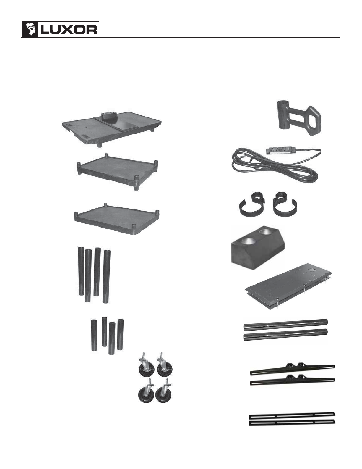
LEWTUD & LEWCTUD Series
Part List:
NOTE: Please familiarize yourself with all components contained herein.
NOTE: Please review all WARNING and CAUTION statements (see Page 2) before beginning the
installation of the Flat Panel Display Cart.
1 - Top Shelf
1 - Middle Shelf *
1 - Bottom Shelf
4 - 17.75” Legs
1 - Power Cord Storage Arm **
1 - Power Cord
2 - “E” Clips **
1 - Base Block
4 - Short/Long Legs *
4 - Casters ( 2 Locking, 2 Non Locking)
1 - Cabinet Pack ***
- Not Included with 2 Shelf Units, Length vaires depending on model
*
- Not Included with 2 Shelf Cabinet Pack Units
**
- Not All Units Include a Cabinet Pack
***
1 - Sandwich Plate
2 - Chrome Tubes
2 - Mounting Brackets
2 - Vertical Brackets
3
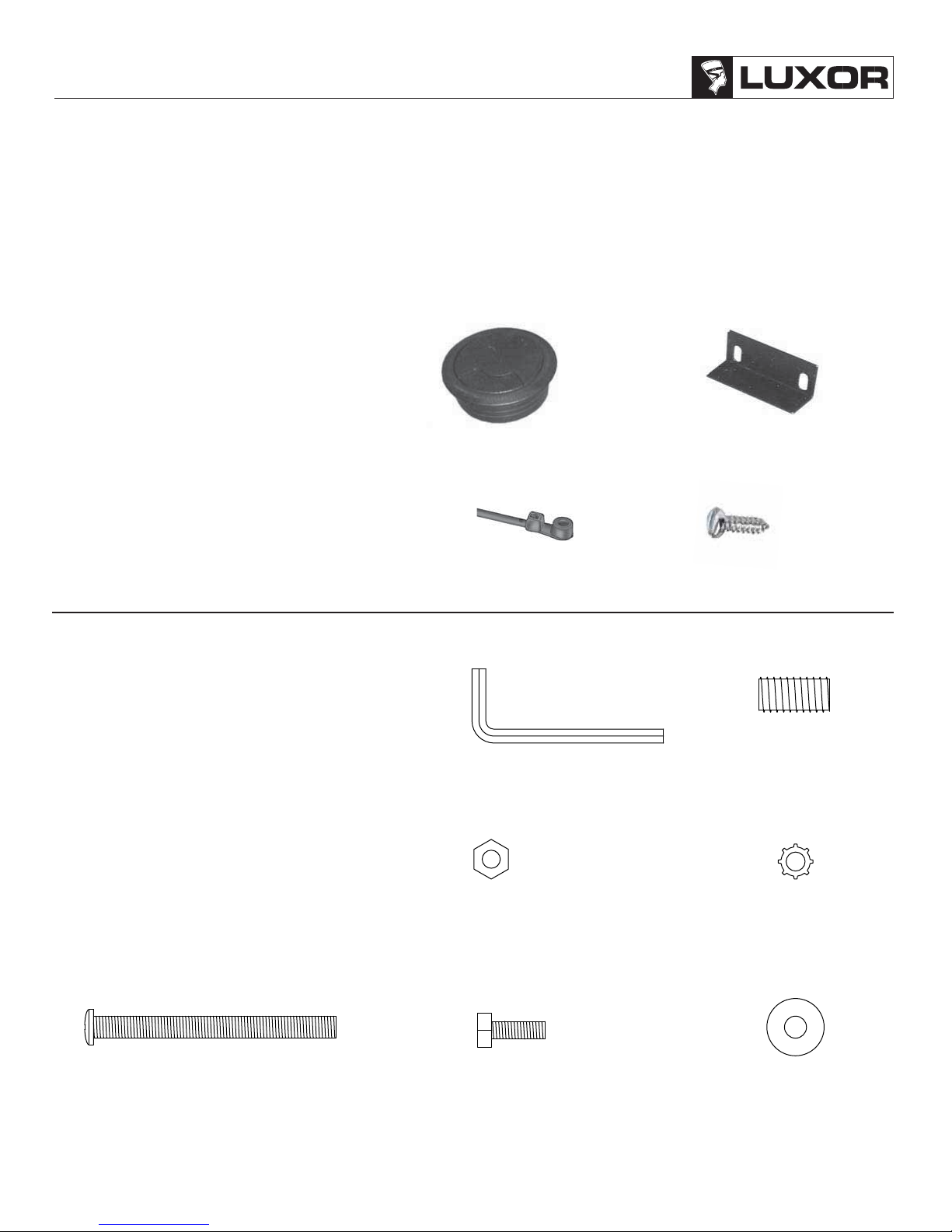
LEWTUD & LEWCTUD Series
Part List Continued:
NOTE: Please familiarize yourself with all components contained herein.
NOTE: Please review all WARNING and CAUTION statements (see Page 2) before beginning the
installation of the Flat Panel Display Cart.
®
1 - Electric Hardware Bag
A.
1 - Grommet Pass-Through
B.
1 - Power Cord Retainer Clip
C.
4 - Cord Management Ties
D.
4 - Slotted Self Tapping Screws
1 - Sandwich Plate Hardware Bag
E.
1 - Allen Wrench
F.
6 - M8 Set Screws
G.
6 - M5 Nuts
H.
6 - M5 Lock Washers
I.
6 - M5 x 55 mm Phillips Head Screws
J.
5 - M5 x 12 mm Hex Head Screw
K.
5 - M5 Washers
A.
C.
E.
B.
D.
F.
I.
4
G.
J.
H.
K.
®
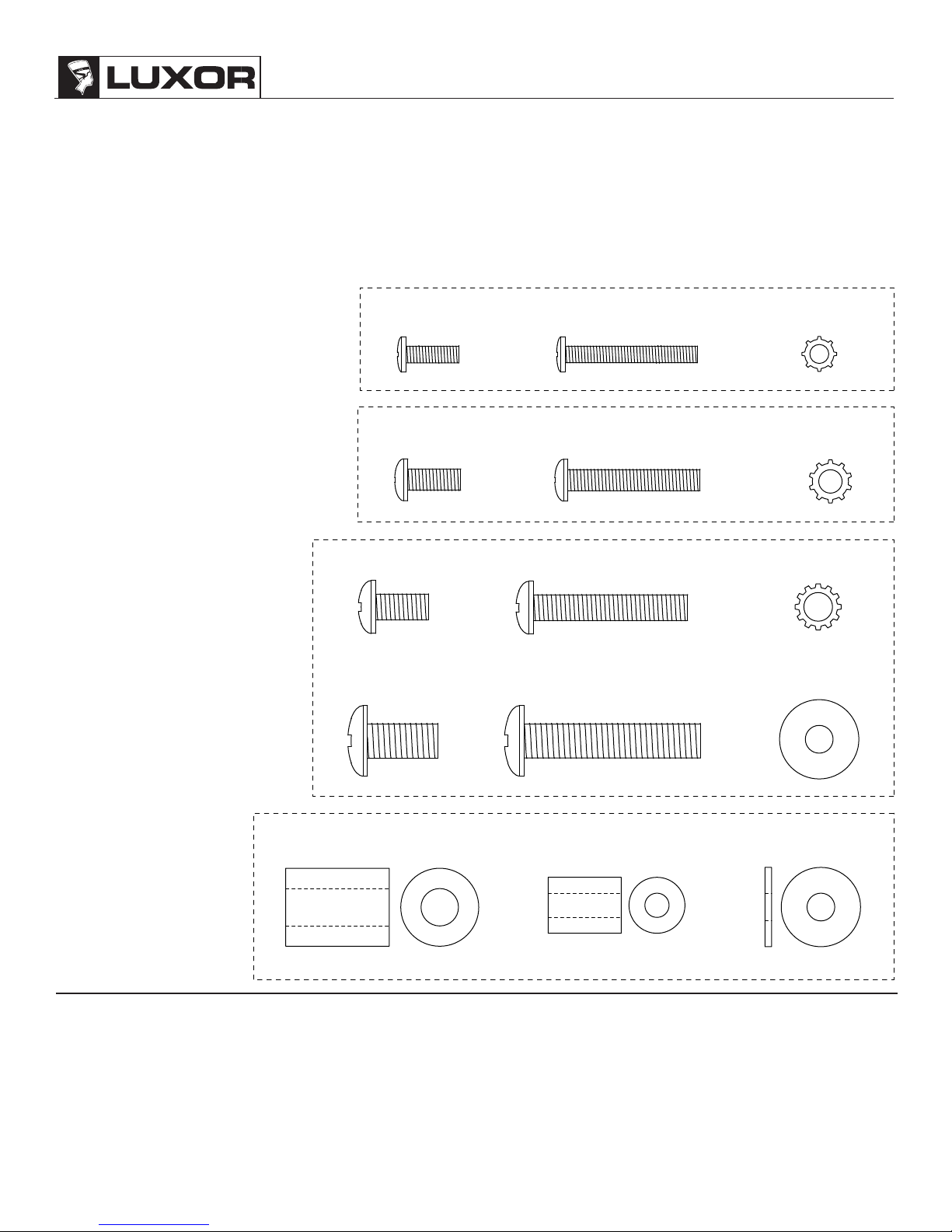
LEWTUD & LEWCTUD Series
Part List Continued:
NOTE: Please familiarize yourself with all components contained herein.
NOTE: Please review all WARNING and CAUTION statements (see Page 2) before beginning the
installation of the Flat Panel Display Cart.
1 - Display Connection Hardware Bag
Section 1
L.
4 - M4 x 12 mm Screws
M.
4 - M4 x 30 mm Screws
N.
4 - M4 Lock Washers
Section 2
O.
4 - M5 x 12 mm Screws
P.
4 - M5 x 30 mm Screws
Q.
4 - M5 Lock Washers
Section 3
4 - M6 x 12 mm Screws
R.
4 - M6 x 35 mm Screws
S.
4 - M6 Lock Washers
T.
4 - M8 x 16 mm Screws
U.
4 - M8 x 40 mm Screws
V.
4 - M8 Washers
W.
Section 4
4 - Large Nylon Inserts
X.
4 - Small Nylon Inserts
Y.
4 - Washers
Z.
R.
U.
O.
L.
S.
M.
P.
N.
Q.
T.
V.
W.
Tools Needed
1 - Phillips Screw Driver
1 - Flat Tip Screw Driver
1 - Rubber Mallet
1 - 5/16 or 8 mm Wrench
1 - Soft Material/ Blanket
1 - 1/8” Diameter x 3”+ Length Thread Depth Indicator
1 - Pencil (Marking Thread Depth Indicator)
1 - Ruler or Tape Measure
X.
Y.
Z.
5

LEWTUD & LEWCTUD Series
LEWTUD & LEWCTUD Assembly Instructions
®
Long Legs
Caster Wheels
Bottom Shelf
Rubber Mallet
Step 1. Push the four casters firmly into the holes in each
corner of the bottom shelf.
Important: Casters must be fully seated. Tap firmly with
rubber mallet to properly seat casters.
Center Shelf
Rubber Mallet
Rubber Mallet
Bottom Shelf
Step 2. Insert the 4 long legs into each corner. Using the
rubber mallet, firmly tap each leg unit it is seated securely into
position.
NOTE: If you have a cabinet pack, go to page 15 and follow the
cabinet pack instructions.
NOTE: If you have a 2 shelf unit continue to step 5.
Short Legs
Rubber Mallet
Step 3. Position the center shelf over the long legs and insert
each mounting post into each leg. Using a rubber mallet, firmly
hammer center shelf into legs until all four legs are seated (flush)
against the surfaces of both shelves.
Step 5. Before installing the top shelf, slide the power cord storage
arm over the short leg on the handle side. The power cord storage arm
will allow the user to easily store the power cord while allowing easy
extraction when the cord is needed.
6
Step 4. Push remaining 4 short legs onto leg posts of center
shelf. Tap firmly into place using the rubber mallet.
Power Cord Storage Arm
Note: Not included in all
models.

®
k
r
LEWTUD & LEWCTUD Series
Electrical Assembly and Cable-Track Management System
Your Flat Panel Display Cart incorporates the Cable-Track™ Cord Management System. This exclusive feature
manages electrical cords, keeping them safely out of the way. This system includes a 3-outlet, 15 foot surge
suppressing electric assembly (U.L. and C.S.A. listed) which is built into the safety handle. Please review these
instructions carefully to maximize the added safety provided by Luxor’s Cable-Track™ Cord Management System.
Parts List
spilc-”E“ - 2 (A.)droc rewop detcetorp egruS - 1
s (C.)eit tnemeganam droC - 4 (B.)pilc reniater droc rewoP - 1
4 - Sheet met
al screws (D.)
Handle Plug Housing
Step 6. Firmly seat the 3-plug electric assembly
unit into the handle plug housing (the
top shelf of the cart will need to be
turned over in order to access the
underside of the handle).
Power Strip
Screwdrive
Sheet Metal Screw
Power Strip Retaining Bracket
Cord Management Tie
Cord Retaining Trac
Step 7. To secure the power strip, use the
power strip retaining bracket and
two (2) sheet metal screws and attach
using a flat tip screwdriver.
Step 8. After the power strip has been
mounted, route the power cord through
the cord retaining track.
Step 9. Attach the cord management tie into
the starter holes using a sheet metal
screw. Cut off any excess.
Step 10. Secure the power cord using the cord
management tie.
7

LEWTUD & LEWCTUD Series
Base Mount Assembly and Installation
A A A
A A A
Step 11. Determine where the mounting points are on the top shelf of the Luxor Cart (Arrows).
A – Sandwich Mounting Plate Mounting Points.
®
M5 x 12 mm Hex
Head Screw (J.)
M5 Washer (K.)
Upper Sandwich Plate
Base Block
Step 12. After locating the mounting points for the base block, it is now time to attach the base block to the
upper sandwich plate.
Step 13. Line up the mounting holes on the upper sandwich plate with the mounting holes on the base block.
Step 14. Once the holes are lined up, use 5 - M5 x 12mm Hex head screws (J.), and the 5 - M5 Washers (K.)
to attach the two units together. Tighten them with a 8 mm or 5/16” wrench.
8

®
LEWTUD & LEWCTUD Series
Upper Sandwich
Plate Mounting
Point
Luxor Cart
Mounting Point
Step 15. Place the upper sandwich plate flat on the top shelf of the Luxor Cart. Line up the mounting holes that are
located on the upper sandwich plate with the mounting holes that are located on the top shelf.
Step 16.
NOTE: At this time, have an assistant hold the lower sandwich plate in place while the screws are being threaded
into place. Insert 6 - M5 x 55 mm Phillips screws (I.) into the upper sandwich plate. With the help of an assistant, align
the bottom sandwich plate to the top plate, and thread the lock washer (H.) and Nut (G.) onto the screw. With a 8 mm
or 5/16 wrench and the phillips screwdriver, tighten the plates together.
NOTE:
The order from top to bottom: M5 x 55mm screw, upper plate, top shelf, lower plate, lock washer and nut.
9

LEWTUD & LEWCTUD Series
t
Final Assembly
®
Top Shelf
Center Shelf
Bottom Shelf
Base Mount Assembly (pre-assembled)
Rubber Malle
Grommet Pass
Through
Power Cord
Storage Arm
Step 17. Place the top shelf over the four (4) short legs that are attached to the center shelf.
Step 18. Once the short legs are lined up with the mounting posts of the top shelf, tap the top shelf firmly onto the short
legs using the supplied rubber mallet. This will complete the first part of the assembly.
Step 19. Place the grommet pass through into the hole located behind the base block.
10

®
LEWTUD & LEWCTUD Series
Thread Depth Indicator
1. Insert the thread depth indicator through the thread inserts found on the back of the at panel display to
make sure the inserts measure the same full depth and mark it with a pencil (see below).
2. Locate the correct diameter screw for the thread insert from the display connection hardware bag. Compare
your markings to the screws (supplied).
3. If your selected screw is longer than the marking on the thread depth indicator, DO NOT USE this screw.
4. The screw length must not bypass the marking. Select another screw size, until you nd one that comes closest
to your mark without going past.
Inverted flat panel
display
Marking the depth
Screw
Thread depth
indicator
Marking
Thread insert
Screw
Marking
Thread depth
Indicator
Thread depth
indicator
11

LEWTUD & LEWCTUD Series
Stand Assembly
®
Mounting Points
Mounting Points
Step 21
. Place the display on a soft and flat surface.
Step 22. Locate the mounting points that are on the back of the display.
Screwdriver
Step 23. Place the mounting brackets over the mounting points.
NOTE:
Please refer to page 4 to determine whi ch mounting screws and spacers (if applicable) will be used.
Step 24. Select the appropriate hardware and attach the mounting brackets to the display using the mounting hardware
and respective lock washer.
12

®
M8 x 16mm
Socket Head
Set Screw
LEWTUD & LEWCTUD Series
Support Pole
Allen Wrench
Step 25. Slide each support pole into the mounting bracket.
Step 26. Make sure the support poles are even (see NOTE:
with the Allen wrench (supplied).
Bottom of Display
Bottom of Support
Poles
below), and then tighten the M8 x 16 set screw
3-1/4”
Before tightening the M8 x 16mm socket head screws and placing the display assembly into the base
NOTE:
mounting block, make sure that the measurement from the bottom of the support poles to the bottom of the
display measures 3-1/4”. This measurement will allow for correct and even spacing once the display assembly
is placed into the base block.
13

LEWTUD & LEWCTUD Series
®
Support Poles
Display
Mounting Brackets
Base Block
TWO PEOPLE WILL BE NEEDED FOR THE FOLLOWING STEPS.
Step 27. After the assembly has been put together, make sure all the hardware is tight.
Step 28. Two people should carefully lift the assembly and place the bottom of the support poles into the base block.
Step 29. Once the support poles are seated, tighten the M8 x 16mm socket head set screws using the Allen wrench
(supplied).
14

®
Bottom Shelf
LEWTUD & LEWCTUD Series
Side Panel
Rubber Band
1. Place the included rubber band
around the legs.
Back Panel Front Panel
2. Insert the side panels.
3. Insert the back panel.
NOTE: If you have a 2 shelf unit go back to Step 6 (page 7).
NOTE: If you have a 3 shelf unit go back to Step 3 (page 6).
4. Insert the front panel.
15
 Loading...