

Page 1
Direct Vent and B-Vent Gas Fireplace Inserts
Model LDV-3, LDV-4, LDV-5, LDV-6
LBV-3, LBV-4, LBV-5, LBV-6
Installation and Owner’s Manual
PLEASE NOTE: This product has been manufactured using steel and screws. As a
result, there are many sharp edges that can easily cut exposed skin. It is highly
recommended that you wear proper protective gloves while installing the unit, and
during routine cleaning or maintenance..
PLEASE READ INSTRUCTIONS CAREFULLY BEFORE
INSTALLING AND OPERATING THE APPLIANCE
WARNING: If the information in these instructions are not followed exactly, a fire or
explosion may result causing property damage, personal injury, or loss of life.
Installation and service must be performed by a qualified installer, service agency, or the
gas supplier.
This appliance may be installed in a permanent home, manufactured mobile home, and is
suitable for bedroom or sitting room.
FOR YOUR SAFETY
DO NOT store or use gasoline or any other
flammable vapors or liquids within the vicinity of
this or any other appliance. Keep fireplace area
free from combustible materials.
IN THE EVENT THAT YOU SMELL GAS
-Do not try to light any appliance
-Open windows
-Do not touch electrical switches
-Do not use any phone in your building
-Extinguish any open flame
-Call your gas supplier from a neighbors phone
and follow the gas suppliers instructions.
-If you cannot reach the gas supplier, call the fire
department
Made in Canada by:
Canadian Firehearth.ca
Unit 106 5570 268 Street
Langley B.C Canada,
V4W 3X4
857 6664
857 5567
www.firehearth.ca
Installer: Please leave this manual with the customer
Customer: Please keep instructions for future reference
Page 2

Attention Installer
The following label has been provided by
the manufacturer and MUST be fixed into
the installation area.
The installer must mechanically attach the marking supplied with the gas fireplace
insert to the inside of the firebox of the fireplace into which the gas insert is
installed (see label 1.29.7-g).
1.29.7-g Marking (Same materials and manufacturer as Rating Place.)
WARNING: This fireplace has been converted for use with a gas fireplace insert
only and can not be used for burning wood or solid fuels unless all original parts
have been replaced, and the fireplace re-approved by the authority having
jurisdiction.
Installation and repair should be done by a qualified service person. The appliance
should be inspected before use and at least annually by a professional service
person. More frequent cleaning may be required due to excessive lint from
carpeting, bedding material, etcetera. It is imperative that control compartments,
burners, and circulating air passageways of the appliance be kept clean.
Page 3
Date Purchased:_________________________________________________
Dealer:_________________________________________________________
Installer:________________________________________________________
Phone:___________________________ Cell:______________________
Serial Number:___________________________________________________
Welcome!
Congratulations on the purchase of your new Luxor Gas Fireplace! We hope
you’ve had an easy and enjoyable time choosing from our line of products, and
we certainly appreciate your business. Please take some time to read through
the following information, and make sure to heed all of the warnings. Even
though our fireplaces are easy to install and simple to operate, they are still gas
burning units with some inherent dangers if not careful.
.
Pre-Start Up Checks
FOR YOUR SAFETY - Read before lighting
DO NOT: Use tools to operate controls. Use only you hand to push in and turn controls.
DO NOT: Abuse glass doors by striking or slamming shut.
DO NOT: Clean the appliance when hot.
DO NOT: Use this appliance if you smell gas.
DO NOT: Use this appliance if any part has been under water. Immediately call a qualified service technician to
inspect the appliance and replace any part of the control system and any gas control which has been under water.
DO NOT: Obstruct the flow of ventilation air.
GAS SUPPLY
ONLY PERSONS LICENSED TO WORK WITH GAS PIPING MAY MAKE THE NECESSARY GAS
CONNECTION TO THIS APPLIANCE. YOU ARE NOW READY TO HOOK UP THE GAS SUPPLY. BE SURE
GAS PLUMBING INSTRUCTIONS AND ALL PROVINCIAL AND LOCAL CODES ARE CAREFULLY FOLLOWED.
USE APPROVED FLEXIBLE GAS CONNECTIONS OR RIGID PIPING, DEPENDING ON PROVINCIAL AND
LOCAL CODES, TO ATTACH BURNER TO GAS SUPPLY. BE SURE TO USE PROPER SIZE GAS SUPPLY
LINE.. CAREFULLY CHECK ALL CONNECTIONS FOR GAS LEAKS WITH SOAP AND WATER SOLUTION.
EACH INSTALLATION MUST CONFORM TO ALL LOCAL, PROVINCIAL, AND NATIONAL CODES. REFER TO
THE NATIONAL FUEL GAS CODE, LOCAL ZONING AND CODE AUTHORITIES FOR DETAILS ON
INSTALLATION REQUIREMENTS.
This appliance is only for use with Natural Gas as indicated
On the rating plate.
Note: The copy in the manual is for reference only. In the event of a discrepancy, the
label on the unit is to be taken as the latest version.
Page 1
Page 4
Table of Contents
Page 1: Pre-Start Up
Page 2: Table of Contents
Page 3: Specifications
Page 4: Clearances
Page 5: Direct Vent Venting
Page 6: B-Venting
Page 7: B-Venting
Page 8: B-Venting
Page 9: Door Fitting
Page 10: Electrical
Page 11: Planning
General Safety (Home Owner)
Fire Extinguisher: Every home should have at least one fire
extinguisher. An approved Class A-B-C extinguisher
should be mounted on the wall near an exit and close to
the application, but not so close that accessibility to the
extinguisher could be blocked by a fire. Your local Fire
Department can advise you concerning the most
appropriate location.
Smoke Detectors & Carbon Monoxide Detectors on each
floor of your home to ensure your safety. It should be
located away from the gas appliance and close to the
sleeping areas. Follow the detectors manufacturers
placement installation and maintenance instructions
Page 12: Thermostat Installation
Page 13: Log Installation
Page 14: Log Installation
Page 15: Parts List
Page 16: Lighting Instructions
Page 17: Final Checks
Page 18: Trouble Shooting
Page 19: Trouble Shooting
Page 20: Maintenance
Page 21: Warranty Information
Safety for the installer
-Wear gloves and safety glasses for protection.
-Exercise extreme caution when using ladders or
when on roof tops.
-Be aware of electrical wiring locations in walls
and ceilings.
-Use a back support for heavy lifting.
Vent safety
-Venting must be installed according to local
codes.
Electrical code
When installed, these appliances must be
electrically grounded in accordance with local
codes.
-DO NOT burn ANY materials in this fireplace.
-All occupants of the home, especially children, should be alerted about the hazards of the high surface
temperature and the chance of severe burning or the possible ignition of clothing.
-Young children should be carefully supervised when they are in the same room as the appliance.
-Due to the high temperatures, the fireplace should be installed away from furniture and draperies and out of
traffic area.
-Nothing should ever be placed on or near the surface of the fireplace, including the top of the unit.
-Clothing or other flammable material should not be placed on or near the appliance.
-Make certain the control panel, burners, fans, and venting system are kept clean. Inspection of these systems
should be inspected annually by a qualified service technician.
-Any safety screen or guard removed for servicing the appliance must be replaced prior to operating the
appliance.
-The fireplace, under NO circumstances, should ever be modified.
-Do not operate the appliance with the glass front removed, cracked, or broken. Replacement should be done
by a qualified service person.
WARNING
Page 2
Page 5

SPECIFICATIONS
Note: Always check appliance label for correct information.
MODEL: Luxor Natural Gas
Manifold Pressure 1.6in-3.5in w.c.(0.45-0.87 kPa)
Min. Supply pressure for purpose 5.0in - w.c. (1.0 kPa)
of input adjustment
Max. Supply pressure for purpose 14.0in - w.c. (1.8kPa)
of input adjustment
Orifice size 38 DMS and 42 DMS
High altitude (US) 0-2,000ft. (0-610m) US
Primary Air Opening 1/8in (Minimum)
Electrical Rating 120 V.A.C. System
Circulating fan Variable Speed
Vent System Direct Vent and B-Vent
Log Set Ceramic Fiber
BTU
Model Dimensions
L-DV-3
L-DV-4
L-DV-5
L-DV-6
LBV-3
LBV-4
LBV-5
LBV-6
Width Depth
Height
28½” x 20½” x 12”
28½” x 22½” x 12”
32½” x 22½” x 12”
32½” x 24½” x 12”
LDV LBV
17,000-26,000
17,000-26,000
19,000-31,000
19,000-31,000
Min Max
17,000-26,000
17,000-26,000
19,000--31,000
19,000-31,000
Certification
The Model LDV and B-Vent is listed and certified for the installation in the
U.S.A. and Canada under the following standards:
ANSI Z21.88b CSA 2.33b-2003
Heater Rated: 72% minimum without the fan
Please contact CFH Mfg Inc if you have any questions regarding the
certification of this appliance.
The installation must conform with local codes, or in the absence of local
codes, with the National Fuel Gas Code, ANSI Z223.1 / NFPA 54 in the US,
or the Natural Gas and Propane Installation Code, CSA B149.1 in Canada.
Page 3
Page 6
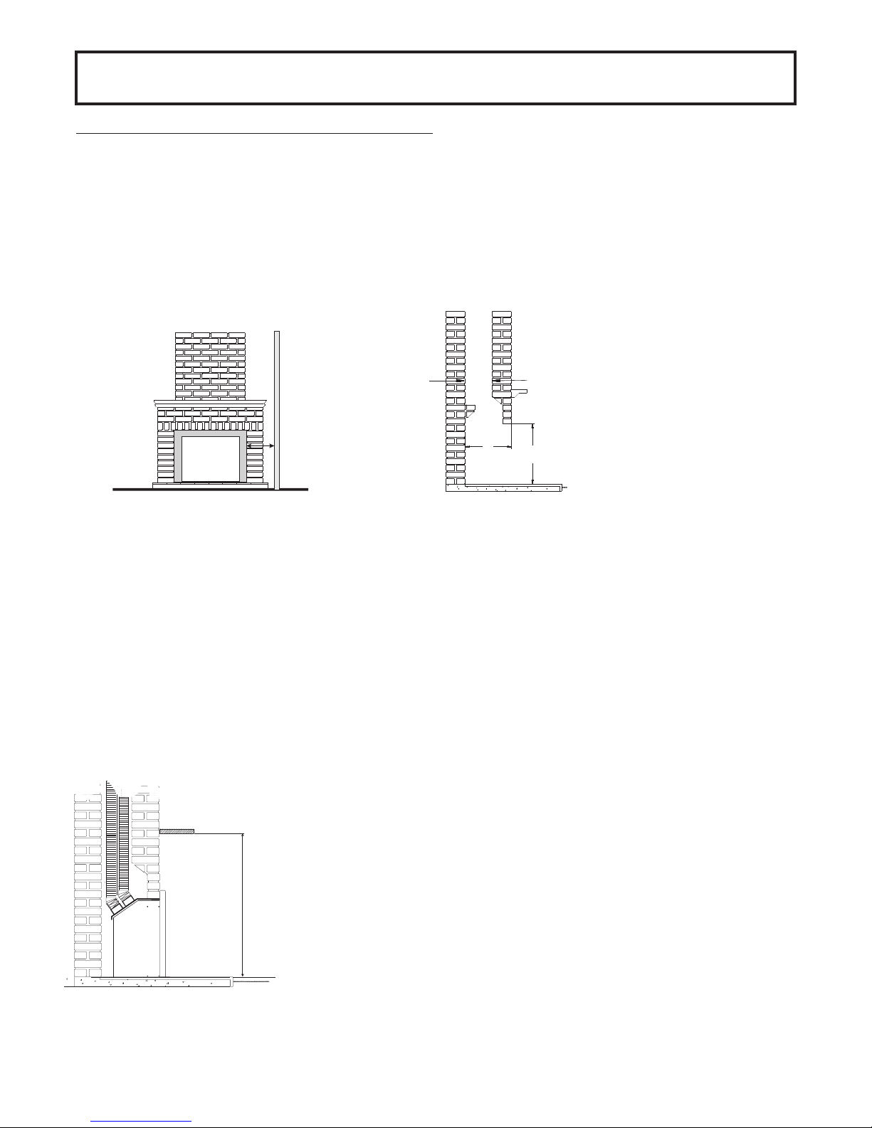
Clearances for Direct Vent
Existing fireplace (Masonry or factory built)
WARNING: Cutting any sheet-metal parts off the fireplace in which the gas fireplace insert is to be
installed is prohibited.
The model Luxor is intended for installation into masonry or listed factory built fireplaces. Masonry
fireplaces must be built according to the requirements of the standards for chimneys, fireplaces, vents
and solid fuel burning appliances, NFPA 211 (Latest Edition) or the applicable National, Provincial, State
or local codes. The figure below shows the minimum install dimensions for the model Luxor.
If the factory-built fireplace has no gas access holes provided, an access hole of 1.5” (37.5mm) or less
may be drilled through the lower sides or the bottom of the firebox in a proper workmanship like manner.
This access hole must be plugged with non-combustible insulation after the gas supply like has been
installed.
Check masonry step does not interfere with
install dimension or vent pipe.
7” X 7” min opening
5“
A
If mantle is combustible see below
for allowable clearances.
B
C
ALL MEASUREMENTS ARE IN INCHES
Model # A B C
L-DV-3 14½ 20½ 30½
L-DV-4 14½ 22½ 30½
L-DV-5 14½ 22½ 34½
L-DV-6 14½ 24½ 34½
Install must be made without modification to the draft hood.
WARNING: Inserts must not be connected to a chimney flue servicing a separate solid fuel
burning appliance.
-Smoke shelves, shields, and baffles may be removed if attached by mechanical fasteners.
-Trim panels or surrounds shall not seal ventilation openings in the fireplace.
NOTE: Make certain a tight connection between the gas fireplace insert flue collar and fireplace chimney are made.
Mantle Clearance
-Fireplace flue damper can be fully blocked open or removed for installation of
the gas fireplace insert.
9“
38“
-The Fireplace and fireplace chimney must be clean and in good working order
and constructed of non-compbustible materials.
-Chimney cleanouts must fit properly.
-Refractory, glass doors, screen rails, screen mesh, and log grates can be
removed from the fireplace before installing the gas fireplace insert.
Note: The model Luxor is certified without requiring a hearth projection,
although local codes may require a minimum hearth projection.
Note: Measurement taken from under side of mantle to
finished floor surface that the unit is seating on.
Page 4
Page 7
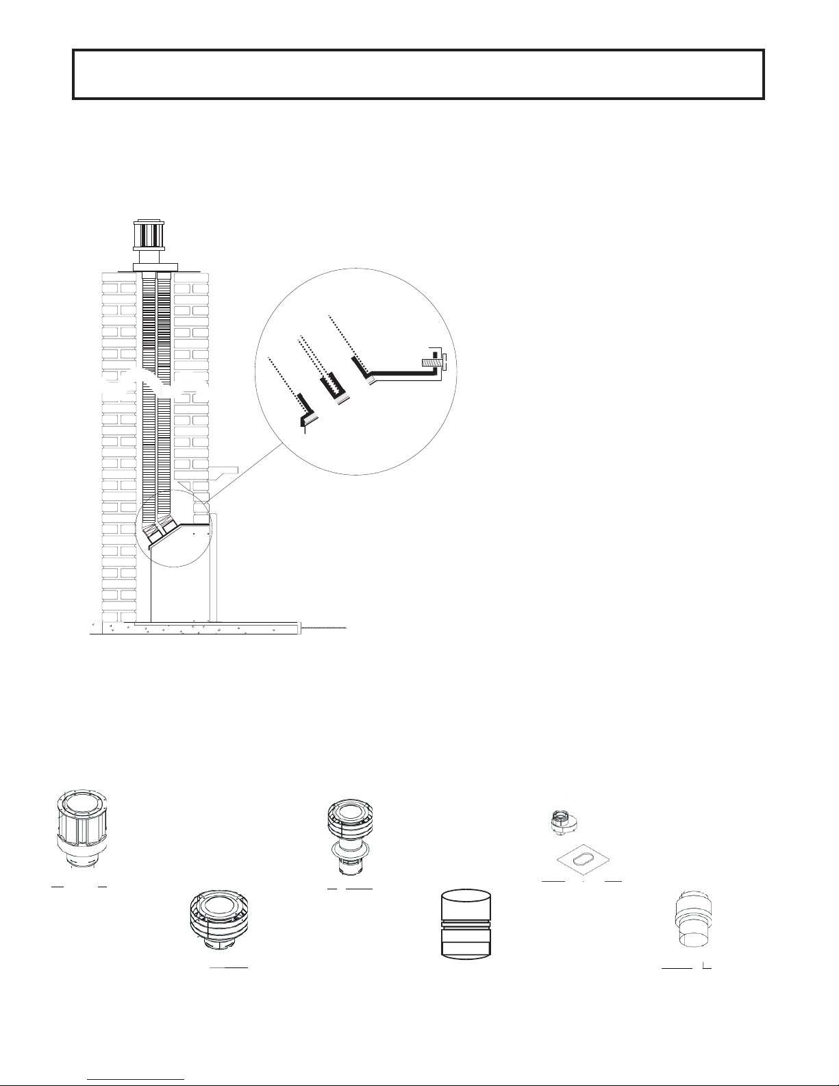
Direct Vent Venting
IMPORTANT: This appliances venting system is room sealed, which
means that there should be no provision to allow room air to be used in the
combustion process.
Note: Only UL Listed 3” Aluminum venting may be used with the model
Luxor.
PLANNING YOUR VENT INSTALLATION
This type of direct vent system may only terminate in the
following way: Vertical termination using a D uravent 3” adapter
and cap (see Vent parts list). There are limitations to the vertical
length to a maximum of 30 feet from the fireplace base, and a
minimum of 8’ from the fireplace top.
When calculating the length of the vent pipe from the outlet of the
appliance to termination, allow for any offsets in the chase and
Apply RTV sealant to the appliance vent pipe and slide over air intake
and exhaust pipes.
Secure using the eight self tapping screws (four per flex)
Slide unit into the opening, taking care not to damage the liner (allow
enough slack for final surround assembly).
WARNING: Failure to position the parts in accordance with these
diagrams or failure to use only parts specifically approved with this
appliance may result in property damage or personal injury.
Never vent appliance into room or building vent only to outdoors. The
vent terminal shall not be recessed into a wall or siding.
At the top of the chimney slide the connector
plate over the two flex liners.
Attach the termination cap to the flex pipes
using the eight screws provided
Finally seal the connector plate to the
chimney (fire cement).
Note: Inspect vent connection prior to installing trim surrounds.
MAINTENANCE: In the event service is required which alters vent system, proper reassembly & resealing of the vent-air
intake system.
Typical components used in above install
991 DV GS cap (high wind)
980 DV GS cap (low profile)
930 DV GS extended cap
Page 5
923GK DV GS Chimney liner kit
2150 DV GS flex
923F DV GS appliance flex connector
Page 8

LBV-Venting
Exiting fireplace (Masonry or factory built)
The model Luxor is intended for installation into masonry or listed factory built fireplaces.
Masonry fireplaces must be built according to the requirements of the standards for chimneys,
fireplaces, vents, and solid fuel burning appliances, NFPA 211 (latest edition) or the applicable
National, Provincial, State , or Local codes. The figure below shows the minimum install
dimensions for the model Luxor.
Check that step does not interfere with
install dimension or vent pipe.
If mantle is combustible, see below
for allowable clearances.
C
10“ (254mm)
9”
5“
A
B
ALL MEASUREMENTS ARE IN INCHES
Model # A B C
L-BV-3 14 21 32
L-BV-4 14 23 32
L-BV-5 14 23 36
L-BV-6 14 25 36
Note: The model Luxor is certified without requiring a hearth projection,
although local codes may require a minimum hearth projection.
WARNING: Any door system or covering installed in front of the LBV Series
inserts must NOT restrict the flow of air required for proper operation.
FDM’s Custom Wire-Mesh Doors are designed and tested for optimum
operating conditions with all models of Luxor Units.
If the fireplace is installed behind glass doors and safety switch must be in
place that will not allow fireplace operation unless the doors are opened.
The minimum distance between the door and the fireplace is 2”. The door
top & side inside dimension must not cover the insert front outside
dimension by more than 1” & 21/2” on the bottom.
38“ (965mm)
Note: Measurement taken from under side
of mantel to finished floor surface that the
unit is sitting on.
Page 6
Page 9

LBV-Venting
Vent location
The vent terminal must be located through the roof.
This ‘b’ vent appliance is designed to operate when an undisturbed airflow hits the outside vent terminal from any
direction. The figure below shows minimum vent cap clearances.
Check local codes for allowable vertical vent terminations
2ft Min
2ft Min
Venting notes:
Where possible avoid the use of joining flex pipe. Do not bend flex pipe over 45°.
2ft Min
Page 7
Page 10

LBV-Venting
Vent Installation:
IMPORTANT: This appliances venting system requires room air for combustion, which
means that there should be provision to allow room air to be used in the combustion
process. The drafthood shall be installed so as to be in the same atmospheric
pressure zone as the combustion air inlet to the appliance. Draft openings must not be
covered or blocked.
Note: Only UL Listed Aluminum (exhaust) 4” flex or listed ‘B’ vent pipe
may be used with the model Luxor.
The minimum venting required on the gravity vented models for safe operations is 11
feet above the appliance base with one-foot horizontal offset (with 90 degree elbows.)
PLANNING YOUR VENT INSTALLATION
When calculating the length of the vent pipe from the outlet of the appliance to
termination, allow for any offsets in the chase and sufficient vertical height above the
roof.
At the top of the chimney slide the connector plate over the flex liner.
Attach the termination cap to the flex pipe using the four screws
provided. Finally seal the connector plate to the chimney
(fire cement).
t
e
e
f
2
m 1
mu
i
in
M
WARNING: Failure to position the parts in accordance with these
diagrams or failure to use only parts specifically approved with this
appliance may result in property damage or personal injury.”
Apply RTV sealant to the appliance vent pipe and slide over
exhaust pipe.
Secure using the four self tapping screws provided.
Slide unit into the opening, taking care not to damage the
liner (allow enough slack for final surround assembly).
Note: Inspect vent connection prior to installing
trim surrounds.
Page 8
Page 11

Door Fitting
WARNING: Do not abuse the appliance’s glass by striking, slamming or similar trauma. Do not use the
appliance with the door removed, glass panel cracked or broken. Only use glass approved for use with
this heater. Do not use substitute materials. Replacement of the panel should only be carried out by a
licensed qualified service person. .
Window Removal
• Open bottom grill assembly.
• Open the two clasps located on bottom of firebox floor.
• Lift out the bottom of the door and slightly lift door to unhook assembly from the top clips.
Window Replacement
• Locate the top door channel over the top firebox relief brackets.
• Locate the bottom two clasps and close clasps.
• Pull the top of the window forward and release to check that the it opens slightly and returns in the
event of delayed ignition.
If glass breaks, remove all broken glass inside fireplace.
To install the glass, simple hold at a 45 degree angle and line up the groves as
shown above. Do not force. Once in the groves, the door should simply close
down into place.
Once the door closes against the insert,
simply lock the clips firmly into place. Again,
do not force the door. All parts are crafted to
fit into place with proper installation.
Page 9
Page 12

Electrical
WARNING
Electrical Grounding Instructions
This appliance is equipped with a three pronged (grounding) plug for your protection
against shock hazard and should be plugged directly into a properly grounded three prong
receptacle. Do not cut or remove the grounding prong from this plug.
L1(BK)
Fan Motor
Variable Speed Control
Thermal disk (close on rise)
L2 (W)
G
The appliance, when installed, must be electrically grounded in accordance with local codes or, in the
absence of local codes, with the National Electrical Code, ANSI/NFPA 70, or the Canadian Electrical
Code, CSA C22.1.
CAUTION: Label all wires prior to disconnection when servicing controls.
Wiring errors can cause improper and dangerous operation.
VERIFY PROPER OPERATION AFTER SERVICING
Page 10
Page 13

Planning
The recommended order of installation is as follows:
1-Familiarize yourself with this manual.
2-Check the minimum install dimensions and vent installation.
3-Check your local install codes.
4-Check you have the parts and components necessary to complete the installation.
5-Check the gas and electrical supplies are ready.
6-Prepare opening (clean chase, level base etc.)
7-Install Venting.
8-Install base unit and connect vent.
9-Connect gas and electrical supplies.
10-Install operational components and prepared for first test fire.
11-Check to verify adequate accessibility clearance for service & proper operation.
12-Check operation of unit .
13-Take time to explain operation to customer, (most call backs are caused because the customer
does not understand the operation of the unit.)
Existing Gas Supply
-Before interrupting the existing gas supply it is recommended that the following be checked.
-Shut down all gas appliances and carry out a pressure test to insure there are no leaks in the system.
-Before connecting the appliance to the gas supply line, double check that the appliance you have
purchased is designed for the gas type you are using. The gas type markings are located on the certification
label and also on the appliance’s gas valve.
-Check the gas pressure immediately upstream to insure you will be able to supply the minimum inlet
pressure for the appliance. Check your pipe sizing to insure sufficient volume will be supplied to the
appliance
.
Gas Supply Installation
-Provide adequate clearance for the proper installation and checking of the gas connection.
-Have your gas supplier or a qualified gas fitter run a gas supply line into the gas fireplace. The line must be
properly sized and fitted according to the installation codes. Upstream of the appliance supply connection,
the fitter shall provide an easily accessible manual shut-off valve.
-The gas supply pipe should enter the appliance case through the opening at the right side. The supply
pope should be connected to the appliance gas inlet pipe situated at the rightside of the control unit. Supply
line connection to the inlet pipe is 3/8 NPT.
-Use only new black iron or steel pipes or copper tubing if acceptable - check local codes.
Note that in the USA copper tubing must be internally tinned for protection against sulfur
compounds.
-Unions in gas should be of ground joint type. Sealant used must be resistant to the action of all gas
constituents including LP gas. Sealant should be applied lightly to male threads to ensure excess sealant
Pressure testing the supply line for leaks
The appliance and its individual shut-off valve must be disconnected from the gas supply piping system during
any pressure testing of the system at test pressures in excess of ½ psig (3.5 kPa). The appliance must be
isolated from the gas supply piping system by closing its individual manual shut-off valve during any pressure
testing of the gas supply pipping system at test pressures equal to or less than ½ psig (3.5 kPa). Failure to do
so will damage the appliance’s gas valve. Such damage is not covered by the manufacturer’s warranty.
When testing for leaks
-Make sure that the appliance is turned off.
-Open the manual shut-off valve.
-Test for leaks by applying a liquid detergent or soap solution to all joints. Bubbles forming indicate a gas leak.
-Correct any leak detected immediately.
-Never use an open flame to check for leaks.
The pressure test tapping locations are built-in, non-adjustable regulator that controls the burner manifold
pressure. The correct pressure range is shown in the table in the specification section of this manual. The
pressure check should be made with the burner lit.
See lighting instruction section for full operating details.
Page 11
Page 14

Thermostat Installation
Thermostat or wall switch installation
The burner control switch is located in the center of the control department opening. For your convenience,
the unit can also be operated by a thermostat or a wall switch control. Millivolt thermostats are available from
any authorized FDMCo dealer. Please note, bedroom installations require the use of a wall thermostat.
Mount the thermostat or switch in the desired location and run “two conductor thermostat wires” to the
heater’s lower right hand corner, close to the gas supply line.
Note: The thermostat or wall switch MUST be rated for millivolt use.
Minimize splicing in all millivolt wiring and solder all unavoidable splices.
Thermostat Wire Information
AWG
22
20
18
16
14
mm
0.6
0.8
1.0
1.3
1.6
Ft.
10
25
40
64
100
M
3.0
7.6
12.2
19.5
30.5
Flame Quality Adjustment
Air adjustment is located beneath the firebox which is attached to the valve tray. This
venturi adjustment allows for fine tuning of the flame characteristics which may vary due to
climate, altitude, and venting differences.
WARNING: Incorrect adjustment of flame can lead to
improper combustion which can be a safety hazard.
Thermocouple
Flames Types
1. Blue at the base and
light orange above.
Medium height (ideal)
Adjustment
None
Pull Out
Thermopile
2. Mostly blue with little or
no orange
Pilot Checks: A periodic check of the pilot and burner flames should be made. Check after
the fire has been on for at least 30 minutes. The pilot flame must cover the tip of the
thermocouple and thermopile probes, if the pilot flame does not sufficiently cover the
probes it can be adjusted using the pilot adjustment screws found on the front of the gas
valve. The main burner flame patern will vary from appliance to appliancedepending on the
type of installation and climatic conditions.
Push In
Pilot Flame
Electrode
Page 12
Page 15

Log Installation
Make certain that none of the fire
holes or the pilot are blocked while
installing the log set. Logs are
brittle and easily damaged.
Handle with care.
Distribute vermiculite evenly over
the burner. Spread it near and
around the flame holes, but do not
block any of them.
Place large log segment on the
burner using locating device
attached to the burner.
The second segment is to sit on the
small shelf at the rear of the firebox
while leaning the burnt end up on
the first segment as shown.
Lean the third segment against the
top of the second segment, while
resting the bottom in the locator on
the burner.
Page 13
Page 16

Logs Installation Continued
Fiber “ember” material to be
placed sparingly across the front
of the log set. Careful not to
block any of the flame holes.
These installation pictures are with the
optional Brick Set installed. If you do
not have the 3 piece brick set, the
background will be black.
Installation of 3 Piece Brick Set
The brick sets are pre-cut and slide
right into place. Start with the back
section and follow with the sides.
The pieces are very brittle and easily
damaged, so handle with extreme
care.
Page 14
Page 17

Spare Parts
Part No. Description
FD-101 #42 Orifice
FD-102 #38 Orifice
FD-103 SIT Pilot Assembly
FD-104 SIT Gas Valve
LDBV-DR 3 Door Assembly
LDBV-DR 4 Door Assembly
LDBV-DR 5 Door Assembly
LDBV-DR 6 Door Assembly
Fan Components
FF-101Fan kit
FF-102 Heat Sensor
Parts List
Log Set
SIT Pilot Assembly
Variable Speed Fan
WARNING: Failure to position the parts in accordance with the instructions or failure to
use parts specifically approved with this appliance may result in property damage or
personal injury.
Page 15
Page 18

Lighting Instructions
For your safety, read the following before lighting.
WARNING: If you do not follow these instructions exactly, a fire or explosion may result
causing property damage and personal injury or death.
1. This appliance has a pilot which is lit with a push-button piezo lighter. When lighting the pilot, follow
these instructions exactly.
2. Before lighting, smell all around the appliance area for gas. Be sure to smell next to the floor because
some gas is heavier than air and will settle on the floor.
What to do if you smell gas:
-Do not try to light the appliance.
-Do not touch any electric switch, and do not use any phone in your building.
-Immediately call your gas supplier from a neighbors phone & follow the gas suppliers instructions.
-If you cannot reach your gas supplier, call the fire department
3. Use only your hand to push in or turn the gas control knob. Never use tools. If the knob will not push
in or turn by hand, do not try and repair it. Call a qualified service technician. Forcing or attempting to
repair the knob may result in a fire or explosion.
4. Do not use this appliance if any part has been underwater. Immediately call a qualified technician to
inspect the appliance and to replace any part of the control system and any gas control which has been
under water.
Lighting Instructions
1. Make sure to read the above information carefully.
2. Set the thermostat to the lowest setting.
3. Controls are accessed by opening the bottom louver.
4. Turn the manual burner switch to the “OFF” position.
5. Push in gas control knob slightly and turn clockwise to “OFF”.
6. Wait five minutes to clear out any gas. Then smell for gas, including near the floor. If you smell gas,
STOP! Follow “2” in the safety information above on this label. If you do not smell gas, go on to the next
step.
7. Turn control knob counterclockwise to “PILOT” position.
8. Depress control knob and push in Piezo ignitor button. Once pilot ignites, continue to hold the control
knob for one minute after the pilot is lit. Release the knob and it will pop back. Pilot should remain lit. If it
goes out, repeat steps 4 through 7.
*If knob does not pop out when released, stop and immediately call your service
technician or gas supplier.
*If the pilot will not stay lit after several tries, turn the gas control knob to “OFF”
and call your service technician or gas supplier.
9. Turn gas control knob counter clockwise to “ON”. Turn on all electrical power to the appliance. Set
thermostat to desired setting or turn stove switch to “ON” position.
To Turn Off Gas To Appliance
1.Set the thermostat to the lowest setting.
2. Turn off all electric power to the appliance if service is to be performed.
3. Push in gas control knob slightly and turn clockwise to “OFF”. Do not force.
Note: The valve is equipped with a safety lock out. Once in the off position, you must wait until the
thermopile has cooled down before attempting to light the pilot. (Approximately 3 minutes.)
Page 16
Page 19

Final Checks
Installer: Before leaving the appliance with the
customer, you must check the operation of the
appliance.
*Check correct rating by clocking the appliance at 15
minutes. (See label)
*Check flame picture. Adjust primary air if required.
*Take time to go through the unit with the customer.
Note: When first fired, the unit will produce an odor.
This is normal and is part of the paint curing
process. It is recommended that you open a few
windows to ventilate the room. This will be
noticeable for at least 4 hours. During the first hour,
smoke detectors in the house may be set off.
*Following the initial burn-in period, the glass panel
may require cleaning.
Caution: Do not clean the glass when the appliance
is hot!
*When the appliance is fired from cold, the glass
may fog up. This is due to condensation and is
normal.
*Make yourself familiar with these instructions
before operating the appliance.
*Check any loose electrical wires that may cause a
shock.
*Check around the appliance for gas leaks. If you
smell gas, follow the instructions on the front cover
of this manual.
*Check to see that logs are correctly positioned.
The pilot light should be visible.
*Check to make sure that venting is secure.
*Check all external parts, such as grills, doors and
control covers to make sure they are attached and
fastened properly.
Caution: Do not turn the unit off and on again
without a minimum of a 60 second wait.
Important - Glass Cleaning - Mineral Deposits
One of the by-products of the combustion process in
a gas appliance is a mineral which can show up as a
white film on the ceramic glass of the viewing door.
The composition of the deposit varies widely from
various locations and also from the time in the same
location. You may have the problem for a time and
then not see it again for months when it will
reappear in your area. It seems this is associated
with the varying sulfur content of the gas. We have
this problem with ceramic glass manufacturers and
they cannot give us a definitive answer to this
problem. Dealers have tried various cleaning
products with varying results. The following
recommendations will not guarantee results in your
particular case.
Note: This is a problem beyond FDMCo’s control
and is not covered under warranty.
1. Clean the glass regularly as soon as you notice
the buildup, (white film). If the film is left for a longer
period of time, build up will bake on. Once baked, it
is much harder, if not impossible, to remove.
2. Never use an abrasive cleaner on the ceramic
glass. Any abrasion of the surface has the
immediate effect of lessening the strength of the
glass. An emulsion type cleaner is recommended.
3. Use a soft damp cloth to apply the cleaner. Dry
the glass with a soft dry and preferably cotton cloth.
Most paper towels and synthetic materials are
abrasive to ceramic glass and should be avoided.
4. Our dealers have had good results from the
products listed below. We cannot however
guarantee the results of these products.
A) Brasso
B) Polish Plus by Kel Kem
C) Cook Top Clean Creme by Elco
D) White Off by Rutland
Cold Weather Operation
When using any gas appliance (LPG or NAT Gas)
water is a byproduct of the combustion process.
Under normal conditions, this is expelled through the
vent into the atmosphere and does not cause any
harm. In extremes of cold weather however, the
vapors may condense and freeze on any exposed
surface it comes into contact with. This can cause a
problem by restricting or blocking the vent,
particularly with direct vent wall terminations as the
exhaust is only a few inches away from the outside
wall surface. What happens to the moisture after it
leaves the vent cannot be controlled by the
manufacturer. To extend the vent further out from
the wall can sometimes be an advantage. Extending
the vent out from the wall can present other design
problems such as ice falling from the eaves above.
It is the home owners responsibility to ensure that
there is not an excessive build-up of ice on the
termination.
Caution: When operating your appliance during
cold weather, you must frequently check the
exhaust cap for excessive ice build-up.
Operating Your Fire
The operating instructions are also on a chained
plate inside the control access door. For your safety,
this appliance is fitted with a flame supervision
device which will shut off the gas supply if for any
reason, the pilot flame goes out. This device
incorporates a fixed probe, which senses the heat
from the pilot flame. If the probe is cool, the device
will prevent any gas flow unless the burner control
knob is kept pushed in at the “PILOT” position.
When first turned on, the decorative flames will
appear predominantly blue. After approximately 15
minutes, the flames will turn yellow.
Page 17
Page 20

Trouble Shooting
Please check to make sure the instructions are followed exactly before attempting trouble shooting of the
appliance.
Warning: Trouble shooting and servicing of gas and electrical devices of the appliance should only be
conducted by a qualified service technician.
Caution: Label all wires prior to disconnection when servicing controls. Wiring errors cause improper
and dangerous operation. Verify proper operation after servicing.
Problem
Pilot will not light after
pressing the sparker
many times.
Pilot will not remain
on after being lit.
Possible Cause
Air in gas line.
No gas supply.
Piezo wire loose
Defective Piezo
Piezo wire grounding
Electrode grounding
Electrode gap incorrect
Poor Pilot flame
Corrective Action
Purge air from gas line.
Check to make sure the gas supply to the appliance is
turned on and there is adequate gas supply pressure to
the appliance.
Check for sparks between the spark electrode and the
pilot head when the sparker is pressed. If there are no
sparks:
Check for broken or poor connection from the sparker to
the electrode.
Check for the spark shorting or arcing at other locations.
Check for defective piezo
Check for defective or cracked electrode. With the door
removed, try lighting the pilot with a match.
Note: If there is no gas or air coming out of the pilot and
there is gas pressure to the appliance, the pilot orifice
may be blocked or the gas valve maybe defective.
Check to see if the pilot flame is large enough to reach
and surround the thermocouple. If the flame is too small,
check for correct gas supply pressure. If pressure is
good, adjust the pilot flame size with the adjustment
screw on the valve. If the flame cannot be adjusted,
there might be some debris obstructing the pilot orifice.
Faulty Thermopile
Faulty Thermocouple
Loose TP-THTP wire on
gas valve
Faulty gas valve
Faulty wall or unit on/off
switch
Check for correct millivolts at the thermopile. The
thermopile should generate at least 250 mV.
Check for correct millivolts at the thermocouple. The
thermocouple should generate at least 30 mV.
Check for poor connection of the thermocouple and
thermopile to the valve. If readings are correct for the
thermopile and thermocouple, replace gas valve.
Note: This is very rare and faults blamed on the gas
valve are usually incorrect.
Place jumper wire across terminals TP-THTP, if burner
comes on, this will indicate you have a poor connection
or faulty appliance on/off switch, wall switch or wall
thermostat.
Page 18
Page 21

Trouble Shooting Continued
Problem
Frequent pilot
outage problems
The main burner
shuts off when the
appliance is warm.
Excessive soot on
burner or logs.
Sharp blue flames
lifting off burner
Convection blower
does not operate
Possible Cause
Pilot adjusted too low
Switch wires may be
grounding out
Thermocouple worn
Adverse wind conditions
Pilot flame of thermocouple
Incorrect aeration
adjustment.
Incorrect venting
Incorrect aeration
adjustment
No power supply
Thermal snap switches
loose or defective
Corrective Action
Adjust pilot and clean if required.
Check switch wires.
Check thermocouple millivolts
Check termination location and make sure it is not
subject to adverse environmental conditions.
Check thermocouple voltage from start up. If millivolts
drop dramatically, it is an indication that the pilot is lifting.
Check the vent is correctly attached.
Check aeration setting.
Check that venting is correctly attached.
Reduce primary aeration adjustment.
Check electrical supply to unit.
Check for correct positioning of the snap switch. You can
short out the snap disk to check it’s operation.
Check all electrical connections are secure.
Short out speed controller to check for defective
operation
Check terminals on speed controller. If you have
120VAC the blower motor is defective..
Call a qualified installer or service person and
discontinue use until serviced.
The main burner
will no longer start
up (B-Vent only)
Loose electrical connection
Defective speed controller
Defective blower
Spillage safety switch has
triggered due to unsafe
operating conditions
Maintenance
Valve Plate Assembly Removal
-Remove door assembly
-Remove log set
-Disconnect gas supply
-Disconnect all electrical leads (label leads prior to removal)
-Remove the screws that hold the valve plate assembly
-Carefully lift out the assembly
Fan Assembly
A fan assembly is available for the model LZO. For details on fan installation and service, see separate
documentation supplied with a the fan kit.
Optional Doors
A full range of optional custom doors are available for installation with the LZO range of units.
Venting System
Periodic examination of the venting system by a qualified agency.
Page 19
Page 22

Maintenance Continued
More frequent cleaning may be required due to excessive lint from carpet bedding material
etc. It is imperative that control compartments, burners, and circulating passage ways of the
appliance to be kept clean.
To clean the logs, use a soft paint brush, and to clean the burner compartment, use a vacuum
cleaner but take all the logs, vermiculite and embers out.
Notes
Page 20
Page 23

Conditions and Limitations of Warranty
CFH Mfg Inc warrants its products against manufacturing defects to the original purchaser only - i.e., the
individual or legal entity (registered customer) whose name appears on the warranty registration card filed with
CFH Mfg Inc - provided that the purchase was made through an authorized CFH Mfg Inc dealer and is subject to
the following terms and limitations.
This factory warranty is nontransferable and may not be extended whatsoever by any of our representatives.
The gas fireplace or fireplace insert must be installed by a licenced, authorized service technician, or contractor.
Installation must be done in accordance with the installation instructions included with the product and all local
and national building and fire codes.
This limited warranty does not cover damage caused by misuse, lack of maintenance, accident, alterations,
abuse, or neglect, and parts installed from other manufacturers will nullify this warranty.
This limited warranty further does not cover any scratches, dents, corrosion, or discoloring caused by excessive
heat, abrasive and chemical cleaners, nor breakage of logs and embers, nor any venting components used in the
installation of the fireplace.
CFH Mfg Inc warrants its steel burners against defects in workmanship and material for life, subject to the
following conditions: During the first 10 years, FDM will replace or repair the defective parts at our option free of
charge. From 10 years to life, CFH Mfg Inc will provide replacement burners at 50% of the current retail price.
In the first year only, this warranty extends to the repair or replacement of warranted parts which are defective in
material or workmanship provided that the product has been operated in accordance with the operation
instructions and under normal conditions.
After the first year, with respect to the Luxor Limited Lifetime Warranty, CFH Mfg Inc may, at its discretion, fully
discharge all obligations with respect to this warranty by refunding to the original warranted purchaser the
wholesale price of any warranted but defective part(s).
After the first year, will not be responsible for installation, labor, or any other costs or expenses related to the
reinstallation of a warranted part, and such expenses are not covered by this warranty.
Notwithstanding any provisions contained in this Luxor Limited Lifetime Warranty, CFH Mfg Inc’s responsibility
under this warranty is defined as above and it shall not in any event extend to any incidental, consequential, or
indirect damages.
This warranty defines the obligation and liability of FDM with respect to the Luxor gas appliance and any other
warranties expressed or implied with respect to this product, its components, or accessories are excluded.
CFH Mfg Inc neither assumes, nor authorizes any third party to assume, on its behalf, any other liabilities with
respect to the sale of this product. CFH Mfg inc will not be responsible for: over-firing, downdrafts, spillage
caused by environmental conditions such as rooftops, buildings, nearby trees, hills, mountains, inadequate vents,
or ventilation, excessive venting configurations, insufficient makeup air, or negative air pressure which may or
may not be caused by mechanical systems such as exhaust fans, furnaces, clothes dryers, etc.
Any damages to fireplace, combustion chamber, or other components due to water, weather, long periods of
dampness, condensation, chemicals, or cleaners, will not be the responsibility of CHF Mfg Inc.
The bill of sale or copy will be required together with a serial number and a model number when making any
warranty claims from your authorized dealer. The warranty registration card MUST be returned within fourteen
days of purchase to register the warranty.
CFH Mfg Inc reserves the right to have its representative inspect any product or part thereof prior to honoring any
warranty claim.
Page 21
 Loading...