

Page 1
Technical Data Sheet
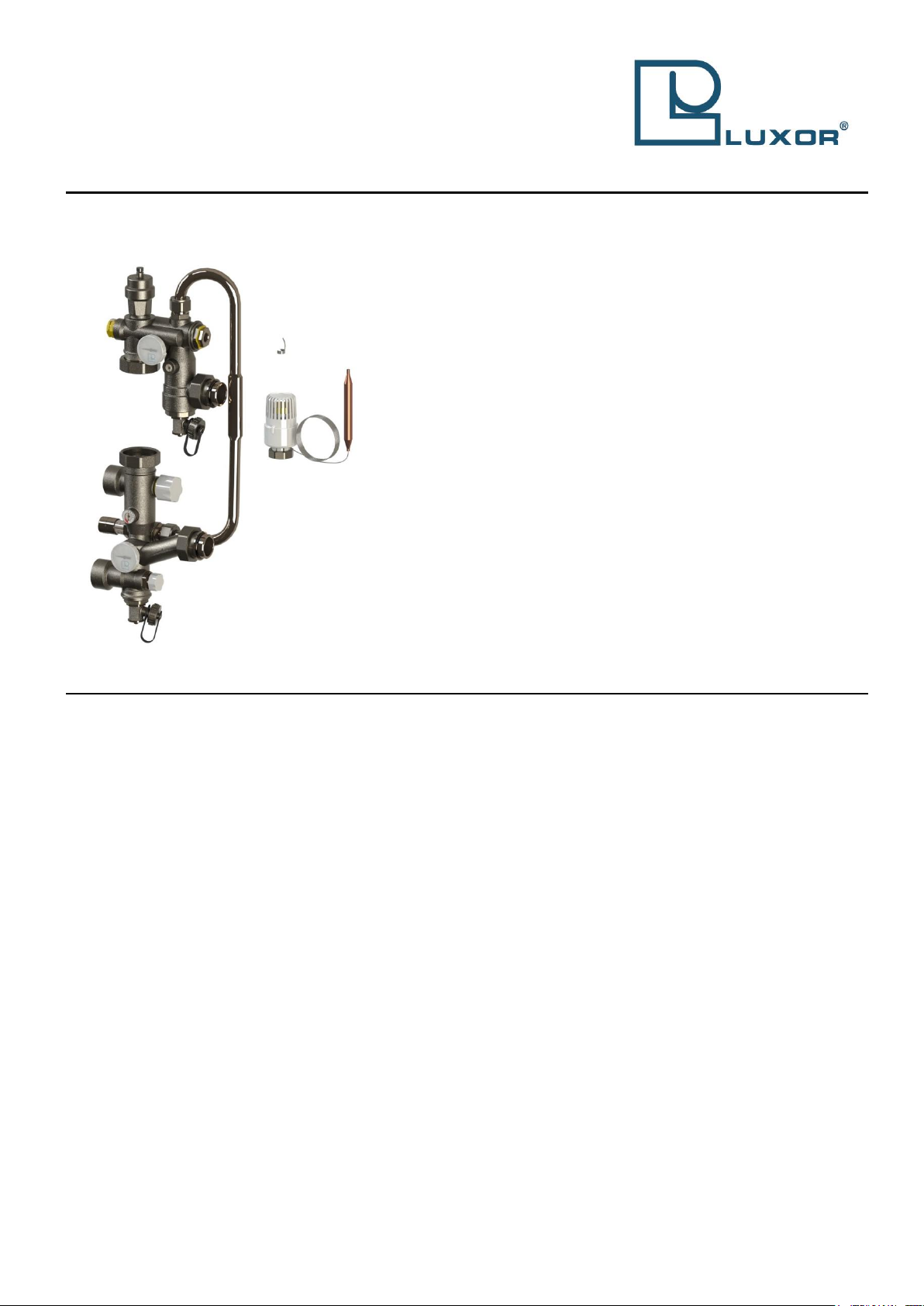
Mixing System
GM 1192
22/02/2018
Function
The mixing group GM 1192 is a regulation group which combines a
number of components in a single device able to maintain a pre-set
temperature in the radiant panels circuit of mixed heating systems. The
temperature in the panels is kept constant by a regulating valve which
mixes hot water coming from the boiler with the low temperature one
circulating in the panels. The GM 1192 can be connected directly to
Luxor manifolds for radiant panels by means of a G 1” male fitting with
soft seal. This makes the GM 1192 particularly convenient, since
it can be kept in stock as a modular component.
Moreover, the GM 1192 makes mixed heating systems extremely
flexible, since the regulation group can be adjusted to meet the future
requirements of the secondary circuit. It is therefore possible to expand
the radiant panels system simply by adding outlets, without temperature
or pressure issues downstream of the group.
The GM 1192 can be set both to increase the heating capacity
and to balance pressure drops.
Finally, thanks to its great regulation capacity, the GM 1192 allows to
make the secondary circuit independent from the primary in case of
replacement of important parts of the system, for example when a new
boiler with a different operating principle is installed. By means of the
bypass circuit, the circulation pump can keep on operating at design
conditions.
This type of system can supply a max thermal power of 20 kW with a
temperature of the primary circuit of ≥ 70°C.
Technical data
Max. working pressure:
6 bar
Max. differential pressure:
1 bar
Regulation range on the bypass:
0.2 ÷ 0.7 bar
Max. temperature on primary circuit:
80 °C
Max. working temperature on
secondary circuit:
70 °C
Temperature adjustment range on
secondary circuit:
20 ÷ 65 °C
Thermometer range:
0 ÷ 80 °C
Connections on primary circuit (to
boiler):
G 1” female
Connections to secondary manifold:
G 1” male
Adjustment range of therm. head:
20 ÷ 65 °C
Length of capillary:
2 m
Page 2

Materials
Mixing group
Body:
CW 617 N – DW UNI-EN 12165:2016
Obturator:
CW 614 N – DW UNI-EN 12164:2016
Gaskets:
Peroxide cured EPDM
Steel parts:
Stainless steel
Cap:
RAL9016 white ABS
Copper parts:
Nickel-plated annealed copper
Accessories
Brass parts:
CW 617 N – DW UNI-EN 12165:2016; CW 614 N – DW UNI-EN 12164:2016
Steel parts:
Stainless steel
Gaskets:
Peroxide cured EPDM
Safety valve:
Acetal
Thermostatic head
Head:
RAL9016 white ABS
Sensor:
Liquid
Thermometer
Case and stem:
Galvanised steel
Cover:
Transparent plastic material
Thermometric element:
Bimetallic spiral spring
Surface treatment
Nickel-plating
Page 3

Dimensional Drawings
GM 1192
Fixed point regulation group for floor heating systems, with
pump connection and thermostatic head.
GM 1193
Fixed point regulation group for floor heating systems with
pump connection.
Code
Size A B C D E Code
Size A B C D
E
72000050
G1”x130mm
130
120
200
495
G1”
72000052
G1”x130mm
130
120
200
495
G1”
72000055
G1”x180mm
180
120
250
495
G1”
72000057
G1”x180mm
180
120
250
495
G1”
Code
Size F G H L M Code
Size F G H L M 72000050
G1”x130mm
G1”1/2
G1”
M30x1.5
85
32
72000052
G1”x130mm
G1”1/2
G1”
M30x1.5
85
32
72000055
G1”x180mm
G1”1/2
G1”
M30x1.5
85
32
72000057
G1”x180mm
G1”1/2
G1”
M30x1.5
85
32
Construction
1. Thermostatic regulating valve (boiler
delivery) controlled by thermostatic
head with remote probe, 0-10V
electrothermal head or 3-point or 010V electric motor
2. Pump shut-off valve
3. Ball valve for pump interception and
balancing of the secondary circuit
4. Probe seat
5. Secondary circuit shut-off valve and
safety valve (boiler return)
6. Bypass valve
7. Automatic air vent valve
8. Water fill/drain tap
9. 3-piece union fittings with soft sealing
10. Fitting for circulation pump connection
11. Thermometers
12. Union fittings
13. Safety thermostat seat
Page 4

Flow Rate Diagram
Curve
Adjustment
Kv
1
ΔT=2 K
0.9
2
QM MAX
3.88
Page 5

Flow Rate Diagram
Curve
Adjustment
Kv
1
1/2
0.09
2
1
0.27
3
1+1/2
0.76
4
2
0.98
5
2+1/2
1.20
6
3
1.46
7
3+1/2
1.70
8
4
1.93
9
4+1/2
2.19
10
5
2.47
11
5+1/2
2.75
12
All open
3.01
Page 6

Working Instructions
The circulation of water through the secondary circuit radiant panels is activated by the
pump featured in the GM 1192, while the thermostatic head mounted on the
adjustment valve keeps the temperature of the water to be sent to the radiant panels
constant by acting on the quantity of hot water which is integrated into the secondary
circuit.
The water returning to the primary circuit flows through the lockshield valve upon which
it is possible to act in order to balance pressure drops. It is advisable to install a
security thermostat on the pump inlet valve in order to avoid damages caused by a
sudden temperature rise. The intervention of the thermostat must block the functioning
of the pump.
How to install the fixed point thermostatic head:
The GM 1192 system is supplied with a plastic cap protecting the control stem of the
adjustment valve. Remove the protection cap.
To ease the installation, set the thermostatic head to the maximum value and screw
it onto the valve.
Set the head to the desired temperature.
Place the bulb of the head into the fastening device.
Loosen the union fittings marked with “12” in the picture to ease the installation of
the pump.
Assemble the pump taking care to place it in the correct direction, which is upwards.
After the installation, tighten back the fittings “12”
The balancing ball valve “3” is adjusted by aligning the reference mark on the control
stem with the scale by means of a 4 mm hex wrench.
The bypass valve “6” is simply adjusted by turning the knob until the desired value.
To substitute the whole tightening device of the thermostatic screw while the group
is operating, proceed as follows:
o Remove the protection cap, manual knob, thermostatic head or thermoelectric
head;
o Hold the screw body with a 19 mm wrench and unscrew the tightening device
by means of a 9 mm wrench;
Page 7

o Replace the tightening device with the spare accessory and screw it by means
of a 9 mm wrench;
o Screw the protection cap, manual knob, thermostatic head or thermoelectric
head back.
To adjust the flow rate:
o Unscrew the ABS plug “A” where the gasket “B” is placed;
o Without forcing, use a 5 mm Allen key to close the obturator “C”;
o Open the obturator for a number of turns as indicated on the flow rate
diagram;
o Screw back the ABS plug “A”.
WARNING: Once the system has been leak tested, please relieve the pressure.
A differential pressure over 1 bar between the inlet and the outlet of the valve
may cause the sealing O-ring to be expelled.
Before starting the system it is important to check that:
o All union fittings marked with “12” are perfectly tightened;
o The check valve marked with “5” is completely open. To adjust the valve,
unscrew the brass plug and act on the obturator by means of a 5 mm hex
wrench.
The value shown by the thermostatic head is indicative, the temperature of the water
entering the radiant panels circuit can be read on the thermometer of the upper
group.
To avoid excessive noise in the system, do not use the thermostatic valve with ΔP
values higher than 0,5 bar.
Coupled with the pump PCE 755 art. 69011560, the GM 1192 system can be
installed in a cabinet with a 90 mm internal usable depth.
Luxor S.p.A.
Sede amministrativa, stabilimento e uffici commerciali:
via Madonnina, 94 – 25018 Montichiari - (BS) Italy
Administrative office, factory and commercial office:
Tel.: 030-9961161 – Fax: 030-9961165
info@luxor.it – www.luxor.it
Luxor si riserva il diritto di apportare miglioramenti e modifiche ai prodotti descritti ed ai relativi dati tecnici in qualsiasi momento e senza preavviso -
Luxor reserves the right to ameliorate and modify the above products and their technical data at any time and without notice
~
 Loading...