

Page 1
LUXOR
INSTRUCTION MANUAL For
Terrace & Patio Heater
0
MODEL NO. 2650, 2400
Please Retain manual for reference
Page 2
WARNING SAFETY RULES
PLEASE
If
1.
2.
3.
1.
2.
READ
THE
FOLLOWING
SAFETY
RULES
PRIOR
OPERATION
OF
THE
HEATER
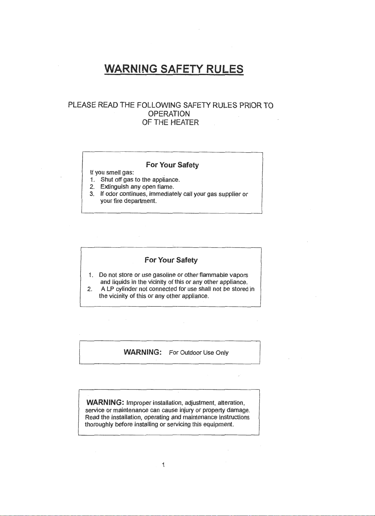
For
Your Safety
you
smell gas:
Shut off gas to the appliance.
Extinguish any open flame.
If
odor continues, immediately call your gas supplier or
your fire department.
For
Your Safety
Do not store
and liquids in the vicinity
A LP cylinder not connected for use shall not be stored in
the vicinity
or
use gasoline or other flammable vapors
of
this or any other appliance.
of
this or any other appliance.
TO
WARNING: For Outdoor Use Only
I
WARNING: Improper installation, adjustment, alteration,
service
Read the installation, operating and maintenance instructions
thoroughly before installing
or
maintenance can cause injury or property damage.
or
servicing this equipment.
1
Page 3
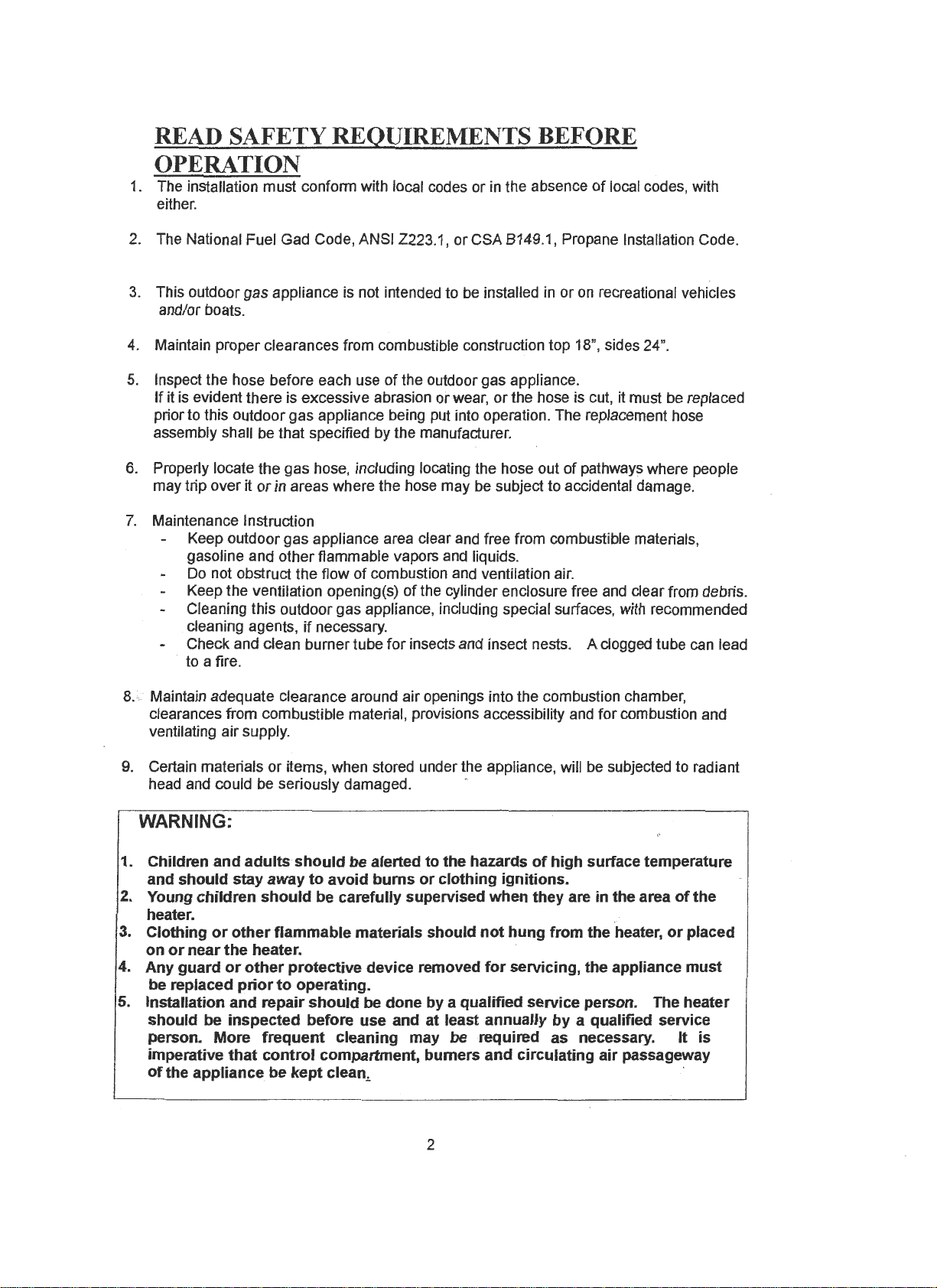
READ SAFETY REQUIREMENTS BEFORE
OPERATION
1.
The installation must confonn with local codes or
either.
2. The National Fuel Gad Code, ANSI Z223.1, or CSA 8149.1, Propane Installation Code.
3.
This outdoor gas appliance is not intended to be installed
and/or boats.
4.
Maintain proper clearances from combustible construction top 18", sides 24".
5.
Inspect the hose before each use
If
it is evident there is excessive abrasion or wear,
prior to this outdoor gas appliance being put into operation. The replacement hose
assembly shall be that specified by the manufacturer.
of
the outdoor gas appliance.
in
the absence
in
or
the hose is cut, it must be replaced
of
local codes, with
or
on
recreational vehicles
6. Properly locate the gas hose, including locating the hose out
or
may trip over it
7.
Maintenance Instruction
Keep outdoor gas appliance area clear and free from combustible materials,
gasoline and other flammable vapors and liquids.
Do
not obstruct the flow
Keep the ventilation opening(s)
Cleaning this outdoor gas appliance, including special surfaces, with recommended
cleaning agents,
Check and clean burner tube
to a fire.
in areas where the hose may be subject to accidental damage.
of
combustion and ventilation air.
of
the cylinder enclosure free and clear from debris.
if
necessary.
for
insects and insect nests. A clogged tube can lead
of
pathways where people
8. Maintain adequate clearance around air openings into the combustion chamber,
clearances from combustible material, provisions accessibility and for combustion and
ventilating air supply.
9.
Certain materials
head and could be seriously damaged.
or
items, when stored under the appliance, will be subjected to radiant
WARNING:
1. Children and
and should stay away
2.
Young children
heater.
3.
Clothing
or
near
on
4. Any guard
be replaced
5. Installation and repair
should be inspected before use and at least annually
person. More
imperative
of
the appliance be
or
adults
other
the
or
other
prior
that
should
should
be alerted
to
avoid
burns
or
be carefully supervised when they are in the area
flammable materials should
heater.
protective device removed
to
operating.
should
frequent
control
kept
be done by a qualified service person. The heater
cleaning may be required as necessary. It
compartment, burners and circulating
clean
...
to
the hazards
of
clothing ignitions.
not
hung from the heater,
for
servicing, the appliance
high surface temperature
or
by
a qualified service
air
passageway
of
the
placed
must
is
2
Page 4
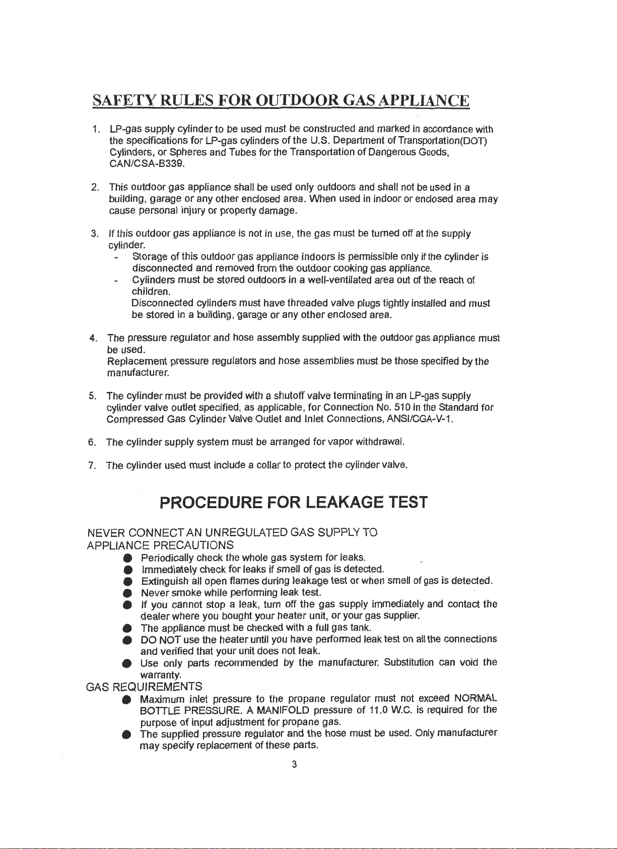
SAFETY RULES
1.
LP-gas supply cylinder to be used must be constructed and marked
the specifications
Cylinders,
CAN/CSA-8339.
2.
This outdoor gas appliance shall
building, garage
cause personal injury
3.
If
this outdoor gas appliance is not
cylinder.
4.
The pressure regulator and hose assembly supplied with the outdoor
be used.
Replacement pressure regulators and hose assemblies must be those specified by the
manufacturer.
or
Spheres and Tubes for the Transportation
or
Storage
disconnected and removed from the outdoor cooking gas appliance.
Cylinders must be stored outdoors
children. ·
Disconnected cylinders must have threaded valve plugs tightly installed and must
be stored in a building, garage
of
this outdoor gas appliance indoors is permissible only if the cylinder is
FOR
for
LP-gas cylinders
any other enclosed area. When used
or
property damage.
OUTDOOR GAS APPLIANCE
of
the U.S. Department
be
used only outdoors
in
use, the gas must
in
a well-ventilated area out of
or
any other enclosed area.
in
accordance with
of
Transportation(DOT)
of
Dangerous Goods,
and
shall not
in
indoor or enclosed area may
be
turned off at
be
used
the
supply
the
reach of
gas
appliance must
in
a
5.
The cylinder must be provided with a shutoff valve terminating
cylinder valve outlet specified, as applicable,
Compressed Gas Cylinder Valve Outlet and Inlet Connections, ANSI/CGA-V-1.
be
6. The cylinder supply system must
7.
The cylinder used must include a collar to protect the cylinder valve.
arranged
for
Connection
for
vapor withdrawal.
No.
in
an
510
PROCEDUREFORLEAKAGETEST
NEVER CONNECT AN UNREGULATED GAS SUPPLY
APPLIANCE PRECAUTIONS
e Periodically check the whole gas system
e Immediately check for leaks
if
smell
for
of
gas is detected.
e Extinguish all open flames during leakage test or when smell of
e
Never
smoke while performing leak test.
e
If
you cannot stop a leak, turn off the gas supply immediately
dealer
where you bought your heater unit,
or
e The appliance must be checked with a full gas tank.
e
DO
NOT
use the heater until you have performed leak test
and verified that your unit does not leak.
e Use only parts recommended by the manufacturer. Substitution can void the
warranty.
GAS REQUIREMENTS
e Maximum inlet pressure to the propane regulator must not exceed NORMAL
BOTTLE PRESSURE. A MANIFOLD pressure
purpose
of
input adjustment for propane gas.
e The supplied pressure regulator and the hose must
may
specify replacement of these parts.
TO
leaks.
your gas supplier.
on
of
11.0
W.C.
be
used. Only manufacturer
LP-gas supply
in
the
Standard
gas
is detected.
and
contact the
all
the connections
is required for the
for
3
Page 5

e The installation must conform with local codes
with either the National Fuel Gas Code., ANSI 2223.1 PROPANE
INSTALLATION CODE or GSA 8149.1.
e The appliance
propane gas tank. The propane tank is not included.
is
equipped with a hose assembly for hook-up to standard
e A dented, rusted or damaged propane tank may
checked
connection.
e The propane tank must be constructed and marked
specifications for
by
your tank supplier. Never use a propane tank with a damaged valve
LP
gas tanks
of
the US Department of Transportation (DOP).
or,
in
the
absence
be
hazardous and should
in
accordance with the
of
local codes,
be
e The propane tank must be arranged to provide for vapor withdrawal from the
operating
e Never connect
TESTING FOR LEAKAGE
Ga~
connections
mishandling
whole. A complete gas leakage test must be performed again at the installation site.
Please follow the procedure below for leakage test.
of
the appliance during the shipment might contribute to product integrity as a
e Make a soap solution
solution
appear where a leak
e Make sure the safety control valve is
gas
tank.
an
unregulated propane tank to the appliance.
on
the appliance are leak tested at the factory prior to shipment. Possible
of
one part liquid detergent and one part water. The soap
can
be
applied with a spray bottle, brush or rag. Soap bubbles with
is
present.
on
the "OFF" position.
e Turn ON the gas supply and check for bubbles from the hoses and connections.
Pressure of bubbles means that a leak path is present.
e
If
a leak
fitting, turn gas supply ON and recheck.
is
present, turn OFF the gas supply immediately, tighten any leaking
Visually Checking Burner Flames
The flame pattern at the emitter grid should be visually checked whenever the appliance
operated. The flame should
appliance should be burned off immediately and NOT operated again until repair are made.
When black soot accumulates
(see Figure 1.)
Propane
This appliance is designed to operate with a standard 20 lb propane tank with Type 1 cylinder
connection device (AGA Requirement 10-94). The propane tank must
Gas
Tank Size and Capacity (Tank not included with appliance)
be
blue with a yellow tip. Under following conditions the
on
the emitter grid.
Surface of
Emitter Grid
Distance from
electrode
to emitter is 4mm
Figure
1;
Normal Flame Position
be
provided with:
is
The gas
The cylinder must
tank.
(LP-gas supply cylinder) is not provided with the appliance.-
be
provided with a shutoff valve terminating in
4
an
LP-gas supply
Page 6

cylinder valve outlet specified, as-applicable, for Connection
Standard for Compressed Gas Cylinder Valve Outlet
and
No.
51 o in
Inlet Connections,
ANSI/CGA-V-1-1977.
gas
The
The
tank supply system must
gas
tank used must include a collar to protect the tank valve.
be
arranged for vapor withdrawal.
The outlet of the tank valve is 15/16 ACME male threaded specified in
cylinder connection device per AGA requirement 10-94 Standard.
The
tank valve is
designed to provide a positive sealing device for safety.
LP-gas supply cylinder to
with the specifications
Transportation (DOP)
for
or
used must
LP-gas cylinders (Gas
the National Standard of Canada. CAN/CSA-8339,
be
constructed and marked in accordance
Tank)
of
the
U.S.
Department of
be
Cylinders, Spheres and Tubes for the Transportation of Dangerous Goods.
be
The LP-gas supply cylinders valve/connection must
to
with the connection device attached
the inlet of the pressure regulator supplied
properly and safely mate
with the gas appliance.
Pressure
Regulator"-
Figure 2.: Gas Tank Connection
Type
Propane
Tank
the
1
TECHNICAL DATA & SPECIFICATION
It is about
Performance, connection-valve (consumption) and work-pressure is to
1 Base
2 Cylinder cover
3 Ventilation opening
4 ?ost
5 Gas control
6 Burner assembly
7 Flame screen
8 Reflector
an
terrace-radiator, that with liquid-gas (butane or propane) is driven.
appropriate at the appliance.
4
-------l
3
-----~
"---
2
I.
460
mm
be
taken of the label
E
E
0
<Il
N
N
, I
5
Page 7

A.
Construction-Characteristics
Transportable terraces-radiator with column.
Color : As order
Casings : Varnished steel-sheet metal-casing.
The main gas flow is opened over the service-valve as well as is closed, the entire gas flow is
closed over the gas valve at the gas bottle as well as is opened.
of
The burner is provided from stainless steel. It emits the heat with help
infrared-area from above.
B.
Specification
- For outdoor use only.
- Use for "PROPANE" only.
- Max. wattage:
- Min. wattage:
- Height: 2260
C.
Table
of
Orifice :
Model
Model
mm
Gas Pressure
2650, 2500/45.000 BTU
2650, 2400/25.000 BTU
with free stand.
"W.C.
11
Main orifice
Diameter in
(for #2650, 2400)
mm
1.9
the reflector in
the
HEATER STAND & LOCATION
BE
CAREFUL
UNDER THIS SPACE HEATER, WHILE
SUBJECTED TO RADIANT HEAT AND COULD BE SERIOUSLY DAMAGED
WHEN
CERTAIN MATERIALS,
IN
OR
ITEMS, ARE LEFT
USE, THEY WILL BE
+ The heater is primarily
patios, decks, spas pool and working areas.
for
heating of outdoor
24
•
+ Always ensure that adequate fresh air ventilation
is provided. Follow the spacing tolerance in Figure 1.
+ The minimum clearances to combustible construction,
shown in Figure 1, must be maintained at all times.
+ The installation must conform to local codes, or in the
absence
local codes, with ANSI Z223
or
CSA B149.1.
of
+ The heater must be placed on level firm ground:
+ Keep away from areas where gasoline or other
or
flammable liquids
Important hints
The appliance is to be anchored solidly with enclosed brackets and screws.
Fixing screws: 6 pes
(Without knowing which material of ground that this
apparatus will be applied, the fixing screws are
usually excluded, please consult with your hardware
suppliers to get proper screws before grounding.)
Under strong wind turn the heater off, close propane cylinder and remove the heat reflector.
The appliance should not be transported in hot condition as well as during operation. It must
be turned off and allowed to cool.
vapors are stored or used.
to
workings
of
the appliance:
z.,
~h.
6
Page 8

ASSEMBLING INSTRUCTION FOR WHEEL
(1)
Screw ------------- 8
(2)
Nut ----------------- 2
(3)
Wheel------------ 2
(4)
Bracket ---------- 2
(5)
Bolt --------------- 2
(6)
Base
-------------- 1
(7)
Nut--------------8 pes
(8)
Screw ------------ 8
(9)
Bracket
(1
0)
Nut--------------- 8
--------
2
pes
pes
pes
pes
pes
pes
pes
pes
pes
ASSEMBLING PROCEDURE for Model 2650, 2400
STEP
1:
1-1
Put the 3-pcs post bracket
position of cylinder
1-2 Screw in the 3
the bracket cylinder assembly
1-3 Tighten each
pes
of
the bolts.
onto
each
base
as
shown.
of M8x15mm bolt
on
STEP 2:
2-1
Put the post
bracket assembly
2-2 Screw
bolt and M6-nut
2-3 Tighten
in
each
on
the 6
top
of 3-pcs post
as
pes
of
pairs
of
the
shown.
M6x35mm
through
bolt nut pairs.
STEP
3:
3-1
Put the tank housing through the post
shown.
'
as
.7
Page 9

Fig.1
F"
.
IQ .......
2
.
Page 10

STEP
4:
4-1
Put hose connector nut side from
of
post
and
bottom
the top.
4-2 Have burner upside down and fit
the hose connector nut onto the
burner gas inlet connector
4-3 Fix the burner base vertically with
post and install 4
bolt. Tighten each of the bolts.
STEPS
5-1
Put reflector canopy onto the top
burner aligning through the 3 supporting bolts
5-2 After placing the reflector canopy,
place 3
5-3 Tighten each
pes
go through it to
pes
of
of
castle nuts
of
the bolts.
as
shown.
M6x1
Omm
on
the supporting bolts.
OPERATION
Turn ON
1.
Push the knob
2.
At same time Press the igniter until the flame comes
3.
Release the knob and check
above.
4. Release the knob and tum it to the max. temperature full counter-clockwise.
Turn OFF
1.
Turn the knob clockwise to the stop position.
2. Depress knob and tum clockwise to shut
Warning:
A 5-minute complete shutoff period before the appliance
and
turn counter-clockwise 90°, and hold to it.
if
the flame stays
on
off
the valve from the gas cylinder completely.
8
on.
the burner,
is
relighted.
if
goes out, repeat (2)
as
oFF
G\0
LO
~HI
IGNITER
0
Page 11

STORAGE AND CLEANING
1. Close the propane cylinder valve.
2. Disconnect the regulator from the propane cylinder.
3. Store the propane cylinder outside as per the propane storage and handling code
58
ANSI!NFPA
or CSA B149 .2
CLEANING
Wipe off surfaces with soft moist rag using only suitable cleaners such
Scratching and sharp cleaners.
AND
CARE
PROBLEMS CHECK LIST
PROBLEMS
1 . Burner not stay
2. Burner not light
on
on
PROBABLECAUSE
- Gas valve may
- Tank fuel empty
- Orifice blocked
- Loose connection
- Thermocouple bad
- Gas leak in line
of
- Lack
- Pressure is low
- Orifice blocked
- Control not
- Thermocouple
fuel pressure
ON
be
bad
OFF
SOLUTION
- Turn the gas valve ON
- Refill LPG tank
- Clean
- Check all fittings
- Replace the Therrnocouple
- Check connections
- Near empty
- Tank is near empty
- Remove and clean it
- Tum valve to
- Replace the Thermocouple
as
soapy water.
or
replace orifice
fuel
tank
ON
3. Ignitor couldn't work -Electrode might have
accumulated black soot
AMERICAN
HEATING
4524
LOS
ANGELES,
TECHNOLOGIES
BRAZIL
TEL: 877-447-4554
www
. LuxorGrills. com
9
ST
CA
-
90039
Light
the burner by
or CLEAN out the black soot
and re-ignite.
GAS
GUN
INC.
 Loading...