

Luxon Video TVR series User Manual

Digital Video Recorder
User Manual

User Manual of Digital Video Recorder
2
User Manual
About this Manual
This Manual is applicable to TVI series DVR.
The Manual includes instructions for using and managing the product. Pictures, charts, images and all other
information hereinafter are for description and explanation only. The information contained in the Manual is
subject to change, without notice, due to firmware updates or other reasons. Please find the latest version in the
company website
Please use this user manual under the guidance of professionals.
Legal Disclaimer
REGARDING TO THE PRODUCT WITH INTERNET ACCESS, THE USE OF PRODUCT SHALL BE
WHOLLY AT YOUR OWN RISKS. OUR COMPANY SHALL NOT TAKE ANY RESPONSIBILITES F OR
ABNORMAL OPERATION, PRIVACY LEAKAGE OR OTHER DAMAGES RESULTIN G FROM CYBER
ATTACK, HACKER ATTACK, VIRUS INSPECTION, OR OTHER INTERNET SECURITY RISKS;
HOWEVER, OUR COMPANY WILL PROVIDE TIMELY TECHNICAL SUPPORT IF REQUIRED.
SURVEILLANCE LAWS VARY BY JURISDICTION. PLEASE CHECK ALL RE LEVANT LAWS IN YOUR
JURISDICTION BEFORE USING THIS PRODUCT IN ORDER TO ENSURE THAT YOUR USE
CONFORMS THE APPLICABLE LAW. OUR COMPANY SHALL NOT BE LIABLE IN THE EVENT THAT
THIS PRODUCT IS USED WITH ILLEGITIMATE PURP OSES.
IN THE EVENT OF ANY CONFLICTS BETWEEN THIS MANUAL AND THE APPLICABLE LAW, THE
LATER PREVAILS.

User Manual of Digital Video Recorder
3
Regulatory Information
FCC Information
FCC compliance: This equipment has been tested and found to comply with the limits for a Class A digital
device, pursuant to part 15 of the FCC Rules. These limits are designed to provide reasonable protection against
harmful interference when the equip ment is operated in a commercial environ ment. This equip ment generates,
uses, and can radiate radio frequency energy and, if not installed and used in accordance with the instruction
manual, may cause harmful interference to radio communications. Operation of this equipment in a residential
area is likely to cause harmful interferen ce in which case the user will be requ ired to correct the interferen ce at
his own expense.
FCC Conditions
This device co mplies with part 15 of the FCC Rules. Operation is subject to the following two conditions:
1. This device may not cause harmful interference.
2. This device must accept any interf er ence received, including i nt er ference that may cause undesired operation.
EU Conformity Statement
This product and - if app licable - the supplied accessories too are marked with "CE" and comply
therefore with the applicable harmonized European standards listed under the EMC Directive
2004/108/EC, the RoHS Directive 2011/65/EU.
2012/19/EU (WEEE directive): Products marked with this symbol cannot be disposed of as
unsorted municipal waste in the European Union. For proper recycling, return this product to your
local supplier upon the purchase of equivalent new equipment, or dispose of it at designated
collection points. For more information see: www.recyclethi s.info
2006/66/EC (battery directive): This product contains a battery that cannot be disposed of as
unsorted municipal waste in the European Union. See the product documentation for specific
battery information. The battery is marked with this symbol, which may include lettering to
indicate cadmium (Cd), lead (Pb), or mercury (Hg). For proper recycling, return the battery to your supplier or
to a designated collection point. For more information see: www.recyclethi
Industry Canada ICES-003 Compliance
This device meets the CAN ICES -3 (A)/NMB-3(A) standards requirements.
s.info

User Manual of Digital Video Recorder
4
Safety Instruction
These instructions are intended to ensure that user can use the product correctly to avoid danger or property loss.
The precaution measure is divided into “Warnings” and “Cautions”
Warnings: Serious injury or death may occur if any of the warnings are neglected.
Cautions: Injury or equipment damage may occur if any of the cautions are neglected.
Warnings
Proper configuration of all passwords and o ther security settings is the responsibility of the installer
and/or end-user.
In the use of the product, you must be in strict compliance with the electrical safety regulations of the
nation and region. Please refer to technical specifications for detailed information.
Input voltage should meet both the SELV (Safety Extra Low Voltage) and the Limited Power Source
with 100~240 VAC or 12 VDC according to the IEC60950-1 standard. Please refer to technical
specifications for detailed information.
Do not connect several devices to one power adapter as adapter overload may cause over-heating or a
fire hazard.
Please make sure that the plug is firmly connected to the power socket.
If smoke, odor or noise rise from the device, turn off the power at once and unplug the power cable,
and then please contact the service center.
Warnings
Follow these
safeguards to prevent serious
injury or death.
Cautions
Follow these precautions
to prevent potential injury or
material damage.

User Manual of Digital Video Recorder
5
Preventive and Cautionary Tips
Before connecting and operating your device, please be advised of the following tips:
• Ensure unit is installed in a well-ventilated, dust-free environment.
• Unit is designed for indoor use only.
• Keep all liquids away from the device.
• Ensure environmental co nditions meet factory specifications.
• Ensure unit is properly secured to a rack or shelf. Major shocks or jolts to the unit as a result of dropping it
may cause damage to the sensitive electronics within the unit.
• Use the device in conjunction with an UPS if possible.
• Power down the unit before connecting and disconnecting accessories and peripherals.
• A factory recommended HDD should be used for th is device.
• Improper use or replace ment of the battery may result in hazar d of explosion. Replace with the same or
equivalent type only. Dispose of used batteries according to the instructions provided by the battery
manufacturer.

User Manual of Digital Video Recorder
6
Thank you for purchasing our product. If there is any question or request, please do not hesitate to contact dealer.
The figures in this manual are for reference only.
Product Key F eat ures
General
Connectable to HD-TVI and analog cameras;
Connectable to the Coaxitron camera/dome with long transmission distance;
Connectable to IP cameras;
Each channel support up to 720P resolution.
Independent configuration for each channel, including resolution, frame rate, bit rate, image quality,
etc.
Encoding for both video stream and video & audio stream; audio and video synchronization during
composite stream encoding;
Wat ermark technology.
Local Monitoring
HDMI/VGA output at up to 1920*1080 resolution;
1/4/6/8/9/16 screen live view is supported, and the display sequence of screens is ad justable;
Live view screen can be switched in group and manual switch and au tomatic cycle live view are also
provided, the interval of automatic cycle can be adj usted;
Quick setting menu is provided for live view;
The selected live view channel can be shielded;
Motion detection, video-tampering detection, vid eo exceptio n alarm, vi deo lo ss alar m and VCA alarm
functions;
Privacy mask;
Several PTZ protocols supported; PTZ preset, patrol and pattern;
Zooming in/out by clicking the mouse and PTZ tracing by dragging mouse.
HDD Manage ment
1 SATA hard disk can be connected; (Each disk with a maximum of 6TB storage capacity.)
8 network disks (NAS /IP SAN disks) can be connected;
Support S.M.A.R.T. and bad sector detection;
Support HDD sleeping function;
HDD property: redundancy, read-only, read/write (R/W);
HDD group management;
HDD quota management; different capacity can be assigned to different channels.
Recording and Playback
Holiday recording schedule configuration;
Cycle and non-cycle record ing modes;
Normal and event video encoding paramet er s ;
Multiple recording types: manual, continuous, alarm, motion, motion | alarm, motion & alarm;
8 recording time periods with separated recording types;
Pre-record and post-reco rd for motion detection triggered recording, and p re-record time for schedule
and manual recording;
Searching record files by events (alarm input/motion detection);

User Manual of Digital Video Recorder
7
Customization of tags, searching and playing back by tags;
Locking and unlocking of record f i le s;
Local redundant recording;
Searching and playing back record files by camera number, recording type, s tart time, end time, etc.;
Smart playback to go through less effective infor mation;
Zooming in for any area when playback;
Reverse playback of multi-channel;
Supports pause, fast forward, slow forward, skip forward, and skip backward when playback, locating
by dragging the mouse on the progress bar;
4/8/16-ch synchronous playback at 1080P.
Backup
Export data by a USB, SATA;
Export video clips when playback;
Management and maintenance of backup devices.
Alarm and Exception
Configurable arming time of alarm input/output;
Alarm for video loss, motion detection, video tampering, abnormal signal, video input/recording
resolution mismatch, illegal login, network disconnected, IP confliction, record exception, HDD erro r,
and HDD full, etc.;
Alarm triggers full screen monitoring, audio alarm, notifying sur veillance center, sending email and
alarm output;
VCA detection alarm (line crossing detection and intrusion detection) is supported;
Support coaxial alarm;
Automatic restore when s ystem is abnormal.
Other Local Functions
Manual and automatic video quality diagnostics;
Users can operate by mouse and remote control;
Three-level user management; admin user can create many operating account and define their
operating permission, which includes the permission to access any channel;
Completeness of operation, alarm, exceptions and log writing and searching;
Manually triggering and clearing alarms;
Importing and exporting of configuration file of devices;
Getting cameras type information automatically.
Network Functions
1 self-adaptive 10M/100M network interface
IPv6 is supported;
TCP/IP protocol, PPPoE, DHCP, DNS, DDNS, NTP, SADP, SMTP, SNMP, NFS, iSCSI, UPnP™ and
HTTPS are supported;
Extranet access by HiDDNS;
Support access by Cloud P2P;
TCP, U DP and RTP for unicast;
Auto/Manual port mapping by UPnP
TM
;
Remote search, playback, download, locking and unlocking the record files, and downloading files
broken transfer resume;
Remote parameters setup; remote import/export of device par ameters;
Remote viewing of the device status, system logs and alarm status;

User Manual of Digital Video Recorder
8
Remote keyboard operation;
Remote locking and unlocking of control panel and mouse;
Remote HDD formatting and program upgrading;
Remote system restart and shutdown;
Support upgrading via remote FTP server;
RS-485 transparent channel transmissio n;
Alarm and exception information can be sent to the remote host;
Remotely start/stop recording;
Remotely start/stop alarm output;
Remote PTZ control;
Remote JPEG capture;
Two-way audio and voice broadcasting;
Embedded WEB server.
Development Scalability
SDK for Windows and Linux system;
Source code of application software for demo;
Development support and training for application system.

User Manual of Digital Video Recorder
9
Table of Contents
Product Key Features ................................................................................................................................. 6
Chapter 1 Introduction .................................................................................................................................. 12
1.1 Front Panels ................................................................................................................................... 13
1.2 IR Remote Control Operations ...................................................................................................... 17
1.3 USB Mouse Operation .................................................................................................................. 19
1.4 Input Method Description .............................................................................................................. 20
1.5 Rear Panel ..................................................................................................................................... 21
Chapter 2 Getting Started ............................................................................................................................. 23
2.1 Starting Up and Shutting Down the DVR ..................................................................................... 24
2.2 Using the Wizard for Basic Configuration..................................................................................... 26
2.3 Adding and Connecting the IP Cameras ........................................................................................ 29
Chapter 3 Live View ...................................................................................................................................... 32
3.1 Intr o duction of Live View ............................................................................................................. 33
3.2 Operations in Live View Mode ...................................................................................................... 34
3.2.1 Front Panel Oper a ti on .......................................................................................................... 34
3.2.2 Using the Mous e in Live View ............................................................................................. 35
3.2.3 Using an Auxiliary Monitor ................................................................................................. 35
3.2.4 Main/Aux Output Switchi ng ................................................................................................ 36
3.2.5
Quick Setting Toolbar in Live View Mode .......................................................................... 36
3.3 Channel-zero Encoding ................................................................................................................. 38
3.4 Adjusting Live View Settings ........................................................................................................ 39
3.5 Manual Video Quality Diagnostics ................................................................................................ 41
3.6 User Logout ................................................................................................................................... 42
Chapter 4 PTZ Controls ................................................................................................................................ 43
4.1 Config uring PTZ Settings .............................................................................................................. 44
4.2 Setting PTZ Presets, Patrols & Patterns......................................................................................... 45
4.2.1 Customizing Presets ............................................................................................................. 45
4.2.2 Calling Presets ..................................................................................................................... 45
4.2.3 Customizing Patrols ............................................................................................................. 46
4.2.4 Calling Patrols ..................................................................................................................... 47
4.2.5 Customizing Patterns ........................................................................................................... 48
4.2.6 Calling Patterns .................................................................................................................... 48
4.2.7 Customizing Linear Scan Limit ........................................................................................... 49
4.2.8 Calling Linear Scan ............................................................................................................. 50
4.2.9 One-touch Park .................................................................................................................... 50
4.3 PTZ Control Panel ......................................................................................................................... 52
Chapter 5 Recording Settings ....................................................................................................................... 53
5.1 Configuring Recording Parameters ............................................................................................... 54
5.2 Configuring Record Schedule ....................................................................................................... 57
5.3 Configuring Motion Detection Record .......................................................................................... 60
5.4 Conf iguring Alarm Trigge red Record ............................................................................................ 61

User Manual of Digital Video Recorder
10
5.5
Configuring Manual Record .......................................................................................................... 62
5.6 Configuring Holiday Record ......................................................................................................... 63
5.7 Configuring Redundant Recording ................................................................................................ 65
5.8 Configuring HDD Group for Recording ........................................................................................ 67
5.9 Files Protecti on .............................................................................................................................. 68
Chapter 6 Playback ........................................................................................................................................ 70
6.1 Playing Back Record Files ............................................................................................................ 71
6.1.1 Playing Back by Channel ..................................................................................................... 71
6.1.2 Playback by Time................................................................................................................. 72
6.1.3 Playing Back by Event Search ............................................................................................. 74
6.1.4 Playing Back by Tag ............................................................................................................ 77
6.1.5 Playing Back by Smart Search ............................................................................................. 79
6.1.6 Playing Bac k by System Logs ............................................................................................. 80
6.1.7 Playing Back External File .................................................................................................. 81
6.2 Auxiliary Functions of Playback ................................................................................................... 82
6.2.1 Playing Back Frame by Frame ............................................................................................. 82
6.2.2 Smart Search ........................................................................................................................ 82
6.2.3 Digital Zoom ........................................................................................................................ 83
6.2.4 Reverse Playback of Multi-channel ..................................................................................... 84
Chapter 7 Backup .......................................................................................................................................... 85
7.1 Backing up Record Files ............................................................................................................... 86
7.1.1 Backing up by Normal Video Search ................................................................................... 86
7.1.2 Backing up by Event Search ................................................................................................ 87
7.1.3 Backing up Video Clips ....................................................................................................... 90
7.2 Managing Backup Devices ............................................................................................................ 92
Chapter 8 Alarm Settings .............................................................................................................................. 95
8.1 Setting Motion Detection............................................................................................................... 96
8.2 Setting Sensor Alarms ................................................................................................................... 98
8.3 Detecting V ideo Loss..................................................................................................................... 98
8.4 Detecting V ideo Tampering ......................................................................................................... 101
8.5 Detecting VCA Alarm ................................................................................................................. 103
8.6 Setting A ll-day Video Quality Diagnostics .................................................................................. 105
8.7 Handling Exceptions ................................................................................................................... 107
8.8 Setting A larm Response Actions ................................................................................................. 109
8.9 Triggering or Clearing Alarm Output Manually .......................................................................... 109
Chapter 9 Network Settings ......................................................................................................................... 111
9.1 Configuring General Settings ...................................................................................................... 112
9.2 Conf iguring Adva nced Settings ................................................................................................... 113
9.2.1 Configuring Extranet Access ............................................................................................. 113
9.2.2 Configuring PPPoE Settings .............................................................................................. 115
9.2.3 Configuring NTP Server .................................................................................................... 115
9.2.4 Configuring SNMP ............................................................................................................ 116
9.2.5 Configuring NAT ............................................................................................................... 117
9.2.6 Configuring More Settings................................................................................................. 118

User Manual of Digital Video Recorder
11
9.2.7
Configuring Email ............................................................................................................. 119
9.3 Checking Network Traffic ........................................................................................................... 121
9.4 Configuring Network Detection .................................................................................................. 122
9.4.1 Tes ting Network Delay and Packet Loss ............................................................................ 122
9.4.2 Exporting Network Packet ................................................................................................. 122
9.4.3 Checking Network Status .................................................................................................. 124
9.4.4 Checking Network Statistics .............................................................................................. 125
Chapter 10 HDD Manage ment............................................................................................................ 126
10.1 Initializing HDDs ........................................................................................................................ 127
10.2 Managing Network HDD ............................................................................................................ 129
10.3 Managing eSATA ........................................................................................................................ 130
10.4 Managing HDD Group ................................................................................................................ 130
10.4.1 Setting HDD Groups .......................................................................................................... 130
10.4.2 Setting HDD Property ........................................................................................................ 132
10.5 Configuring Quota Mode............................................................................................................. 134
10.6 C hecking HDD Status ................................................................................................................. 135
10.7 Checking S.M.A.R.T Information ............................................................................................... 136
10.8 Detecting Bad Sector ................................................................................................................... 137
10.9 Configuring HDD Error Al arms .................................................................................................. 138
Chapter 11 Camera Settings ............................................................................................................... 139
11.1 Configuring OSD Settings ........................................................................................................... 140
11.2 Configuring Priv acy Mask........................................................................................................... 141
11.3 Configuring Video Parameter s .................................................................................................... 143
Chapter 12 DVR Management and Maintenance ............................................................................. 144
12.1 Viewing System Information ....................................................................................................... 145
12.2 Searchi ng and Exporting Lo g Files ............................................................................................. 145
12.3
Importing/Exporting IP Camera Info ........................................................................................... 147
12.4 Importing/Exporting Configuration Files .................................................................................... 148
12.5 Upgrading System ....................................................................................................................... 149
12.5.1 Upgrading by Local Backup Device .................................................................................. 149
12.5.2 Upgrading by FTP ............................................................................................................. 149
12.6 Restoring Default Settings ........................................................................................................... 150
Chapter 13 Others ................................................................................................................................ 151
13.1 Configuring RS-232 Serial Port................................................................................................... 152
13.2 Configuring General Settings ...................................................................................................... 153
13.3 Configuring DST Settings ........................................................................................................... 154
13.4 Configuring More Settings .......................................................................................................... 155
13.5 Managing User Accounts............................................................................................................. 156
13.5.1 Adding a User .................................................................................................................... 156
13.5.2 Deleting a User .................................................................................................................. 158
13.5.3 Editing a User .................................................................................................................... 159
Appendix 160
Glossary ................................................................................................................................................. 161
Troubleshooting ..................................................................................................................................... 162

User Manual of Digital Video Recorder
12
Chapter 1 Introduction
User Manual of Digital Video Recorder
13
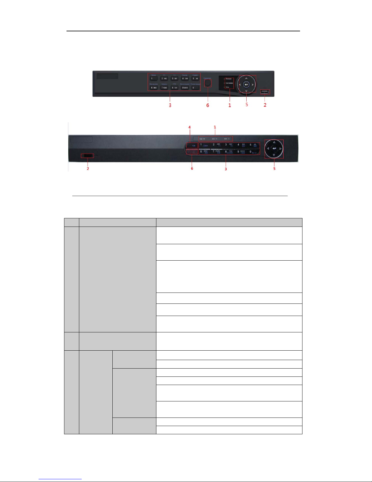
1.1 Front Panels
4CH/8CH
16CH
Figure 1. 1 Front Panel of 4ch/8ch/16ch TVI DVR
Table 1. 1 Description of Front Panel
No. Name Function Description
1
Status Indicators
POWER: the POWER indicator turns green when NVR is powered
up.
READY: The indicator light is green when the device is running
normally.
STATUS: 1.The light is green when the IR remote control is
enabled; 2.The light is red when the function of the composite keys
(SHIFT) are used; 3. The light is out when none of the above
condition is met/
ALARM: the light is red when there is an alarm occurring.
HDD: the indicator flickers red when HDD is reading/writing.
Tx/Rx: TX/RX indicator flickers green when network connection is
functioning normally.
2 USB Interfaces
Universal Serial Bus (USB) ports for additional devices such as
USB mouse and USB Hard Disk Drive (HDD).
3
Composite
Keys
1/MENU:
Enter numeral “1”;
Access the main menu in terface.
2/ABC/F1:
Enter numeral “2”;
Enter letters “ABC”;
The F1 button when used in a list field will select all items in the
list.
In PTZ Control mode, it will turn on/off PTZ light and when the
image is zoomed in, the key is used to zoom out.
3/DEF/F2:
Enter numeral “3”;
Enter letters “DEF”;

User Manual of Digital Video Recorder
14
No. Name Function Description
The F2 button is used to change the tab pages.
In PTZ control mode, it zooms in the image.
4/GHI/ESC:
Enter numeral “4”;
Enter letters “GHI”;
Exit and back to the previous menu.
5/JKL/EDIT:
Enter numeral “5”;
Enter letters “JKL”;
Delete characters before cursor;
Check the checkbox and select the ON/OFF switch;
Start/stop record clipping in playback.
6/MNO/PLAY:
Enter numeral “6”;
Enter letters “MNO”;
Playback, for direct access to playback interface.
7/PQRS/REC:
Enter numeral “7”;
Enter letters “PQRS”;
Open the manual record int erface.
8/TUV/PTZ:
Enter numeral “8”;
Enter letters “TUV”;
Access PTZ control in terface.
9/WXYZ/PR
EV:
Enter numeral “9”;
Enter letters “WXYZ”;
Multi-channel display in live view.
0/A:
Enter numeral “0”;
Shift the input methods in the editing text field. (Upper and
lowercase, alphabet, symbols or numeric input).
Double press the button to switch the main and auxiliary output.
4 SHIFT
Switch between the numeric or letter input and functions of the
composite keys. (Input letter or numbers when the light is out;
Realize functions when the light is red.)
5 Control Buttons
Directional buttons:
In menu mode, the direction buttons are used to navigate between
different fields and items and s elect setting parameters.
In playback mode, the Up and Down buttons are used to speed up
and slow down record playing, and the Left and Right buttons are
used to move the recording 30s forwards or backwards.
In the image setting interface, the up and down button can adjust
the level bar of the image parameters.
In live view mode, these buttons can be used to switch channels.
Enter:
The Enter button is used to confirm selection in menu mode; or
used to check checkbox fields and ON/OFF switch.
In playback mode, it can be used to play or pause the video.
In single-frame play mode, pressing the En ter button will play the
video by a single frame.
And in auto sequence view mode, the buttons can be used to pause
or resume auto sequence.
User Manual of Digital Video Recorder
15
No. Name Function Description
6 IR Receiver
Receiver for IR remote.
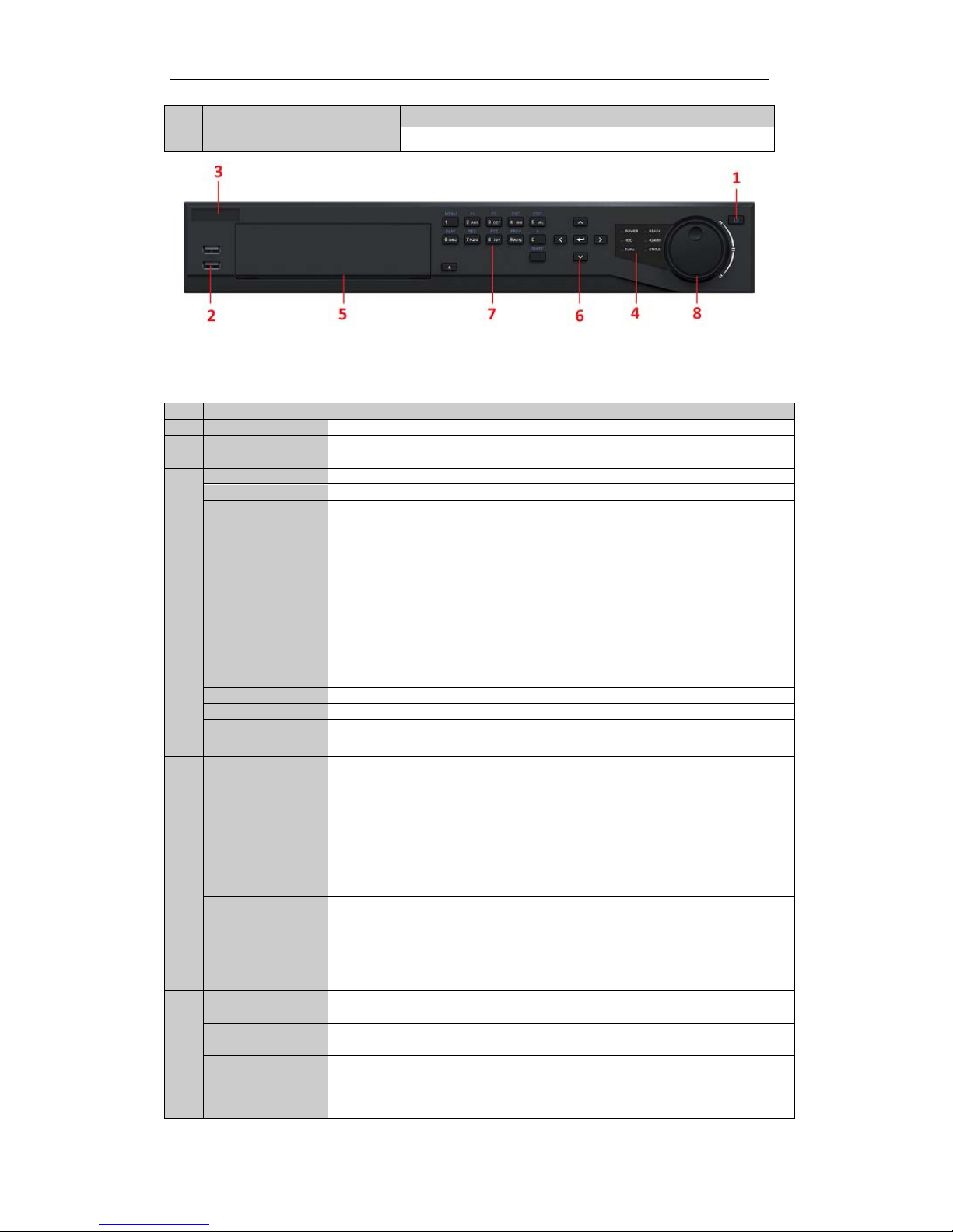
Figure 1. 2 Front Panel of 32ch TVI DVR
Table 1. 2 Description of Front Panel
No.
Name
Function Description
1
POWER ON/OFF
Power on/off switch.
2
USB Interface
Connect to USB mouse or USB flash memory.
3
IR Receiver
Receiver for IR remote con trol devices.
4
POWER
Power indicator lights in green when DVR is powered up.
READY
Ready indicator is normally green, indicating that the DVR is functioning properly.
STATUS
Indicator turns green when DVR is controlled by an IR remote control with the
address from 1~254;
Indicator turns red when the SHIFT button is used;
Indicator does not light when the DVR is controlled by a keyboard or by the IR
remote control with the address of 255;
Indicator turns green when the DVR is controlled by IR remote control (with the
address from 1~254) and keyboard at the same time , and the SHIFT button is not
used;
Indicator turns orange : (a) when the DVR is controlled by IR remote control (with
the address from 1~254) and keyboard at the same time and the SHIFT button is used
as well; (b) when the DVR is controlled by IR remote control (with the address from
1~254) and the SHIFT button is used.
ALARM
Alarm indicator turns red when a sensor alarm is detected.
HDD
HDD indicator blinks in red when data is being read from or written to HDD.
Tx/Rx
TX/RX indictor blinks in green when network connection is functioning properly.
5
DVD-ROM
Slot for DVD-ROM.
6
DIRECTION
The DIRECTION buttons are used to navigate between different fields and items in
menus.
In Playback mode, the Up and Down button is used to speed up and slow down
recorded video.
In All-day Playback mode, the Left/Right button can be used to select the reco r ded
video of next/previous day; in Playback by Normal Video Search, the Left/Right
button can be used to select the next/previous recorded file.
In Live View mode, the directional buttons can be used to cycle through channels.
In PTZ control mode, it can control the movement of the PTZ camera.
ENTER
Confirm selection in any of the menu modes. It can also be used to tick checkbox
fields.
In Playback mode, it can be used to play or pause the video.
In Single-frame Playback mode, pressing the ENTER button will advance the video
by a single frame.
In Auto-switch mode, it can be used to stop /start auto switch.
7
SHIFT Switch of compound keys between the numeric/letter input and functional control.
1/MENU
Enter numeral “1”;
Access the main menu in terface.
2ABC/F1
Enter numeral “2”;
Enter letters “ABC”;
The F1 button can be used to select all items on the list;
In PTZ Control mode, the F1 button can be used to zoom out (zoom-) the PTZ

User Manual of Digital Video Recorder
16
camera;
In live view or playback mode, the F1 button can be used to switch between main
and spot video output.
3DEF/F2
Enter numeral “3”;
Enter letters “DEF”;
In PTZ Control mode, the F1 button can be used to zoom in (zoom+) the PTZ
camera;
The F2 button can be used to cycle through tab pages.
4GHI/ESC
Enter numeral “4”;
Enter letters “GHI”;
Exit and back to the previous menu.
5JKL/EDIT
Enter numeral “5”;
Enter letters “JKL”;
Delete characters before cursor;
Select the checkbox and ON/OFF switch;
Start/stop record clipping in playback.
6MNO/PLAY
Enter numeral “6”;
Enter letters “MNO”;
In Playback mode, it is used for direct access to pl ayback interface.
7PQRS/REC
Enter numeral “7”;
Enter letters “PQRS”;
Manual record, for direct access to manual record interface; manually enable/disable
record.
8TUV/PTZ
Enter numeral “8”;
Enter letters “TUV”;
Access PTZ control in terface.
9WXYZ/PREV
Enter numeral “9”;
Enter letters “WXYZ”;
Multi-camera display in live view;
In Playback mode or MenuPlaybackTag playback interface, this button can be
used to delete the selected tag.
0/A
Enter numeral “0”;
Switch between input methods (upper and lowercase alphabet, symbols and numeric
input).
In Playback mode, this button can be used to add the default tag.
8
JOG SHUTTLE
Control
Move the active selection in a menu. The inner ring will move the selection up and
down; the outer ring will move it left and right.
In Playback mode, the inner ring is used to jump 30s forward/backward in video
files. The outer ring can be used to speed up/slow down the video.
In Live View mode, it can be used to cycle through different channels.
In PTZ control mode, in can control the movement of the PTZ camera.
User Manual of Digital Video Recorder
17
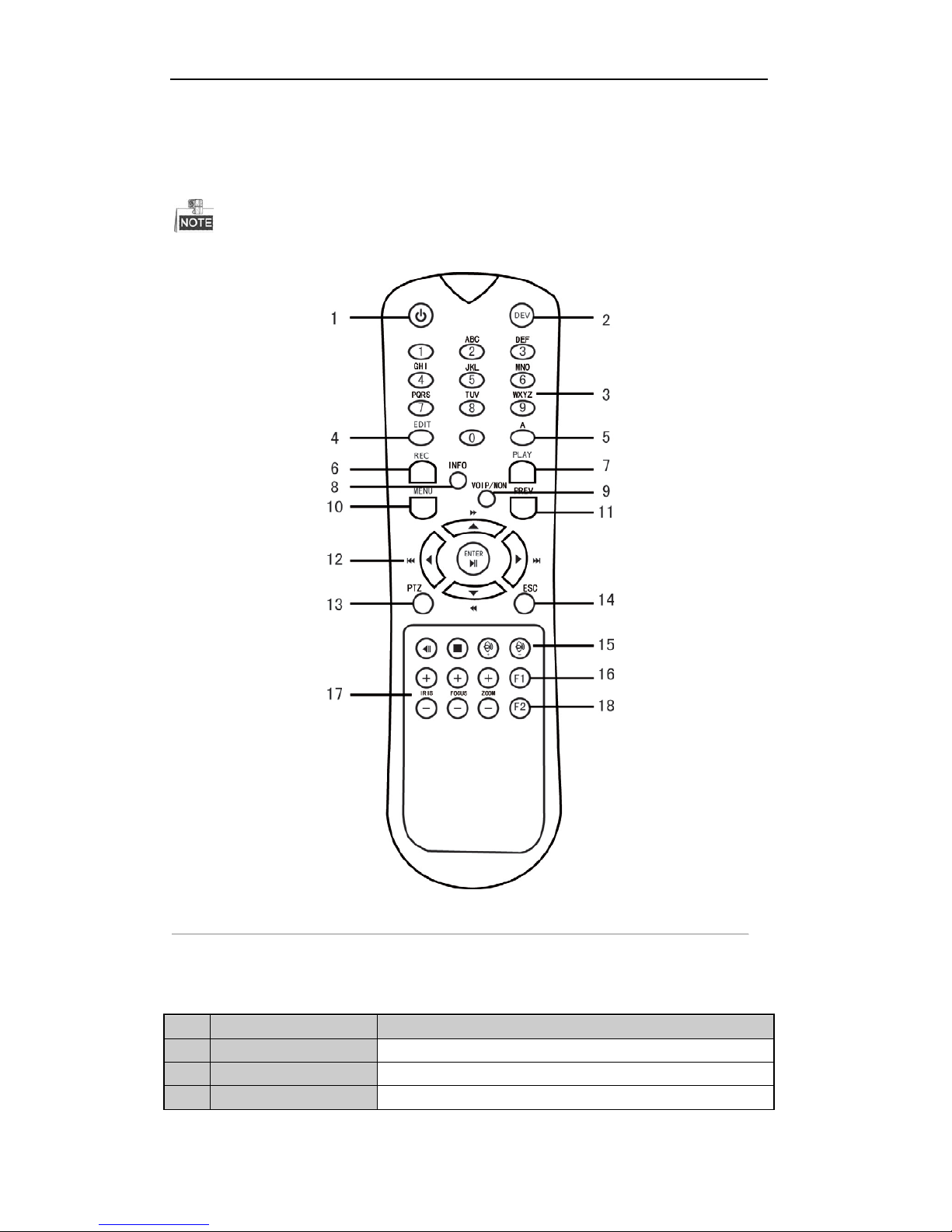
1.2 IR Remote Control Operations
The DVR may also be controlled with the included IR remote control, shown in Figure 1. 3.
Batteries (2×AAA) must be installed before operation.
Figure 1. 3 Remote Control
The keys on the remote control closely resemble the ones found on the front panel. Refer to Table 1. 3, they
include:
Table 1. 3 Description of the IR Remote Control Buttons
No. Name Description
1 POWER
Power on/off the device.
2 DEV
Enables/Disables Remote Control.
3 Alphanumeric Buttons
Same as Alphanumeric buttons on front panel.

User Manual of Digital Video Recorder
18
No. Name Description
4 EDIT Button
Same as EDIT/IRIS+ button on front panel.
5 A Button
Same as A/FOCUS+ button on front panel.
6 REC Button
Same as REC/SHOT button on front panel.
7 PLAY Button
Same as the PLAY/AUTO button on front panel.
8 INFO Button
Same as the ZOOM+ button on front panel.
9 VOIP/MON Button
Same as the MAIN/SPOT/ZOOM- button on front panel.
10 MENU Button
Same as the MENU/WIPER button on front panel.
11 PREV Button
Same as the PREV/FOCUS- button on front panel.
12 DIRECTION/ENTER
Buttons
Same as the DIRECTION/ENTER buttons on front panel.
13 PTZ Button
Same as the PTZ/IRIS- button on front panel.
14 ESC Button
Same as the ESC button on front panel.
15 RESERVED
Reserved for future usage.
16 F1 Button
Same as the F1/LIGHT button on front panel.
17 PTZ Control Buttons
Buttons to adjust the iris, focus and zoom of a PTZ camera.
18 F2 Button
Same as the F2/AUX button on front pane l .
Troubleshooting Remote Control:
Make sure you have instal l batteries properly in the remote control. And you have to aim the remote
control at the IR receiver in the front panel.
If there is no response after you press any button on the remote, follow the procedure below to troubleshoot.
Steps:
1. Go into Menu > Settings > General > More Settings by operating the front control panel or the mouse.
2. Check and remember DVR ID#. The default ID# is 255. This ID# is valid for all IR remote controls.
3. Press the DEV button on the remote control.
4. Enter the DVR ID# in step 2.
5. Press the ENTER button on the remote.
If the Status indicator on the front panel turns blue, the remote control is operating properly. If the Status
indicator does not turn blue and there is still no response from the remote, please check the following:
1. Batteries are installed correctly and the polarities of the batteries are not reversed.
2. Batteries are fresh and not out of charge.
3. IR receiver is not obstructed.
If the remote still cannot function properly, please change the remote and try again, or contact the device
provider.

User Manual of Digital Video Recorder
19
1.3 USB Mouse Operation
A regular 3-button (Left/Right/Scroll-wheel) USB mouse can also be used with this DVR. To use a USB mouse:
Steps:
1. Plug USB mouse into one of the USB interfaces on the front panel of the DVR.
2. The mouse should automatical ly be detected. If in a rare case that the mouse is not detected, the possible
reason may be that the two d evi ces are not compatible, please refer to the recommended the device list
from your provider.
The operation of the mouse:
Table 1. 4 Description of the Mouse Control
Name Action Description
Left-Click
Single-Click
Live view: Select channel and show the quick set menu.
Menu: Select and enter.
Double-Click
Live view: Switch between single-screen and multi-screen.
Click and Drag
PTZ control: Wheeling.
Privacy mask and motion detection: Select target area.
Digital zoom-in: Drag and select target area.
Live view: Drag channel/time bar.
Right-Click Single-Click
Live view: Show menu.
Menu: Exit current menu to upper level menu.
Scroll-Wheel Scrolling up
Live view: Previous scr een.
Menu: Previous item.
Scrolling down
Live view: Next screen.
Menu: Next item.
User Manual of Digital Video Recorder
20
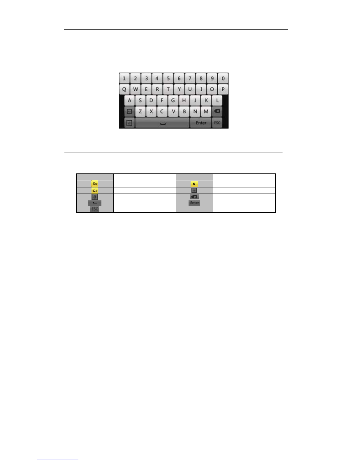
1.4 Input Method Descri p tion
Figure 1. 4 Soft Keyboard
Description of the b ut tons on the soft keyboard:
Table 1. 5 Description of the Soft Keyboard Icons
Icons Description Icons Description
English
Capital English
Numbers
Symbols
Lowercase/Uppercase
Backspace
Space
Enter
Exit
User Manual of Digital Video Recorder
21
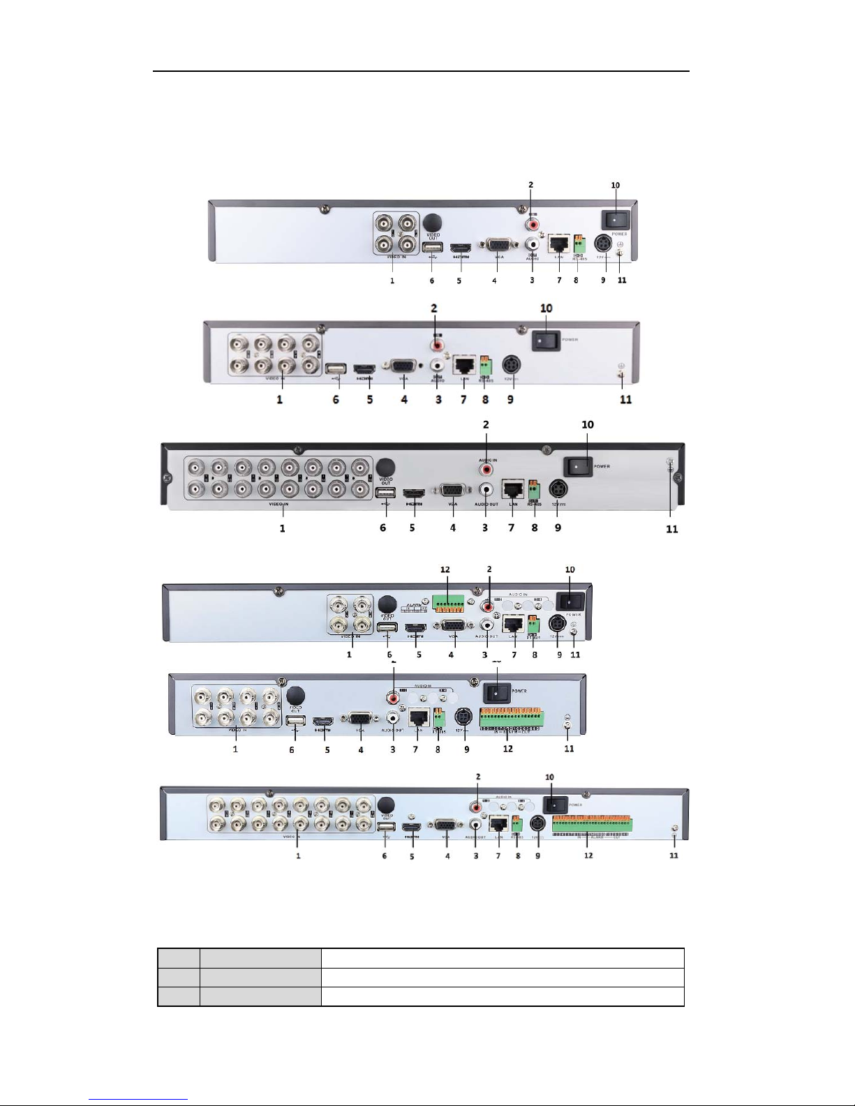
1.5 Rear Panel
Figure 1. 5 Rear Panel of 4/8/16ch 720p Series without alarm
Figure 1. 6 Rear Panel of 4/8/16ch 720p Series with alarm
Table 1. 6 Description of Front Panel
No. Item Description
1 VIDEO IN BNC interface for TVI and analog video input.
2 AUDIO IN RCA connector.
User Manual of Digital Video Recorder
22
3 AUDIO OUT RCA connector.
4 VGA DB15 connector for VGA output. Display local video output and menu.
5 HDMI HDMI video output connector.
6 USB Port Universal Serial Bus (USB) port for additional devices.
7 Network Interface Connector for network
8
RS-485 Interface Connector for RS-485 devices.
9 Powe r S upply DC 12V power supply.
10 Power Switch Switch for turning on/off the device.
11 GND Ground
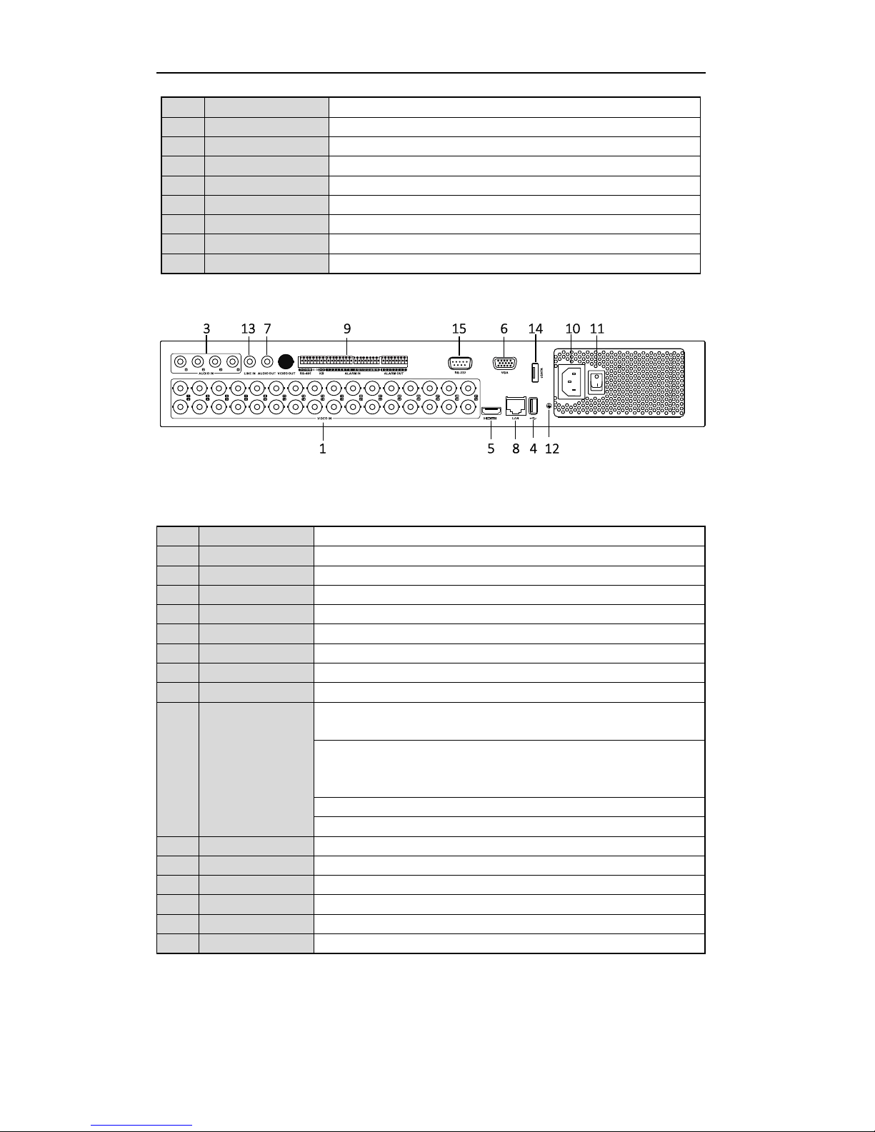
Figure 1. 7 Rear Panel of 32ch with alarm
Table 1. 7 Description of Rear Panel
No. Item Description
1 VIDEO IN BNC interface for TVI and analog video input.
2 VIDEO OUT BNC connector for video output.
3 AUDIO IN RCA connector
4 USB Port Universal Serial Bus (USB) port for additional devices.
5 HDMI HDMI video output connector.
6 VGA DB15 connector for V GA output. Display local video output and menu.
7 AUDIO OUT RCA connector
8 Network Interface Connector for network
9 RS-485 Interface Connector for RS-485 devices. T+ and T- pins connect to R+ and R- pins of
PTZ receiver respect ively.
D+, D- pin connects to Ta, Tb pin of controller. For cascading devices, the
first DVR’s D+, D- pin should be connected with the D+, D- pin of the next
DVR.
Connector for alarm input.
Connector for alarm output.
10 Power Supply AC 100 ~ 240V power supply.
11 Power Switch Switch for turning on/off the device.
12 GND Ground
13 LINE IN BNC connector for audio input.
14 eSATA Connects external SATA HDD, CD/DVD-RW.
15 RS-232 Interface Connector for RS-232 devices.

User Manual of Digital Video Recorder
23
Chapter 2 Getting Started
User Manual of Digital Video Recorder
24
2.1 Starting Up and Shutting Down the DVR
Purpose:
Proper startup and shutdown procedures are crucial to expanding the life of the DVR.
Before you start:
Check that the voltage of the extra power supply is the same with the DVR’s requirement, and the ground
connection is working properly.
Starting up the DVR
Steps:
1. Check the power supply is plugged into an electrical outlet. It is HIGHLY recommended that an
Uninterruptible Power Supply (UPS) be used in conjunction with the device.
2. Turn on the power switch on the rear panel, and the Power indicator LED should turn on indicatin g th at
the unit begins to start up.
3. After startup, the Power indicator LED remains on.
Shutting down the DVR
Steps:
There are two proper ways to shut down the DVR. To shut down the DVR:
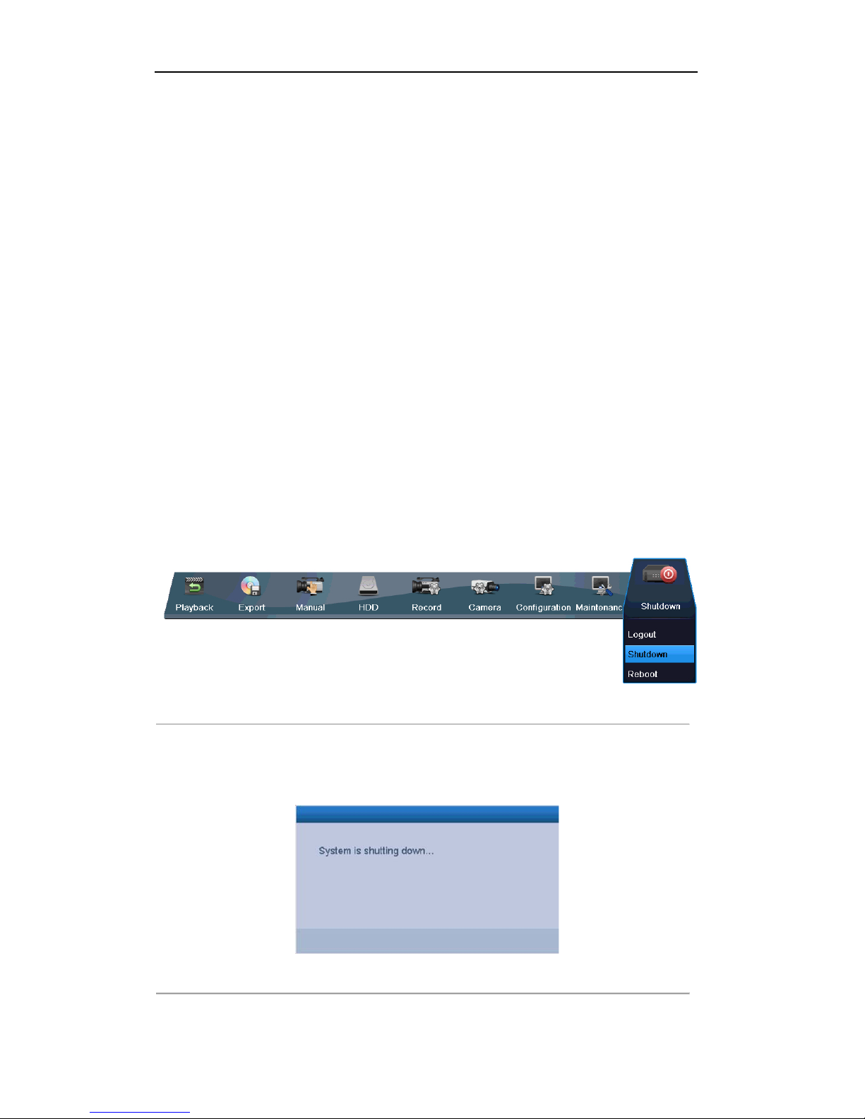
OPTION 1: Standard shutdown
1. Enter the Shutdown menu.
Menu > Shutdown
Figure 2. 1 Shutdown Menu
2. Select t he Shutdown button.
3. Click the Yes button.
4. Turn off the power switch on the rear panel when the note appears.
Figure 2. 2 Shutdown Tips

User Manual of Digital Video Recorder
25
Rebooting the DVR
While in the Shutdown menu (Figure 2. 1), you can also reboot the DVR.
Steps:
1. Enter the Shutdown menu by clicking Menu > Shutdown.
Click the Logout button to log out or the Reboot button to reboot the DVR.
User Manual of Digital Video Recorder
26
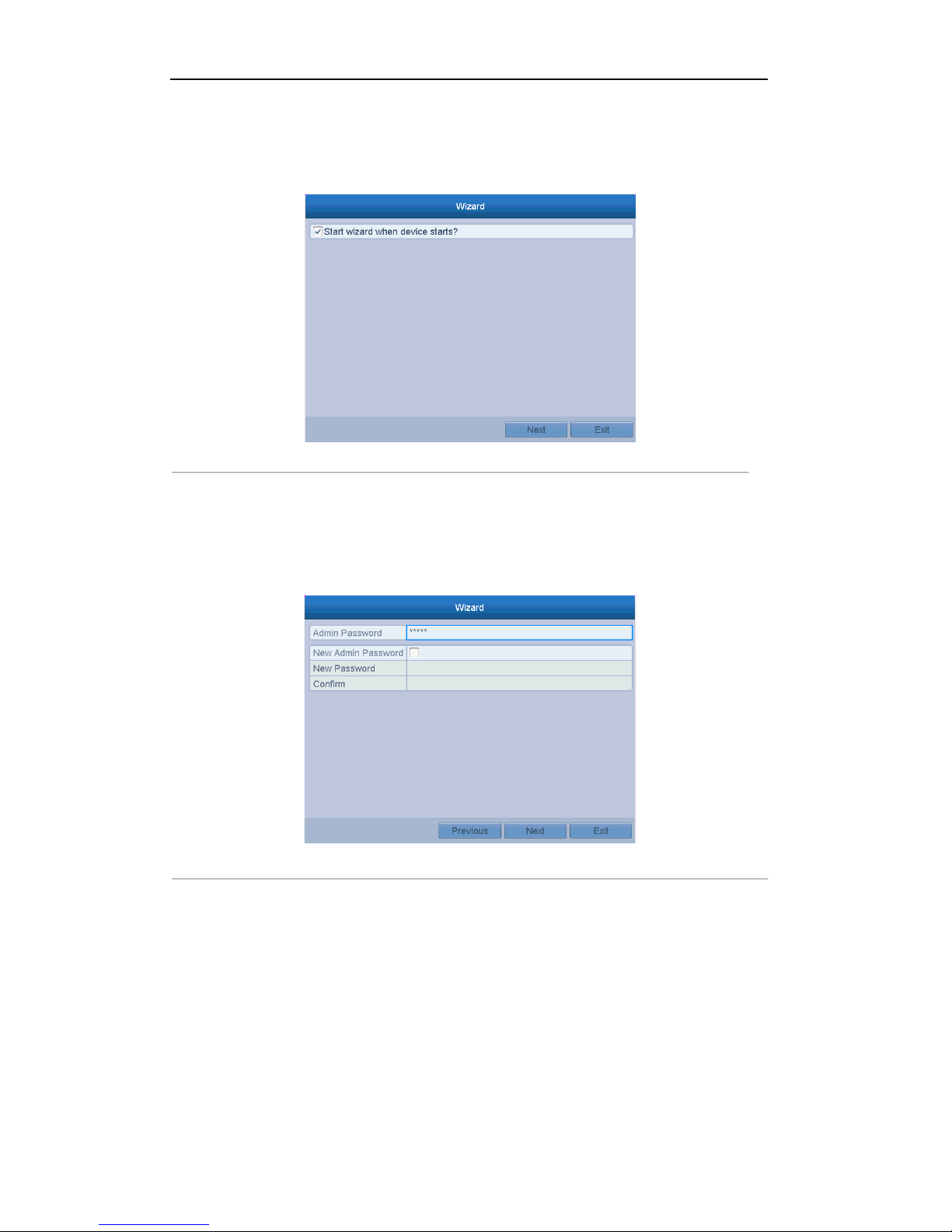
2.2 Using the Wizard for Basic Configuration
By default, the Setup Wizard starts once the device has loaded.
Figure 2. 3 Start Wizard Interface
Operating the Setup Wizar d:
1. The Start Wizard can walk you through some important settings of the device. If you don’t want to use the
Start Wizard at that moment, click Exit. You can also choose to use the Start Wizard next time by leaving
the “Start wizard when device starts?” checkbox checked.
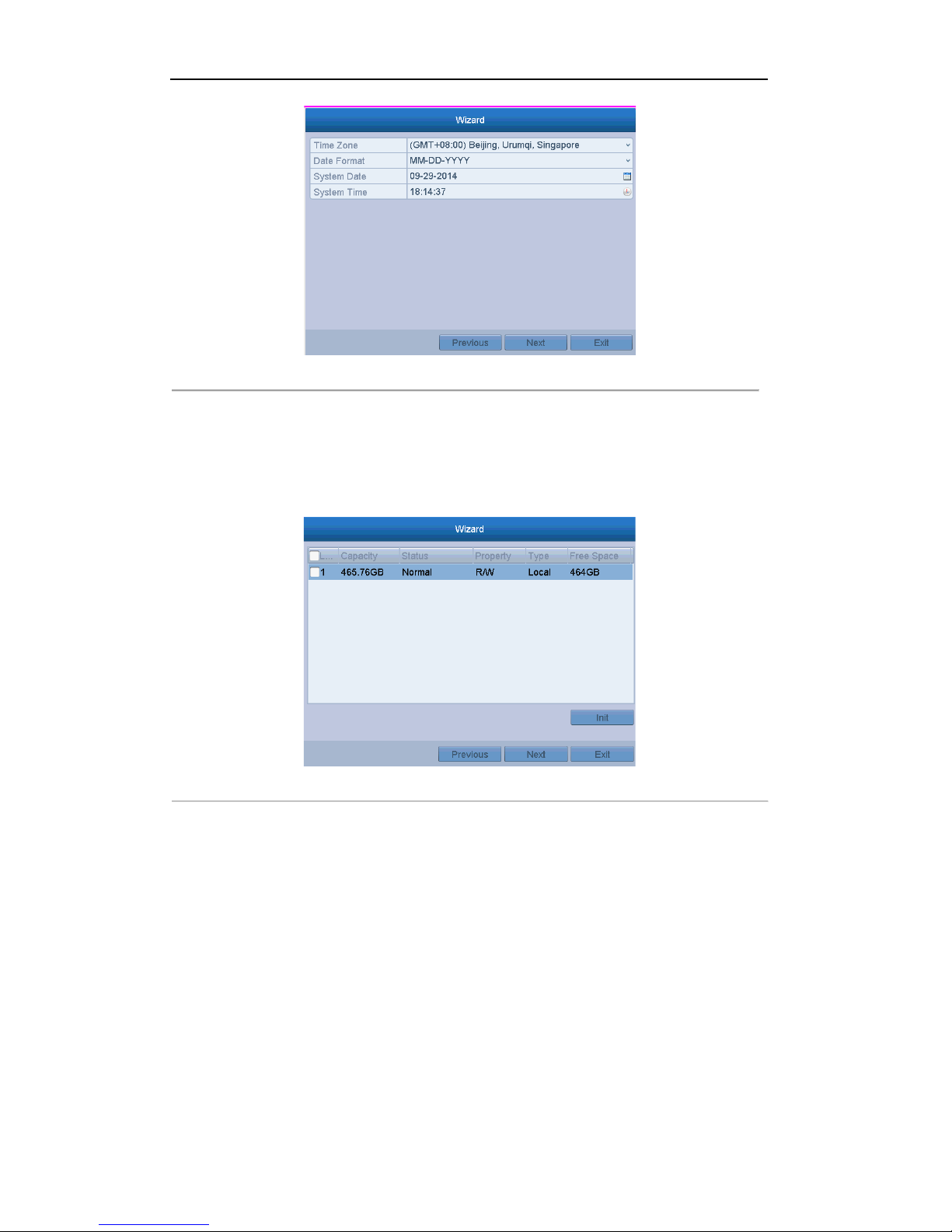
2. Click Next to enter the date and time settings window.
Figure 2. 4 Date and Time Settings
3. After the time settings, click Next button which will take you back to the General Network Setup Wizard
window, as shown in Fig ur e 2. 5.
User Manual of Digital Video Recorder
27
Figure 2. 5 General Network Configuration
4. Click Next button after you having configured the network parameters, which will take you to the
Advanced Network Setup Wizard window.
5. Set the parameters of port No., Cloud P2P, Auto UPnP or DDNS if required.
6. Click Next button after configuring the advanced network parameters, which will take you to the HDD
Management window, shown in Figure 2. 6.
Figure 2. 6 HDD Management
7. To initialize the HDD, click the Init button. Initialization will remove all the data saved in the HDD.
8. Click Next button to enter the Record Settings window, as shown in Figure 2. 7.

User Manual of Digital Video Recorder
28
Figure 2. 7 Record Settings
9. Click Copy to copy the recording setting to other cameras.
10. Click OK to save the settings and exit the wizard .
User Manual of Digital Video Recorder
29
2.3 Adding and Connecting the IP Cameras
Purpose:
Before you can get a live view or record of the video, you should add the network cameras to the connection list
of the device.
Before you start:
Ensure the network connection is valid and correct. For detailed checking and configuring of the network,
please see Chapter 9.
Note:For the 4-ch device, 1-ch IP camera can be connected; and for other models, up to 2-ch IP cameras can be
connected.
OPTION 1:
Steps:
1. Right-click the mouse when you in the live view mode to show the right-click menu.
Right-click Menu
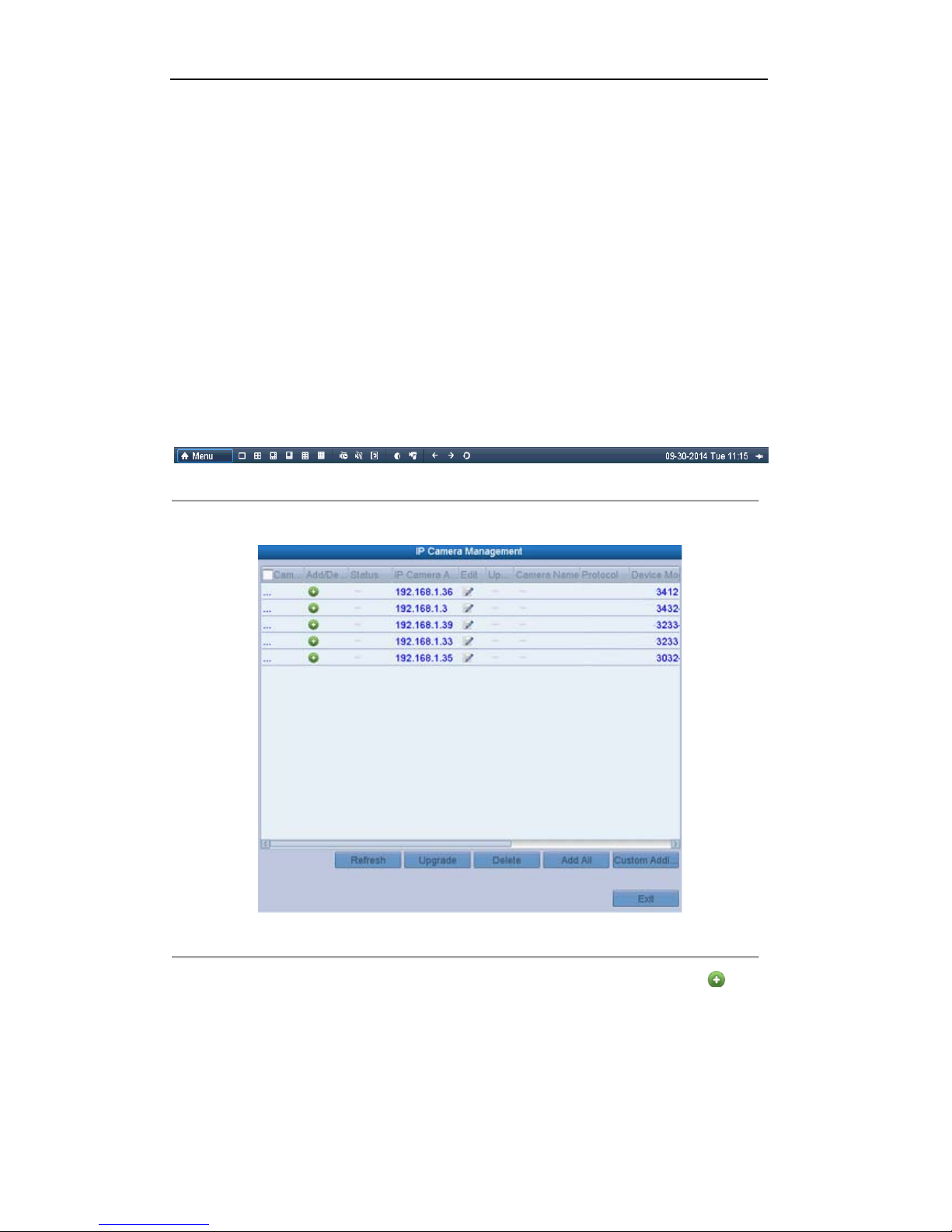
2. Select Add IP Camera in the pop-up menu to enter the IP Camera Management interface.
Figure 2. 8 Adding IP Camera Interface
3. The online cameras with s ame network segment will be displayed in the camera list. Click the button
to add the camera.Or you can click the Add All button to add all the detected online IP cameras.
User Manual of Digital Video Recorder
30
Table 2. 1 Explanation of the icons
Icon Explanation Icon Explanation
Edit basic parameters of th e camera
Add the detected IP camera.
The camera is connected.
The camera is disconn ected; you can click the
icon to get the exception information of camera.
Delete the IP camera
Advanced settings of the camera.
Update the IP camera
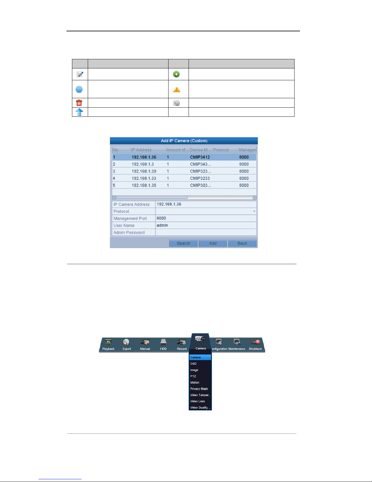
4. To add other IP cameras:
1) Click the Custom Adding button to pop up the Add IP Camera (Custom) interface.
Figure 2. 9 Custom Adding IP Camera Interface
2) You can edit the IP address, protocol, management port, and other information of the IP camera to be
added.
3) Click Add to add the camera.
OPTION 2:
Steps:
1. Enter the Camera Management interface.
Menu> Camera> Camera
Figure 2. 10 Main Menu
 Loading...