

Luxon Video TAVD2IR User Manual
HD-TVI
Turret & Dome Camera
User Manual
Tha nk you for p urcha sing ou r produc t. If the re
are a ny ques ons , or requ ests, pl ease do n ot
hes itate to c ontact t he deal er.
Thi s manua l may cont ain seve ral tec hnical
inc orrect p laces o r prin
g err ors, and t he
con tent is su bject t o chang e withou t ce.
The u pdates w ill be ad ded to th e new vers ion of
thi s manua l. We will r eadily i mprov e or updat e
the p roduc ts or proc edure s descr ibed in t he
man ual.
Reg ulato ry Info rma n
FCC I nforma n
FCC c ompli ance: T his equi pment h as been
test ed and fo und to com ply wit h the lim its for a
dig ital dev ice, pu rsuan t to part 1 5 of the FCC
Rul es. The se limi ts are des igned t o provi de
rea sonabl e prot
n agai nst har mful
int er
fere nce whe n the equ ipmen t is opera ted in
a com mercia l envir onment . This eq uipme nt
gen erates , uses, a nd can rad iate rad io
fre quenc y energy a nd, if no t insta lled an d used
in ac cordan ce with t he ins
n man ual, ma y
cau se harm ful inte rferen ce to radi o
com munic a
. Ope ra n of th is equi pment i n
a res iden
l are a is likel y to caus e harmfu l
int erferen ce in whi ch case t he user w ill be
req uired to c orrect t he inte rferen ce at his o wn
expe nse.
FCC
s
Thi s devic e compli es with p art 15 of t he FCC
Rul es. Ope ra
on is s ubjec t to the fol lowin g two
c
:
1. Th is devi ce may not c ause ha rmful
int erferen ce.
2. Th is devi ce must ac cept an y interf erence
rec eived,
inc ludin g interf erence t hat may
cau se unde sired op era
n.
EU Co nform it y Sta temen t
upo n th e pu rc has e of e qu iva le nt n ew e qui pm en t,
or di sp os e of i t at de si gn at ed c oll ec ti on po in ts .
For m or e in for ma ti on s ee:
www. recycl ethis .info.
200 6/66/ EC (ba
ery d ire ve): This
pro duct con tains a b a
ery t hat cann ot
be di spose d of as uns orted m unici pal
wast e in the Eu ropea n Union .
See t he produ ct docu menta
n for sp ecifi c
ba
ery i nforma
on. T he ba
ery i s marked w ith
thi s symbo l, which m ay incl ude le
eri ng to
ind icate ca dmium ( Cd), le ad (Pb) , or mercu ry (Hg ).
For p roper re cyclin g, retu rn the ba
ery t o your
sup plier o r to a desi gnated c
n poi nt. For
mor e inform a
on se e: www.re cyclet his.i nfo.
Thi s serie s of came ra adopt s new gen era
on
sen sor wit h high se nsi
vit y and adv anced c ircuit
des ign tec hnolo gy It fe atures h igh re
,.
lo
w ima ge disto r
on an d low noi se, etc , whi ch.
make s it suit able for s urvei llanc e system a nd
ima ge proce ssing s ystem.
Hig h perfor mance C MOS sen sor and h igh
re
n bri ng high -qual ity ima ge;
Low i llumi na
;
OSD m enu, pa ramete rs are con figurab le;
Sup port au to whit e balanc e, auto g ain cont rol,
ele ctron ic shu
er co ntrol;
SMA RT IR mod e;
Uni t transm issio n contr ol;
Adv anced 3 -axis de sign me ets diff ere nt
ins talla
on re quirem ents.
1 Intr
n
1.1 Pro duct Feat ures
1.2 Ove rv ie w
201 2/19/ EU (WEE E dire ve) :
Pro ducts m arked wi th this sy mbol
can not be di spose d of as uns orted
mun ic ip al w ast e in t he E ur ope an
Uni on . Fo r pro pe r re cyc li ng , re tur n
thi s pr od uc t to yo ur l oc al s upp li er
Ple ase refe r to the pro duct sp ecific a n for
cam era para meters a nd
.
Thi s produ ct and - if a pplica ble - the
sup plied a ccess ories t oo are mar ked
wit h "CE" an d compl y theref ore with
the a pplic able ha rmoni zed Euro pean
stan dards l isted u nder th e Low Volta ge Dire
ve
200 6/95/ EC, the EMC Dir e
ve 20 04/10 8/EC ,
the Ro HS Dire
ve 20 11/65 /EU.
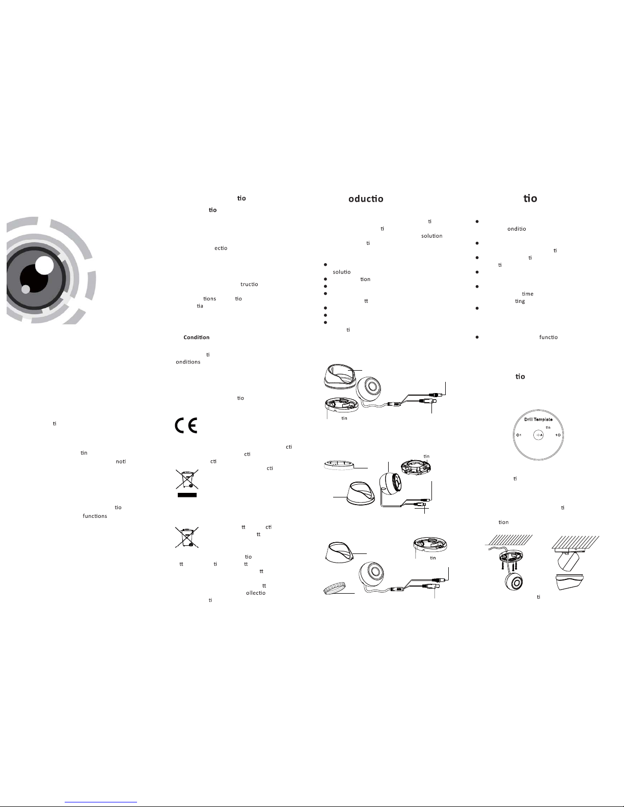
1.2 .1 Over view of Ty pe I Came ra
HD Vi deo Cab le
Mou n
g Bas e
Cam era
Enc losure
1.2 .2 Over view of Ty pe Came ra
II
Enc losure
HD Vid eo Cabl e
Powe r Cable
Moun
g Base
1.2 .3 Over view of Ty pe Cam eraIII
Powe r Cable
HD Vid eo Cabl e
Powe r Cable
2 Installa n
Bef ore y ou st art :
Ple ase make s ure tha t the devi ce in the p ackag e
is in g ood c
n and a ll the as sembl y parts
are i nclud ed.
Make s ure tha t all the re lated e quipm ent is
pow er-off d uring t he inst alla
on.
Che ck the sp ecific a
on of t he prod ucts for t he
ins talla
on en vironm ent.
Che ck whet her the p ower sup ply is ma tched
wit h your po wer outp ut to avo id damag e.
Ple ase make s ure the wa ll is str ong eno ugh to
wit hstand t hree
s the w eight o f the came ra
and t he moun
.
If th e wall is t he ceme nt wall, y ou need to i nsert
exp ansio n screws b efore yo u instal l the cam era.
If th e wall is t he woode n wall, y ou can us e
sel f-tap ping sc rew to sec ure the ca mera.
If th e produ ct does n ot n pro perly,
ple ase con tact you r deale r or the ne arest
ser vice ce nter. Do not d isass emble t he came ra
for re pair or m ainte nance b y yourse lf.
2.1 Ins talla n of Type CameraI
Ste ps:
1.Dr ill the s crew hol es and th e cable h ole
acc ording t o the dri ll temp late.
Fig ure 2-1 T he Drill Te mplate
2.Fi x the mou n ng bas e to the ce iling w ith the
sup plied s crews.
3.Rou te the ca bles to t he cabl e hole and c onnec t
the c orresp ondin g power c able an d video c able.
4.Se cure th e camera t o the mou n
ng ba se.
5.Fi x the enc losur e to camer a to compl et the
ins talla
.
Hole A : for cabl es route d
throu gh the wa ll.
Hole 1 : for moun
g base
Fig ure 2-2 Fi x the Mou n ng Ba se and th e Camera
Trim Ri ng
Enc losure
Moun
g Base
Trim Ring
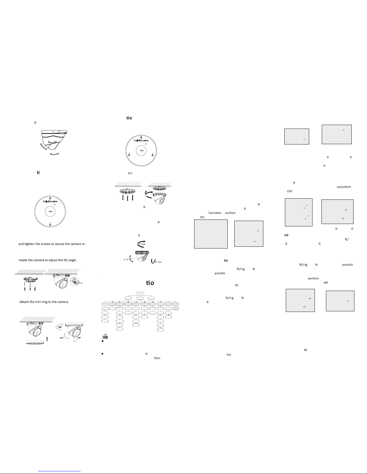
Fig ure 2-3 3 -axis Ad justm ent
0 ~36 0° °
0 ~75° °
0 ~360° °
2.2 Ins talla n of Ty pe CameraII
Ste ps:
Fig ure 2-4 T he Dril l Temp late
Fig ure 2-5 F ix the camera to the ceiling
Fig ure 2-6
2.3 Ins talla n of Type CameraIII
Ste ps:
3 Menu Opera n
Fig ure 3-1 M ain Men u
Menu
SCENE
LENS
RESET
EXPOSURE
WB
DAY&NIGHT
BACKLIGHT
NR
SPECIAL
ADJUST
INDOOR
OUTDOOR
INDOOR1
LOWLIGHT
MANUAL
SHUTTER
AGC
SENS-UP
BRIGHTNESS
D-WDR
DEFOG
BLC
HSBLC
ATW
AWC-SET
INDOOR
OUTDOOR
MANUAL
COLOR
B/W
EXT
2DN R
3DN R
CAM
TITLE
D-EFFECT
MOTION
PRIVACY
LAUGUAGE
DEFECT
VERSION
SHARPNESS
MONITOR
LSC
VIDEO.
OUT
EXIT
SETUP
A coa xial cam era cont rolle r (purc hase se parate ly)
is re quired t o selec t the men u and adj ust the
cam era para meters .
3.1 V IDEO.O UT
PAL or NT SC is sel ectab le .
3.2 L ANGUAG E
Eng lish, J apane se, CHN 1, CHN2 , Korean , Germa n,
Fre nch, Ita lian, S panis h, Poli sh, etc. , are sel ectab le.
3.3 SETUP
3.3 .1 SCEN E
You can s elect i ndoor, ou tdoor, in door 1 an d low
-li ght as th e workin g enviro nment s.
3.3 .2 LENS
The c amera is e quipp ed with a fi xed l ens.
3.3 .3 EXPO SURE
EXPOSURE
1. SHUTTER AUTO
2. AGC OFF
3. SENS-UP ---
4. BRIGHTNESS ---|------4 0
5. DEFOG OFF
6. BACKLIGHT OFF
7. RETURN RET
Fig ure 3-2 E xposu re
SHU TTER: A UTO,1/ 25, 1/5 0, FLK, 1 /200, 1/ 400,
1/1 k, 1/2k , 1/5k, 1 /10k, 1 /50k, x 2, x4, x6, x 8, x10,
and x 15 are se lectab le.
: You can s et the AG C value fr om 0 to 15.AGC
: You can s et the SE NS-UP t o OFF or AUT O.SEN S-UP
: You can s et the br ightn ess valu eBRI GHTNE SS
fro m 1 to 100.
: You can s et the D- WDR to ON to i mprov eD-W DR
the i mage qu ality o r OFF to dis able th e f
unc on .
: You can s et the de fog func
on as O N toDEF OG
ena ble the
. P , size , and the d efog
grad a
n are co nfigur able.
3.3 .4 Back light
Bac kligh t Compen s
a
n (BL C):
Set t he gain of B LC as Hig h, Midd le, or Lo w.-GA IN:
Pre ss the up/ down/ le
ht bu o n to-AREA :
defi ne th e BLC
n and s ize. Sel ect RET o r
AGA IN to go bac k the BLC m enu or re -define t he
BLC a rea.
Rest ore the B LC se
ngs t o the defa ult.-De fault:
HSB LC:
Sel ect an HS BLC area . Set the D ISPLAY st atus as O N.
Pre ss the up/ down/ le
ht bu o n to defin e the
are a posi
on an d size. Se t the HSB LC LEVE L from 0
to 10 0. Sele ct ALL DAY or N ight for t he HSBL C mode.
Set t he BLAC K MASK sta tus as ON o r OFF.
HSBLC
1. SELECT AREA 1
2. DISPLAY ON
3. LEVEL ---|------ 40
4. MODE ALL DAY
5. BLACK MASK ON
6. DEFAULT
7. RETURN RET
Fig ure 3-3 H SBLC
3.3 .5 White B alanc e (WB)
IND OOR, OU TDOOR , MANUAL , ATW (Aut o-trac king
Whi te Bala nce), AWC →SET ar e selec table .
3.3 .6 Day & Nig ht
Col or, B/W, and EX T are sele ctabl e for DAY and
NIG HT switc hes.
3.3 .7 NR
: You can s et 2D NR sta tus as ON o r OFF.2D NR
: Set t he Smar t NR statu s as ON and a djust3D NR
the 3 D smart N R sensi
ty ran ges fro m 0 to 100.
Set t he 3D NR LE VEL rang es from 0 to 1 00. Set t he
2D&3 D NR
1. 2D NR OFF
2. 3D NR ON
3. RE TURN RE T
3D NR
1. SMART NR ON
2. LEVEL ------|--8 0
3. START. AGC -|--------10
4. END. AGC -|--------10
5. RETURN RET
Fig ure 3-5 NR
Fig ure 3-6 3 D NR
3.3 .8 SPEC IAL
: Edi t the came ra
tle o n this se c o n.Camer a Title
:D-e ffect
: Set t he freez e func
on as O N or OFF.-FR EEZE
: OFF, MI RROR, V- FLIP, and RO TATE are-MIR ROR
sel ectabl e for mir ror.
: Defi ne th e zoom are a by config uring-D- ZOOM
the p osi
on fr om PAN & TILT.
: The D -Zoom a rea,
y-SM ART D-Z OOM
and
e are co nfigur able.
: Set t he NEG IMA GE as ON or O FF.- NEG.I MAGE
SPECIAL
1. CAM TITLE ON
2. D-DFFECT
3. MOTION OFF
4. PRIVACY OFF
5. LANGUAGE ENG
6. DEFECT
7. VERSION 130722
8. RETURN RET
Fig ure 3-7 S pecia l
MOTION
1. SELECT AREA 1
2. DISPLAY ON
3. SENSITIVITY ----|---- 30
4. MOTION VIEW ON
5. DEFAULT
6. RETURN RET
Fig ure 3-8 M o o n Detec on
M
on : Selec t a MOTION a rea. Se t the DIS PLAY
stat us as ON or O FF. Press t he up/d own/l e
rig ht
bu
on to d efine the p osi o n and siz e of the are a.
Set t he SENS ITIVI TY from 0 to 6 0. Set th e MOTION
VIE W status a s ON or OFF.
Pri vacy: S elect a P RIVACY ar ea. Set t he DISP LAY
stat us as INV, MO SAIC, C OLOR or OF F. Pre ss the
up/ down/ le
ht bu o n to defin e the n
and s ize of the a rea.
Defe ct: LIV E DPC, STATI C DPC and B lack DP C are
adj ustabl e in this
.
: You can c heck th e s
ware v ersio n of theVersio n
dev ice.
PRIVACY
1. SELECT AREA 1
2. DISPLAY MOSAIC
3. COLOR 10
4. TRANS. 1
5. DEFAULT
6. RETURN RET
ADJUST
1. SHARPNESS
--------|15
2. MONITOR LCD
3. LSC OFF
4. VIDEO. OUT PAL
5. RETURN RET
3.3 .9 ADJU ST
: Adj ust the s harpn ess from 0 t o 15.Sharpn ess
: Mon itor CR T, and M onitor L CD areMon itor
sel ectabl e.
: Set t he LSC sta tus as ON o r OFF.LSC
3.3 .10 RES ET
Res et all the s e
ngs t o the defa ult.
3.3 .11 EXI T
Pre ss OK to exi t the men u.
START. AGC l evel as t he thre shold to e nable A GC,
and s et the EN D. AGC lev el as the t hresho ld to
dis able AG C.
Fig ure 3-9 P rivacy M ask
Fig ure 3-1 0 Adjust
Hole 1 : for moun ng b ase
Hole A : for cabl es route d
throu gh the wa ll.
Cam eras wit h a 720p re solu on of t hese th ree
typ es do not s uppor t menu op era .
1.Dr ill the s crew hol es and th e cable h ole on th e
cei ling ac cordin g to the su pplie d drill t emplat e.
Fig ure 2-6 T he Dril l Temp late
2.Fi x the mou n g base t o the cei ling wi th the
sup plied s crews.
Hole 1 : for moun ng b ase
Hole A : for cabl es route d
throu gh the wa ll.
Fig ure 2-7 F ix the Mou n ng Ba se and Ca mera
3.Rou te the ca bles to t he cabl e hole and c onnec t
cor respon ding po wer cab le and vi deo cab le.
4.Se cure th e camera t o the mou n
ng ba se.
5.Fi x the enc losur e to camer a.
6.A djust t he came ra accor ding to th e figure
bel ow to get an o p
mum a ngle.
Fig ure 2-8 3 -axis Ad justm ent
6.Ad just th e camera a ccordi ng to the fi gur e below
to get a n op
mum a ngle .
1.Drill the screw holes and the cable hole on the
ceiling according to the drill template.
2.Connect the corresponding power/video cables.
3.Insert the supplied screws to the screw holes
the ceiling.
4.Loosen the lock screw.
5.Rotate the enclosure to adjust the pan angle;
6.Tighten the lock screw to clamp the lens.
o
7.
8.Rotate the trim ring clockwise to secure it to
the camera.
Install the trim ring
 Loading...